

page 314
52. COMPOSITE MANUFACTURING
•Each material has desirable properties, but in most situations the perfect material is never found.
•Composites allow mixing of materials to get the best of both.
•BASIC PRINCIPLE: different types of materials are blended together. The materials are often quite different in terms of properties, and the results are a new material that has many of the desired properties of each material.
•Examples
-clay bricks with embedded straw
-reinforced concrete
-samurai swords with steel/iron alternation of layers
-steel belted radials
-graphite tennis racquets
-fishing poles
•for reinforced plastic composites, 2,500,000,000 pounds of plastic based composites were shipped in a wide variety of products in the mid 80’s
52.1 FIBER REINFORCED PLASTICS (FRP)
•Typical properties that may be desired are,
-light weight
-stiffness
-strength
-heat resistant
-impact resistance
-electrical conductivity
-wear resistance
-corrosion resistance
-low cost
•Some notable applications are,
-Automotive - engine blocks, push rods, frames, piston rods, etc.
-Electrical - motor brushes, cable electrical contacts, etc
-Medical - prostheses, wheel chairs, orthofies, etc.
-Sports equipment - tennis racquets, ski poles, skis, fishing rods, golf clubs, bicycle frames, motorcycle frames
-Textile industry - shuttles
-etc.
page 315
•Some advantages are,
-composites provide a maximum tensile strength to density ration approximately 4 to 6 times greater than steel or aluminum
-can provide a maximum material stiffness to density ratio of 3.5 to 5 times that of aluminum or steel
-high fatigue endurance limits
-absorb higher impact energies
-material properties can be strengthened where required
-corrosion potential is reduced.
-joints and fasteners are eliminated or simplified
•Some disadvantages are,
-If either material is susceptible to local solvents, the composite cannot be used
-materials can be expensive
-design and fabrication techniques are not well explored and developed.
•fibres are often graphite, glass, aramid, etc.
•the fibres are supported in the matrix, quite often a polymer, epoxy, etc.
•The polymer matrix is often referred to as the resin
•The matrix transfers the load to the reinforcement fibres, and it protects the fibres from environmental effects.
•Resins tend to be thermosetting, or thermoplastic
Thermoplastics - melt, and harden with temperature
Thermosets - undergo a chemical change, and cannot be “recast”. The setting is often heat activated.
• Polyester resins are quite common. The process often begins with molecules like a dialcohol, and diacid. These then cure into a solid polymer.
page 316
|
|
|
|
O |
|
O |
|
|
|
|
|
|
|||||||||
H |
|
O |
|
C |
|
|
CH |
|
CH |
|
C |
|
|
O |
|
H |
|||||
|
|
|
|
|
|
|
|
|
|||||||||||||
|
|
|
|
|
|
|
|
|
|||||||||||||
|
|
|
|
|
|
|
|||||||||||||||
Maleic Acid (A diacid) |
|
|
|
|
|
|
|
|
|
|
|
|
|||||||||
|
|
|
|
|
|
|
|
|
|
|
|
|
|
HO |
|
CH2 |
|
CH2 |
|
OH |
|
|
|
|
|
|
|
|
|
|
|
|
|
|
|
|
|
|
|||||
|
|
|
|
|
|
|
|
|
|
|
|
|
|
|
|
|
|
|
Ethylene Glycol |
||
|
|
|
|
|
|
|
|
|
|
|
|
|
|
|
|
|
|
|
(A dialcohol) |
||
|
|
|
|
|
|
|
an ester |
|
|
|||||||||||||
|
|
|
|
|
|
|
|
|
|
|
|
|
ester linkage |
|
|
|||||||
|
|
|
|
O |
|
|
|
|
|
O |
|
|
||||||||||
|
|
|
|
|
|
|
|
|
|
|
|
|
|
|
|
|
|
|
|
|
+ |
|
|
|
|
|
|
|
|
|
|
|
|
|
|
|
|
|
|
|
|
|
|
|
|
H |
|
O |
|
C |
|
CH |
|
CH |
|
C |
|
O |
|
CH2 |
|
CH2 |
|
OH |
H2O |
|||
|
|
|
|
|
|
|
|
|
|
|||||||||||||
|
|
|
|
|
|
|
|
|
|
|
|
|
|
|
|
|
|
|
|
|
|
water is a |
|
|
|
|
|
|
|
|
|
|
|
|
|
|
|
|
|
|
|
|
|
|
byproduct |
|
|
|
|
|
|
|
these ends now link in similar ways |
|
|
|||||||||||||
• These reactions create very long chains of polymers in a sort of gel, but the next step involves cross-linking them to make things stiff
page 317
polyester |
|
|
|
|
|
|
|
|
|
|
|
|
|
|
|||||||||
|
|
O |
|
|
O |
|
|
||||||||||||||||
|
|
|
|
|
|
|
|
|
|
|
|
|
|
|
|
|
|
|
|
|
|
|
|
|
|
|
|
|
|
|
|
|
|
|
|
|
|
|
|
|
|
|
|
|
|
|
|
|
|
C |
|
CH |
|
|
CH |
|
C |
|
|
O |
|
CH2 |
|
CH2 |
|
O |
|
n |
|||
|
|
|
|
|
|
|
|
|
|
|
|
||||||||||||
|
|
|
|
|
|
|
|
|
|
|
|
|
|
|
|
|
|
|
|
|
|
|
|
peroxide initiator |
|
|
|
|
|
|
|
|
|
|
|
|
|
|
|||||||||
Reactants |
|
|
|
|
|
|
|
|
|
|
|
|
|
|
|||||||||
|
RO |
|
|
|
|
|
|
|
|
|
|
|
|
|
|
||||||||
Cross linking Agent |
|
|
|
|
|
|
|
|
|
|
|
|
|
|
|||||||||
(styrene) |
|
|
|
|
|
|
|
|
|
|
|
|
|
|
|||||||||
|
|
|
|
|
|
|
|
|
|
|
|
|
|
|
|
|
|
|
|
|
|
|
|
CH |
|
|
|
|
CH2 |
|
|
|
|
|
|
|
|
|
|
|
|
|
|
|
|
|
|
|
|
|||||||||||||||||||
|
|
|
|
|
|
|
|
|
|
|
|
|
|
|
|
|
|
|
|
|
|
|
|
|
|
|
|
|
|
|
|
|
|
|
|
|
|
|
|
|
|
|
|
|
|
|
|
|||||||||||||||||||||
|
|
|
|
|
|
|
|
|
|
|
O |
|
|
|
|
|
|
|
|
|
|
|
|
|
|
|
|
|
|
|
|
|
|
|
|
O |
|
|
|
|
|
|
|
|
|
|
|
|
|
|
|
|
|
|
|
|
||||||||||||
Initiation step |
|
|
|
|
|
|
|
|
|
|
|
|
|
|
|
|
|
|
|
|
|
|
|
|
|
|
|
|
|
|
|
|
|
|
|
|
|
|
|
|
|
|
|
|
|
|
|
|
|
|
|
|
|
|
|
|
|
|
|
|
|
|
|
|
|
|
|
|
|
|
|
|
|
|
|
|
|
|
|
|
|
|
|
|
|
|
|
|
|
|
|
|
|
|
|
|
|
|
|
|
|
|
|
|
|
|
|
|
|
|
|
|
|
|
|
|
|
|
|
|
|
|
|
|
|
|
|
|
|
|
|
|
|
|
|
|
|
|
|
|
|
|
|
|
|
|
|
|
|
|
|
|
|
|
|
|
|
|
|
|
|
|
|
|
|
|
|
|
|
|
|
|
|
|
|
|
|
|
|
|
|
|
|
|
|
|
|
|
|
|
|
|
|
|
|
|
|
|
|
|
|
|
|
|
|
|
|
|
|
|
|
|
|
|
|
|
C |
|
|
|
CH |
|
|
|
CH |
|
|
|
|
|
C |
|
|
|
O |
|
CH2 |
|
|
|
CH2 O |
|
|
n |
|
|
|||||||||||||||||||||||||||||
|
|
|
|
|
|
|
|
|
|
|
|
|
|
|
|
|
|
|
|
|
|
|
|
|
|
|
|
|
|
|
|
|
||||||||||||||||||||||||||||||||||||
|
|
|
|
|
|
|
|
|
|
|
|
|
|
|
|
|
|
|
|
|
|
|
|
|
|
|
|
|
|
|
|
|
|
|
|
|
|
|
|
|
|
|
|
|
|
|
|
|
|
|
|
|
|
|
|
|
|
|
|
|
|
|
|
|
|
|
|
|
|
|
|
|
|
|
|
|
|
|
|
|
|
|
|
|
|
|
|
|
|
|
|
|
|
|
|
|
|
|
|
O |
|
R |
|
|
|
|
|
|
|
|
|
|
|
|
|
|
|
|
|
|
|
|
|||||||||||||||
|
|
|
|
|
|
|
|
|
|
|
|
|
|
|
|
|
|
|
|
|
|
|
|
|
|
|
|
|
|
|
|
|
|
|
|
|
|
|
|
|
|
|
|
|
|
|
|
|
|
|
|
|||||||||||||||||
|
|
|
|
|
|
|
|
|
|
|
|
|
|
|
|
O |
|
|
|
|
|
|
|
|
|
|
|
|
|
|
|
|
|
|
|
O |
|
|
|
|
|
|
|
|
|
|
|
|
|
|
|
|
|
|
|
|
||||||||||||
|
|
|
|
|
|
|
|
|
|
|
|
|
|
|
|
|
|
|
|
|
|
|
|
|
|
|
|
|
|
|
|
|
|
|
|
|
|
|
|
|
|
|
|
|
|
|
|
|
|
|
|
|
|
|
|
|
|
|||||||||||
|
|
|
|
|
|
|
|
|
|
|
|
|
|
|
|
|
|
|
|
|
|
|
|
|
|
|
|
|
|
|
|
|
|
|
|
|
|
|
|
|
|
|
|
|
|
|
|
|
|
|
|
|
|
|
|
|
|
|
|
|||||||||
Bridging Step |
|
|
|
|
|
|
|
|
|
|
|
|
|
|
|
|
C |
|
|
|
|
CH |
|
|
|
|
CH |
|
|
|
C |
|
|
|
|
|
O |
|
CH2 |
|
|
CH2 |
|
|
|
O |
|
n |
||||||||||||||||||||
|
|
|
|
|
|
|
|
|
|
|
|
|
|
|
|
|
|
|
|
|
|
|
|
|
|
|
|
|
|
|
|
|
|
|
||||||||||||||||||||||||||||||||||
|
|
|
|
|
|
|
|
|
|
|
|
|
|
|
|
|
|
|
|
|
|
|
|
|
|
|
|
|
|
|
|
|
|
|
|
|
OR |
|
|
|
|
|
|
|
|
|
|
|
|
|
|
|
|
|
|
|
||||||||||||
|
|
|
|
|
|
|
|
|
|
|
|
|
|
|
|
|
|
|
|
|
|
|
|
|
|
|
|
|
|
|
|
|
|
|
|
|
|
|
|
|
|
|
|
|
|
|
|
|
|
|
|
|
|
|
|
|
||||||||||||
|
|
|
|
|
|
|
|
|
|
|
|
|
|
|
|
|
|
|
|
|
|
|
|
|
|
|
|
|
|
|
|
|
|
|
|
|
|
|
|
|
|
|
|
|
|
|
|
|
|
|
|
|
|
|
|
|
|
|||||||||||
|
|
|
|
|
|
|
|
|
|
|
|
|
CH |
|
|
|
|
|
CH2 |
|
|
|
|
|
|
|
|
|
|
|
|
|
|
|
|
|
|
|
|
|
|
|
|
|
|
|
|
|
|
|
|
|
|
|
|
|||||||||||||
|
|
|
|
|
|
|
|
|
|
|
|
|
|
|
|
|
|
|
|
|
|
|
|
|
|
|
|
|
|
|
|
|
|
|
|
|
|
|
|
|
|
|
|
|
|
|
|
|
|
|
|
|
||||||||||||||||
|
|
|
|
|
|
|
|
|
|
|
|
|
|
|
|
O |
|
|
|
|
|
|
|
|
|
|
|
|
|
|
|
|
|
|
|
O |
|
|
|
|
|
|
|
|
|
|
|
|
|
|
|
|
|
|
|
|
||||||||||||
|
|
|
|
|
|
|
|
|
|
|
|
|
|
|
|
|
|
|
|
|
|
|
|
|
|
|
|
|
|
|
|
|
|
|
|
|
|
|
|
|
|
|
|
|
|
|
|
|
|
|
|
|
|
|
||||||||||||||
|
|
|
|
|
|
|
|
|
|
|
|
|
|
|
|
|
|
|
|
|
|
|
|
|
|
|
|
|
|
|
|
|
|
|
|
|
|
|
|
|
|
|
|
|
|
|
|
|
|
|
|
|
|
|
||||||||||||||
|
|
|
|
|
|
|
|
|
|
|
|
|
|
|
|
|
|
|
|
|
|
|
|
|
|
|
|
|
|
|
|
|
|
|
|
|
|
|
|
|
|
|
|
|
|
|
|
|
|
|
|
|
|
|
|
|
|
|
|
|||||||||
Crosslinked |
|
|
|
|
|
|
|
|
|
|
|
|
|
|
|
|
C |
|
|
|
|
CH |
|
|
|
|
CH |
|
|
|
C |
|
|
|
|
|
O |
|
CH2 |
|
|
CH2 |
|
|
|
O |
|
n |
||||||||||||||||||||
|
|
|
|
|
|
|
|
|
|
|
|
|
|
|
|
|
|
|
|
|
|
|
|
|
|
|
|
|
|
|
|
|
|
|||||||||||||||||||||||||||||||||||
|
|
|
|
|
|
|
|
|
|
|
|
|
|
|
|
|
|
|
|
|
|
|
|
|
|
|
|
|
|
|
|
|
|
|
|
|
OR |
|
|
|
|
|
|
|
|
|
|
|
|
|
|
|
|
|
|
|
||||||||||||
|
|
|
|
|
|
|
|
|
|
|
|
|
|
|
|
|
|
|
|
|
|
|
|
|
|
|
|
|
|
|
|
|
|
|
|
|
|
|
|
|
|
|
|
|
|
|
|
|
|
|
|
|
|
|
|
|
||||||||||||
polymers |
|
|
|
|
|
|
|
|
|
|
|
|
|
|
|
|
|
|
|
|
|
|
|
|
|
|
|
|
|
|
|
|
|
|
|
|
|
|
|
|
|
|
|
|
|
|
|
|
|
|
|
|
|
|
|
|
|
|||||||||||
|
|
|
|
|
|
|
|
|
|
|
|
CH |
|
|
|
CH2 |
|
|
|
|
|
|
|
|
|
|
|
|
|
|
|
|
|
|
|
|
|
|
|
|
|
|
|
|
|
|
|
|
|
|
|
|
||||||||||||||||
|
|
|
|
|
|
|
|
|
|
|
|
|
|
|
|
|
|
|
|
|
|
|
|
|
|
|
|
|
|
|
|
|
|
|
|
|
|
|
|
|
|
|
|
|
|
|
|
|
|
|
||||||||||||||||||
|
|
O |
|
|
|
|
|
|
|
|
|
|
|
|
|
O |
|
|
|
|
|
|
|
|
|
|
|
|
|
|
|
|
|
|
|
|
|
|
|
|
|
|
|
|
|
|
|
|
|
|
|
|
||||||||||||||||
|
|
|
|
|
|
|
|
|
|
|
|
|
|
|
|
|
|
|
|
|
|
|
|
|
|
|
|
|
|
|
|
|
|
|
|
|
|
|
|
|
||||||||||||||||||||||||||||
|
|
|
|
|
|
|
|
|
|
|
|
|
|
|
|
|
|
|
|
|
|
|
|
|
|
|
|
|
|
|
|
|
|
|
|
|
|
|
|
|
|
|
|
|
|
|
|
|||||||||||||||||||||
|
|
C |
|
|
|
CH |
|
|
|
CH |
|
|
|
|
C |
|
|
|
|
O |
|
|
CH2 |
|
|
|
|
CH2 |
|
|
|
O |
|
|
n |
|
|
|
|
|
||||||||||||||||||||||||||||
|
|
|
|
|
|
|
|
|
|
|
|
|
|
|
|
|
|
|
|
|
|
|
|
|||||||||||||||||||||||||||||||||||||||||||||
|
|
|
|
|
|
|
|
|
|
|
|
|
|
|
|
|
|
|
|
|
|
|
|
|
|
|
|
|
|
|
|
|
|
|
|
|
|
|
||||||||||||||||||||||||||||||
|
|
|
|
|
|
|
|
|
|
|
|
|
|
|
|
|
|
|
|
|
|
|
|
|
|
|
|
|
|
|
|
|
|
|
|
|
|
|
|
|
|
|
|
|
|
|
|
|
|
|
|
|
|
|
|
|
|
|
|
|
|
|
|
|
||||
|
|
|
|
|
|
|
|
|
|
|
|
|
|
|
|
|
|
|
|
|
|
|
|
|
|
|
|
|
|
|
|
|
|
|
|
|
|
|
|
|
|
|
|
|
|
|
|
|
|
|
|
|
|
|
|
|
|
|
|
|
|
|
|
|
|
|
|
|
|
|
|
|
|
|
|
|
|
|
|
|
|
|
|
|
|
|
|
|
|
|
|
|
|
|
|
|
|
|
|
|
|
|
|
|
|
|
|
|
|
|
|
|
|
|
|
|
|
|
|
|
|
|
|
|
|
|
|
|
|
|
|
|
|
|
|
|
|
page 318
•Various chemical reactions, and physical properties can be altered by changing the chemicals above. Rates of reaction can be accelerated with higher temperatures.
•The initiator is often stored separately from the other reactants to prevent cross linking before use. This may happen spontaneously, and so the chemicals should be discarded if too old.
•Epoxies can also be used, they can be expensive and toxic, but they generally have better overall performance than polyesters.
•Other general categories are,
-Polymides and Polybenzimidazoles
-Phenolics and Carbon matrices
-Thermoplastics
-Ceramic matrices
-Metal matrices
•Polyesters are generally inexpensive, and can be modified for other properties.
•Epoxies are used when the matrix must have good adhesion, strength and corrosion resistance in severe environments.
•Polyimides are used for high temperature applications (up to 600 F/316 C) but are difficult to process
•Phenolics are good for thermal insulation
•Ceramics are used for high temperature, low strength applications.
•Reinforcements in materials can be
-fibres - long directional filaments
-particles - small non-directional chunks
-whiskers - small directional filaments
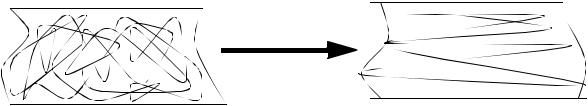
•Fibres have very long lengths with respect to the surrounding material, and tend to have a significantly higher strength along their length.
•Fibres are often drawn to align the molecules along the fibre length
page 319
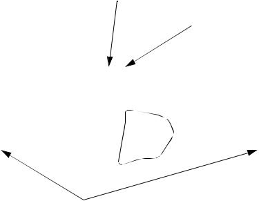
Fibre
Drawing
a stretch causing plastic deformation
undirected molecules |
directed molecules |
|
•Glass fibres are basically made by,
1.Mixing silica sand, limestone, boric acid, and other minor ingredients
2.The mixture is heated until it melts at about 2300F/1260C
3.Letting the molten glass flow through fine holes (in a platinum plate)
4.The glass strands are cooled, gathered and wound. (protective coatings may be added.)
5.The fibres are drawn to increase the directional strength.
6.The fibres are woven into various forms for use in composites
•There are three common glass types used, E, S, C
E - less expensive
S - 40% stronger than E, and more resistant to temperature
C - well suited to corrosive environments
page 320
Property |
Type of glass |
|
|
||||
|
|
|
|
|
|
||
|
|
|
|
|
|
|
|
|
|
|
C |
E |
S |
||
Density(g/cc) |
2.49-2.50 |
2.54-2.62 |
2.48-2.50 |
|
|||
|
|
|
|
||||
Tensile Strength (ksi) |
440-480 |
500 |
665 |
|
|||
@72F |
|
|
|||||
|
- |
380 |
545-645 |
|
|||
@700F |
|
||||||
- |
250 |
350 |
|
||||
@1000F |
|
||||||
|
|
|
|
||||
Tensile Modulus (Msi) |
10.0 |
10.5 |
12.4 |
|
|||
@72F |
|
|
|||||
|
- |
11.8 |
12.9 |
|
|||
@1000F |
|
||||||
|
|
|
|
||||
Coef. of thermal expansion |
4.0 |
2.8 |
3.1 |
|
|||
(in/in/F) |
|
||||||
|
|
|
|
||||
Coef. of thermal conductivity |
- |
72 |
- |
|
|||
(BTU-m/hr/sq.ft./F) |
|
||||||
0.188-0.212 |
0.193-0.197 |
0.176 |
|
||||
Specific Heat, @72F |
|
||||||
1380-1382 |
1545-1555 |
1778 |
|
||||
Softening Point, (F) |
|
||||||
- |
262-498 |
330 |
|
||||
Dielectric Strength, V/mil |
|
||||||
|
|
|
|
||||
Dielectric Constant |
- |
0.003-0.005 |
0.003-0.013 |
||||
@ 60 H2 |
|||||||
0.008 |
0.002-0.0025 |
0.003-0.0034 |
|||||
@10 |
6 |
H2 |
|||||
|
1.532 |
1.547-1.562 |
1.523-1.525 |
||||
Index of refraction |
|||||||
|
|
|
|
||||
Chemical resistance |
|
|
|
|
|||
(% weight gain after 24 hr expose.) |
1.1 |
0.7 |
0.7 |
|
|||
In H2O |
|
||||||
4.1 |
42 |
3.8 |
|
||||
In 10% HCl |
|
||||||
2.2 |
39 |
4.1 |
|
||||
In 10% H2SO4 |
|
||||||
24 |
2.1 |
2.0 |
|
||||
In 1% Na2CO3 |
|
||||||
|
|
|
|
||||
• Carbon Fibres are among the highest strength and modulus materials known.
page 321
Fibre |
Typical |
Specific |
Tensile |
Tensile |
Strain |
Coeff. of |
Poisson’s |
|
diameter |
Gravity |
modulus |
Strength |
to |
thermal exp. |
ration |
|
(micro m) |
|
(GPa) |
(GPa) |
failure |
(micro m/C) |
|
|
|
|
|
|
(%) |
(0 - 100C) |
|
|
|
|
|
|
|
|
|
Glass |
|
|
|
|
|
|
|
E glass |
10 |
2.54 |
72.4 |
3.45 |
4.8 |
5 |
0.2 |
S glass |
10 |
2.49 |
86.9 |
4.30 |
5.0 |
2.9 |
0.22 |
PAN-carbon |
|
|
|
|
|
|
|
T-300c |
7 |
1.76 |
228 |
3.2 |
1.4 |
-0.1to-0.5 |
0.2 |
ASd |
7 |
1.77 |
220 |
3.1 |
1.2 |
-0.5to-1.2 |
|
T-40c |
6 |
1.81 |
276 |
5.65 |
2 |
|
|
HMSd |
7 |
1.85 |
344.5 |
2.34 |
0.58 |
|
|
GY-70e |
8.4(bilobal) |
1.96 |
483 |
1.52 |
0.38 |
|
|
Pitch-carbon |
|
|
|
|
|
|
|
P-55c |
10 |
2.0 |
380 |
1.90 |
0.5 |
-0.9 |
|
P-100c |
10 |
2.15 |
690 |
2.2 |
0.31 |
-1.6 |
|
Kevlar 49f |
11.9 |
1.45 |
131 |
3.62 |
2.8 |
-2 |
0.35 |
Boron |
140 |
2.7 |
393 |
3.1 |
0.79 |
5 |
0.2 |
SiC |
133 |
3.08 |
400 |
3.44 |
0.84 |
1.5 |
|
Al2O3 |
20 |
3.95 |
379.3 |
1.90 |
0.4 |
8.3 |
|
|
|
|
|
|
|
|
|
• Aramids (Kevlar) fibres are shown below. These do not need to be drawn as they are already in the correct orientation when produced.
|
|
|
|
|
|
|
|
O |
|
|
|
O |
|
|
|
|
|
|
|
|
|
O |
|
|
|
|
|
O |
|
|
|
|
|
|
|
|
|
|
|
|
|
|
|
|
|
|
|||||||||||||||
|
N |
|
|
|
N |
|
|
C |
|
|
|
C |
|
N |
|
|
|
N |
|
|
|
C |
|
|
|
|
|
C |
|
|
|
|
|
|
|
|
|
|
|
|
|
|
|
|
|
|
|
|
|
|
|
|
|
||||||||
|
|
|
|
|
|
|
|
|
|
|
|
|
|
|
|
|
|
n |
||||||||||||
|
|
|
|
|
|
|
|
|
|
|
|
|
|
|
|
|
|
|
|
|
|
|
|
|
|
|
|
|
|
|
|
|
|
|
|
|
|
|
|
|
|
|
|
|
|
|
|
|
|
|
|
|
|
|
|
||||||
|
H |
|
|
|
H |
|
|
|
|
|
H |
|
|
|
H |
|
|
|
|
|
|
|
|
|||||||
|
|
|
|
|
|
|
|
|
|
|
|
|
|
O |
|
|
|
O |
|
|
|
|
|
|
|
|
|
|
||
|
|
|
|
|
|
|
|
|
|
|
|
|
|
|
|
|
|
|
|
|
|
|
|
|
|
|
||||
|
|
|
|
|
|
|
|
|
|
|
|
|
|
|
|
|
|
|
|
|
|
|
|
|
|
|
||||
|
|
|
|
|
|
|
|
|
|
|
|
|
|
|
|
|
|
|
|
|
|
|
|
|
|
|
||||
|
|
|
|
|
|
|
|
|
|
|
|
|
|
|
|
|
|
|
|
|
|
|
|
|
|
|
||||
|
|
|
|
|
|
|
|
|
|
|
|
|
|
|
|
|
|
|
|
|
|
|
|
|
|
|
||||
|
|
|
|
|
|
|
|
|
|
|
|
|
|
|
|
|
|
|
|
|
|
|
|
|
|
|||||
|
|
|
|
|
|
|
|
|
|
|
N |
|
C |
|
|
|
C |
|
|
|
|
|
|
|
|
|
|
|
||
|
|
|
|
|
|
|
|
N |
|
|
|
|
|
|
|
|
|
|
|
|
|
|
|
|
|
|
|
|||
|
|
|
|
|
|
|
|
|
|
|
|
|
|
|
|
n |
|
|
|
|
|
|
|
|
||||||
|
|
|
|
|
|
|
|
|
|
|
|
|
|
|
|
|
|
|
|
|
|
|
|
|
|
|
|
|||
|
|
|
|
|
|
|
|
|
|
|
|
|
|
|
|
|
|
|
|
|
|
|
|
|
|
|
|
|
|
|
|
|
|
|
|
|
|
H |
|
|
|
H |
|
|
|
|
|
|
|
|
|
|
|
|
|
|
|
|
|
|
|
•aramid fibres come in bundles of 134 to 10,000 filaments
•kevlar properties are,
page 322
Kevlar # |
29 |
49 |
149 |
Tensile modulus (MPa) |
83 |
131 |
186 |
Tensile strength (Mpa) |
3.6 |
3.6 |
3.4 |
Elongation (%) |
4 |
2.8 |
2 |
Density (g/cc) |
1.44 |
1.44 |
1.47 |
|
|
|
|
• Other popular fibre types are Boron, Silicon, Carbide, Alumina, etc.
•The fibres come in a variety of configurations, Filament - a single fibre
Strand - Could refer to a single fibre, or an untwisted bundle of filaments Tow - A bundle of untwisted fibres, often a predetermined number.
Yarn - A twisted tow
Roving - A number of yarns pulled together without twisting Tape - a thin and wide run of parallel fibres
Woven fabric - yarns and tows are interlaced to create flat cloth Braids - yarns and tows are woven into tubular shapes
Mat - chopped fibres create an undirected pattern in a flat cloth. A binder holds the fibres together.
•There are different weave types used, these provide different workabilities, air removal, distortions, etc.
|
|
|
|
|
|
|
|
|
|
|
|
|
|
|
|
|
|
|
|
|
|
|
|
|
|
|
|
|
|
|
|
|
|
|
|
|
|
|
|
|
|
|
|
|
|
|
|
|
|
|
|
|
|
|
|
|
|
|
|
|
|
|
|
|
|
|
|
|
|
|
|
|
|
|
|
|
|
|
|
|
|
|
|
|
|
|
|
|
|
|
|
|
|
|
|
|
|
|
|
|
|
|
|
|
|
|
|
|
|
|
|
|
|
|
|
|
|
|
|
|
|
|
|
|
|
|
|
|
|
|
|
|
|
|
|
|
|
|
|
|
|
|
|
|
|
|
|
|
|
|
|
|
|
|
|
|
|
|
|
|
|
|
|
|
|
|
|
|
|
|
|
|
|
|
|
|
|
|
|
|
|
|
|
|
|
|
|
|
|
|
|
|
|
|
|
|
|
|
|
|
|
|
|
|
|
|
|
|
|
|
|
|
|
|
|
|
|
|
|
|
|
|
|
|
|
|
|
|
|
|
|
|
|
|
|
|
|
|
|
|
|
|
|
|
|
|
|
|
|
|
|
|
|
|
|
|
|
|
|
|
|
|
|
|
|
|
|
|
|
|
|
|
|
|
|
|
|
|
|
|
|
|
|
|
|
|
|
|
|
|
|
|
|
|
|
|
|
|
|
|
|
|
|
|
|
|
|
|
|
|
|
|
|
|
|
|
|
|
|
|
|
|
|
|
|
|
|
|
|
|
|
|
|
|
|
|
|
|
|
|
|
|
|
|
|
|
|
|
|
|
|
|
|
|
|
|
|
|
|
|
|
|
|
|
|
|
|
|
|
|
|
|
|
|
|
|
|
|
|
|
|
|
|
|
|
|
|
|
|
|
|
|
|
|
|
|
|
|
|
|
|
|
|
|
|
|
|
|
|
|
|
|
|
|
|
|
|
|
|
|
|
|
|
|
|
|
|
|
|
|
|
|
|
|
|
|
|
|
|
|
|
|
|
|
|
|
|
|
|
|
|
|
|
|
|
|
|
|
|
|
|
|
|
|
|
|
|
|
|
|
|
|
|
|
|
|
|
|
|
|
|
|
|
|
|
|
|
|
|
|
|
|
|
|
|
|
|
|
|
|
|
|
|
|
|
|
|
|
|
|
|
|
|
|
|
|
|
|
|
|
|
|
|
|
|
|
|
|
|
|
|
|
|
|
|
|
|
|
|
|
|
|
|
|
|
|
|
|
|
|
|
|
|
|
|
|
|
|
|
|
|
|
|
|
|
|
|
|
|
|
|
|
|
|
|
|
|
|
|
|
|
|
|
|
|
|
|
|
|
|
|
|
|
|
|
|
|
|
|
|
|
|
|
|
|
|
|
|
|
|
|
|
|
|
|
|
|
|
|
|
|
|
|
|
|
|
|
|
|
|
|
|
|
|
|
|
|
|
|
|
|
|
|
|
|
|
|
|
|
|
|
|
|
|
|
|
|
|
|
|
|
|
|
|
|
|
|
|
|
|
|
|
|
|
|
|
|
|
|
|
|
|
|
|
|
|
|
|
|
|
|
|
|
|
|
|
|
|
|
|
|
|
|
|
|
|
|
|
|
|
|
|
|
|
|
|
|
|
|
|
|
|
|
|
|
|
|
|
|
|
|
|
plain weave |
|
|
basket weave |
|||||||||||||||||||||||||||||||||||||
page 323
crowfoot satin
long-shaft
•weaves can be made from single fibre types, or combinations
•The relative material properties for composites are seen in the figures below RTW - Rigidity to weight
STW - strength to weight Strain - failure strain
UTS - ultimate tensile strength Yield - yield strength
USS - Ultimate shear strength
UCS - Ultimate compressive strength
page 324
Material |
Spec.E |
G |
UTS |
YieldRTW STW |
StrainPoissThermUSS UCS |
||||
|
Grav.(GPa GPa |
(GPa)(MPa) |
|
(%) |
|
(MPa)(MPa) |
|||
|
|
|
|
|
|
|
|
|
|
Boron & epoxy 1.99 207 |
6.4 |
1585 |
|
|
0.5 |
.21 |
|
2482 |
|
(unidirectional, along fiber) |
|
|
|
|
|
|
|||
Boron & epoxy 1.99 19 |
|
62.7 |
|
|
0.5 |
.21 |
|
|
|
(unidirectional, across fiber) |
|
|
|
|
|
|
|||
boron 6061 & Al2.35220 |
|
1109 |
na |
9.54 48.1 |
0.5 |
|
|
|
|
(unidirectional, along fiber) |
|
|
|
|
|
|
|||
carbon & epoxy1.55 137.85.7 |
1550 |
na |
9.06 101.91.4 |
.25 |
60 |
1172 |
|||
(high strength, unidirectional, along fiber) |
|
|
|
|
|||||
carbon & epoxy1.55 9.0 |
|
|
na |
|
|
.25 |
|
|
|
(high strength, unidirectional, across fiber) |
|
|
|
|
|||||
carbon & epoxy1.63 215 |
5.9 |
1240 |
na |
13.4477.5 |
0.4 |
.2 |
72 |
620 |
|
(high modulus, unidirectional, along fiber) |
|
|
|
|
|||||
carbon & epoxy1.63 13.8 |
|
86.2 |
na |
|
|
.2 |
|
|
|
(high modulus, unidirectional, across fiber) |
|
|
|
|
|||||
carbon & epoxy1.55 45.5 |
|
579 |
na |
2.99 38 |
|
|
|
|
|
(quasi-isotropic) |
|
|
|
|
|
|
|
|
|
E-glass & epoxy1.8039.3 4.8 |
965 |
na |
2.16 53.2 |
5 |
.3 |
83 |
620 |
||
(unidirectional, along fiber) |
|
|
|
|
|
|
|||
E-glass & epoxy1.804.8 |
|
96.5 |
na |
|
5 |
.3 |
|
|
|
(unidirectional, across fiber) |
|
|
|
|
|
|
|||
GY-70 & epoxy 1.69 276 |
4.1 |
586 |
|
|
0.3 |
.25 |
96.5 |
517 |
|
(unidirectional, along fiber) |
|
|
|
|
|
|
|||
GY-70 & epoxy 1.69 8.3 |
|
41.3 |
|
|
0.3 |
.25 |
|
|
|
(unidirectional, across fiber) |
|
|
|
|
|
|
|||
kevlar49 & epoxy1.3875.82.1 |
1378 |
na |
5.60 101.83.1 |
.34 |
60 |
276 |
|||
(unidirectional, along fiber) |
|
|
|
|
|
|
|||
kevlar49 & epoxy1.385.5 |
|
28.3 |
na |
|
3.1 |
.34 |
|
|
|
(unidirectional, across fiber) |
|
|
|
|
|
|
|||
S-glass & epoxy1.8243 |
|
1241 |
na |
|
5 |
|
83 |
758 |
|
(unidirectional, along fiber) |
|
|
|
|
|
|
|||
T300 & epoxy 1.55 138 |
6.5 |
1448 |
|
|
1 |
.21 |
62 |
1448 |
|
(unidirectional, along fiber) |
|
|
|
|
|
|
|||
T300 & epoxy |
1.55 10 |
|
44.8 |
|
|
1 |
.21 |
|
|
•Composites are sensitive to temperature and humidity during curing.
•When dealing with cyclic loading over a million cycles
-Aluminum and steel design with 0.1 of the normal yield strength
-Composites design with 0.5 of normal yield strength
•Composites in general are very easy to shape, and form, this is not always possible with other high strength materials
•Composites are anisotropic and have good strength along the fibre length, but reduced strength across the fibre axis.
•Elongation of composites is typically linear up to fracture at 1% to 2% elongation