


page 25
|
α |
t2 |
|
the shear plane |
|
|
tool |
Fs |
φ |
t1 |
|
Fc |
|
Fn |
|
R |
|
Ft |
|
τ |
F |
|
|
N |
|
Fs = shear force
Fn = force normal to shear plane
α = tool rake angle (positive as shown) φ = shear angle
τ = friction angle
5.3 POWER CONSUMED IN CUTTING
•There are a number of reasons for wanting to calculate the power consumed in cutting. These numbers can tell us how fast we can cut, or how large the motor on a machine must be.
•Having both the forces and velocities found with the Merchant for Circle, we are able to calculate the power,

page 26
Pc |
= |
FcVc |
|
-------------- |
|
||
|
|
33000 |
|
Ps |
= |
FsVs |
All have units of Horsepower (i.e., 1/33000) |
-------------- |
|||
|
|
33000 |
|
Pf |
= |
F × Vf |
|
-------------- |
|
||
|
|
33000 |
|
where,
Pc = the total cutting power
Ps = the shearing power required Pf = the friction losses
• We can relate the energy used in cutting to the mrr.
Energy Consumed |
Pc = Fc × Vc |
Metal Removal Rate |
Q = A0 × Vc |
where,
A0 = Area of Cut
***Note: both Wc and Q are proportional to Vc
From these basic relationships we can a simple relationship that is the ratio between the energy consumed, and the volume of metal removed,
ps = |
Pc |
= |
Fc |
× |
Vc |
= |
Fc |
----- |
----------------- |
----- |
|||||
|
Q |
|
A0 |
× |
Vc |
|
A0 |
You will notice that the result is a force over an area, which is a pressure. As a result Ps will be called the Specific Cutting Pressure.
• The cutting force will vary, thus changing Ps, as the cutting velocities are changed.

page 27
ps |
Vc |
This curve turns downward for two reasons,
1.The tool experiences edge forces that are more significant at lower cutting speeds.
2.As the velocity increases, the temperature increases, and less energy is required to shear the metal.
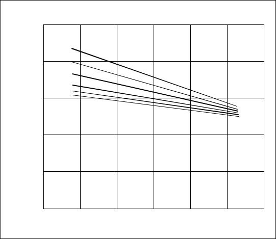
•Tool hardness is degraded by temperature, as shown in the diagram below [REF]
A Comparison of how the hardness of cutting-tool materials is affected by temperature
A) |
100 |
|
|
|
|
|
|
|
|
|
|
|
|
|
|
|
|
|
|
(Rockwell |
90 |
|
|
|
|
|
|
|
|
|
|
|
|
|
|
oxide |
|
||
80 |
|
|
|
|
|
|
|
|
|
Hardness |
|
|
|
|
|
|
|
carbide |
|
|
|
|
|
|
|
|
|
||
70 |
|
|
|
|
|
|
|
cast alloy |
|
|
|
|
|
|
|
|
|
||
|
60 |
|
|
high carbon steel |
|
high speed steel |
|||
|
|
|
|
|
|
|
|||
|
|
|
|
|
|
|
|
|
|
|
0 |
200 |
400 |
600 |
800 |
1000 |
1200 |
1400 |
1600 |
Temperature (°F)
page 28
• The effects of rake angle on cutting are shown in the graph below, [REF ******]
The Effect of Rake Angle on Cutting Force
|
500 |
|
|
|
|
|
|
|
|
fpm |
|
|
|
|
|
|
|
150 |
|
|
|
|
|
|
400 |
200 |
|
|
|
|
|
Cutting |
|
300 |
|
|
|
|
|
|
400 |
|
|
|
|
|
|
300 |
500 |
|
|
|
|
|
|
600 |
|
|
|
|
|
||
(F Force |
|
|
|
|
|
|
|
c |
200 |
|
|
|
|
|
|
) |
|
|
|
|
|
|
|
).(lb |
|
|
|
|
|
|
|
|
|
|
|
|
|
|
|
|
100 |
|
Carbide Tool |
|
|
|
|
|
|
|
|
|
|
|
|
|
|
|
Feed = 0.010”/rev. |
|
|
|
|
|
0 |
|
|
|
|
|
|
|
15°- |
10°- |
5°- |
0° |
5° |
10° |
15° |
Rake Angle
• The horsepower required for cutting can be found using empirical methods,

page 29
Unit horse power (HPu) is the amount of power to remove a volume of metal in a period of time.
HPu = power to cut 1 cubic inch per minute - found in tables
HPg = Q × HPu = Gross Horsepower
Average Unit Horsepower Values of Energy Per Unit Volume [REF]
Material |
|
BHN |
|
HP (HP/(in3/min.) |
|
|
|||
|
|
|
|
u |
Carbon steels |
|
150-200 |
|
1.0 |
|
|
200-250 |
|
1.4 |
|
|
250-350 |
|
1.6 |
Leaded steels |
|
150-175 |
|
0.7 |
Cast irons |
|
125-190 |
|
0.5 |
|
|
190-250 |
|
1.6 |
Stainless steels |
|
135-275 |
|
1.5 |
Aluminum alloys |
|
50-100 |
|
0.3 |
Magnesium alloys |
|
40-90 |
|
0.2 |
Copper |
|
125-140 |
|
0.7 |
Copper alloys |
|
100-150 |
|
0.7 |
|
|
• If we consider the implications these formulas have when cutting on a lathe, we would be able to develop the following equations,

page 30
Q = f × d × V × 12
where,
f = feed
d = depth or cut V = velocity
HPc |
Fc × Vc |
= HPu × Q × c |
= ----------------- |
||
|
33000 |
|
where,
c = a feed factor from tables
Horsepower Feed Correction Factors for Turning, Planning and Shaping [RE
Feed |
|
Factor |
|
|
|
|
|
(ips or ipr) |
|
(mm/rev or mm/stroke) |
|
|
|
|
|
0.002 |
|
0.05 |
1.4 |
0.005 |
|
0.12 |
1.2 |
0.008 |
|
0.20 |
1.05 |
0.012 |
|
0.30 |
1.0 |
0.020 |
|
0.50 |
0.9 |
0.030 |
|
0.75 |
0.80 |
0.040 |
|
1.00 |
0.80 |
0.050 |
|
1.25 |
0.75 |