
- •1. TABLE OF CONTENTS
- •2. BASIC CIRCUIT ANALYSIS
- •2.1 CIRCUIT COMPONENTS AND QUANTITIES
- •2.2 CIRCUIT DIAGRAMS
- •3. CIRCUIT ANALYSIS
- •3.1 KIRCHOFF’S LAWS
- •3.1.1 Simple Applications of Kirchoff’s Laws
- •3.1.1.1 - Parallel Resistors
- •3.1.1.2 - Series Resistors
- •3.1.2 Node Voltage Methods
- •3.1.3 Current Mesh Methods
- •3.1.4 More Advanced Applications
- •3.1.4.1 - Voltage Dividers
- •3.1.4.2 - The Wheatstone Bridge
- •3.1.4.3 - Tee-To-Pi (Y to Delta) Conversion
- •3.2 THEVENIN AND NORTON EQUIVALENTS
- •3.2.1 Superposition
- •3.2.2 Maximum Power Transfer
- •3.3 CIRCUITS CONTAINING CAPACITORS AND INDUCTORS
- •4. PASSIVE DEVICES
- •4.1 TRANSFORMERS
- •5. ACTIVE DEVICES
- •5.1 OPERATIONAL AMPLIFIERS
- •5.1.1 General Details
- •5.1.2 Simple Applications
- •5.1.2.1 - Inverting Amplifier
- •5.1.2.2 - Non-Inverting Amplifier
- •5.1.2.3 - Integrator
- •5.1.2.4 - Differentiator
- •5.1.2.5 - Weighted Sums
- •5.1.2.6 - Difference Amplifier (Subtraction)
- •5.1.2.7 - Op-Amp Voltage Follower
- •5.1.2.8 - Bridge Balancer
- •5.1.2.9 - Low Pass Filter
- •5.1.3 Op-Amp Equivalent Circuits
- •5.1.3.1 - Frequency Response
- •5.2 TRANSISTORS
- •5.2.1 Bipolar Junction Transistors (BJT)
- •5.2.1.1 - Biasing Common Emitter Transistors
- •6. AC CIRCUIT ANALYSIS
- •6.1 PHASORS
- •6.1.1 RMS Values
- •6.1.2 LR Circuits
- •6.1.3 RC Circuits
- •6.1.4 LRC Circuits
- •6.1.5 LC Circuits
- •6.2 AC POWER
- •6.2.1 Complex Power
- •6.2.1.1 - Real Power
- •6.2.1.2 - Average Power
- •6.2.1.3 - Reactive Power
- •6.2.1.4 - Apparent Power
- •6.2.1.5 - Complex Power
- •6.2.1.6 - Power Factor
- •6.2.1.7 - Average Power Calculation
- •6.2.1.8 - Maximum Power Transfer
- •6.3 3-PHASE CIRCUITS
- •7. TWO PORT NETWORKS
- •7.1 PARAMETER VALUES
- •7.1.1 z-Parameters (impedance)
- •7.1.2 y-Parameters (admittance)
- •7.1.3 a-Parameters (transmission)
- •7.1.4 b-Parameters (transmission)
- •7.1.5 h-Parameters (hybrid)
- •7.1.6 g- Parameters (hybrid)
- •7.2 PROPERTIES
- •7.2.1 Reciprocal Networks
- •7.2.2 Symmetrical Networks
- •7.3 CONNECTING NETWORKS
- •7.3.1 Cascade
- •7.3.2 Series
- •7.3.3 Parallel
- •7.3.4 Series-Parallel
- •7.3.5 Parallel-Series
- •8. CAE TECHNIQUES FOR CIRCUITS
- •9. A CIRCUITS COOKBOOK
- •9.1 HOW TO USE A COOKBOOK
- •9.2 SAFETY
- •9.3 BASIC NOTES ABOUT CHIPS
- •9.4 CONVENTIONS
- •9.5 USEFUL COMPONENT INFORMATION
- •9.5.1 Resistors
- •9.5.2 Capacitors
- •9.6 FABRICATION
- •9.6.1 Shielding and Grounding
- •9.7 LOGIC
- •9.8 ANALOG SENSORS
page 13
• Kirchoff’s Voltage Law: “The sum of all voltages about a closed loop in a circuit is equal to zero” - Each element will have a voltage (potential) between nodes. If any two points on the closed loop are chosen, and different paths chosen between them, the potentials must be equal or current will flow in a loop indefinately (Note: this would be perpetual motion).
3.1.1 Simple Applications of Kirchoff’s Laws
3.1.1.1 - Parallel Resistors
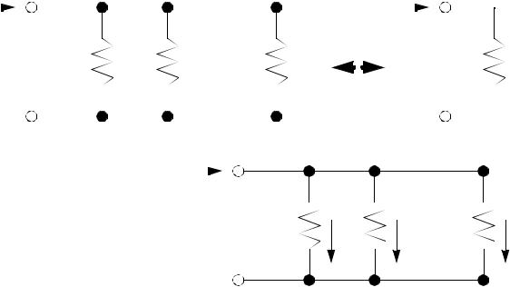
• Let’s consider one on the most common electrical calculations - that for resistors in parallel. We want to find the equivalent resistance for the network of resistors shown.

page 14
I |
|
|
|
|
|
I |
|||||
|
+ |
|
|
|
|
|
+ |
Rp |
|||
|
|
|
R1 |
R2 |
Rn |
|
|
|
|
|
|
|
|
|
|
|
|
|
|
|
|||
|
|
V |
|
|
|
|
|
|
V |
||
|
|
|
|
|
|
|
|
||||
- |
|
|
|
- |
|
||||||
|
|
|
|
||||||||
|
|
|
|
|
|
|
|
|
|
|
|
|
|
|
|
|
|
|
|
|
|
|
|
First we can define cur- |
I |
rents in each branch of |
|
the circuit. Also recog- |
|
nize that the potential |
|
voltage across each |
|
resistor will be V. |
|
+
R1 |
R2 |
Rn |
V
I1 I2
In
-
Now, consider the sum of the currents in and out of the upper conductor,
∑ I = I – I1 – I2 – … – In = 0
The current through each resistor is simple to calculate, so if we add the current through the resistors, and then relate the expression to Rp, the equation becomes,
I – |
-----V – -----V – … |
– |
-----V = 0 |
|
|
|
||||||
|
|
R1 |
R 2 |
|
|
Rn |
|
|
|
|
||
|
I |
= |
|
1 |
+ |
1 |
+ … |
+ |
1 |
= |
1 |
|
-- |
|
----- |
R-----2 |
R-----n |
----- |
|||||||
|
V |
|
R 1 |
|
|
|
|
|
Rp |
|||
|
|
|
|
|
|
|
|
|
|
|
|
|
|
Rp |
= |
|
|
|
|
1 |
|
|
|
|
|
|
------------------------------------------- 1 |
+ |
1 |
+ … |
+ |
1 |
|
|
|
|||
|
|
|
----- ----- |
----- |
R2 |
Rn |
|
|
|
|||
|
|
|
|
R 1 |
|
|
|
|
|
|
3.1.1.2 - Series Resistors
• Now consider another problem with series resistors. We can use Kirchoff’s voltage law to sum the voltages in the circuit loop. In this case the input voltage is a voltage rise, and the resistors are voltage drops (the signs will be opposite).