


page 88
•Shielding is important for all circuits, it prevents electrical noise from creating false digital signals, and from corrupting analog signals.
•Shielding is accomplished through a number of methods:
-sheet metal (iron) enclosures keep electromagnetic interference out, or in.
-shielded cables
-RF chokes
-bypass capacitors
•Cables can be shielded two different ways:
-twisted pairs - two wires that are used for a signal (signal and common) are twisted once per inch or more. As a result, any inductive magnetic field induces a current one way for one twist, and the other way for the next twist - hence cancelling out the induced current.
-shielding sheaths - cable bundles are often covered by a metal foil, or braided wire to provide a general protection for the cable. This shield is to be connected at one end (not two) of the cable to drain off any induced currents.
reinforcing fiber (optional) twisted pair
shield insulation
9.7 LOGIC
• Decimal to binary encoder

page 89
+V
1
2
3
4
5
6
7
8
9
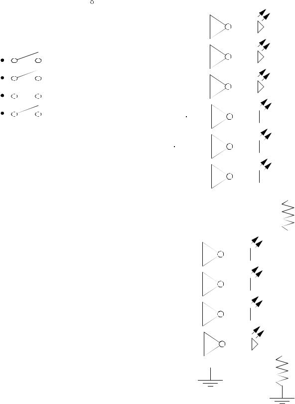
• Binary to decimal decoder
11
12
13
1
2
3
4
5
10
74147 |
|
7404 |
|
|
|
|
|
9 |
20 |
1 |
2 |
7 |
21 |
3 |
4 |
6 |
22 |
5 |
6 |
14 |
23 |
7 |
8 |
8 |
|
14 |
|
220
page 90
|
|
|
|
+V |
|
|
|
|
|
|
|
|
|
|
|
|
|
|
|
|
|
|
|
|
|
|
|
|
|
|
|
|
|
|
|
|
|
|
|
|
|
|
|||||||
|
|
|
|
|
|
|
|
|
|
|
|
|
|
|
|
7404 |
|
|
|
|
|
|
|
|
|
|
|
|
|
|
|
|
|
|
|
|
|
|
|||||||||||
|
|
|
|
|
|
|
|
|
|
|
|
|
|
|
|
|
|
|
|
|
|
|
|
|
|
|
|
|
|
|
|
|
|
|
|
|
|
|
|
|
|
|
|
|
|
|
|||
|
|
|
|
|
|
|
|
|
|
|
|
|
|
|
|
|
|
|
|
|
|
|
|
|
1 |
|
|
|
|
2 |
|
|
|
|
|
|
|
|
|
|
|
|
|
|
|
|
|||
|
|
|
|
|
|
|
|
|
|
|
|
|
|
|
|
|
|
|
|
|
|
|
|
|
|
|
|
|
|
|
|
|
|
|
|
|
|
|
|
|
|||||||||
|
|
|
|
|
|
|
|
|
|
|
|
|
|
|
|
|
|
|
|
|
|
|
|
|
3 |
|
|
|
|
4 |
|
|
|
|
|
|
|
|
|
|
|
|
|
|
|
|
|||
|
|
|
|
|
|
|
|
|
|
|
|
|
|
|
|
|
|
|
|
|
|
|
|
|
|
|
|
|
|
|
|
|
|
|
|
|
|
|
|
|
|
|
|
|
|||||
|
20 |
|
15 |
7442 |
|
|
|
|
|
|
|
|
|
|
|
|
|
|
|
|
|
|
|
|
|
|
|
|
|
|
|
|
|
|
|
|
|||||||||||||
|
|
|
|
|
|
|
|
|
|
|
|
|
|
|
|
|
|
|
|
|
|
|
|
|
|
|
|
|
|
||||||||||||||||||||
|
|
|
|
|
|
|
|
|
|
|
|
|
|
|
|
|
|
|
|
|
|
|
|
|
|
|
|
|
|
|
|
|
|
|
|
|
|
|
|
||||||||||
|
|
14 |
1 |
|
|
|
|
|
|
|
|
|
|
|
|
|
|
|
|
|
|
|
|
|
|
|
|
|
|
|
|
|
|
|
|
|
|
|
|
||||||||||
|
|
|
|
|
|
|
|
|
|
|
|
|
|
|
|
|
|
|
|
|
|
|
|
|
|
|
|
|
|
|
|
|
|
|
|
|
|||||||||||||
|
21 |
|
2 |
|
|
|
|
|
|
|
|
|
|
|
5 |
|
|
|
|
6 |
|
|
|
|
|
|
|
|
|
|
|
|
|
|
|
|
|||||||||||||
|
|
|
|
|
|
|
|
|
|
|
|
|
|
|
|
|
|
|
|
|
|
|
|
|
|
|
|
|
|
|
|
|
|||||||||||||||||
|
|
13 |
3 |
|
|
|
|
|
|
|
|
|
|
|
|
|
|
|
|
|
|
|
|
|
|
|
|
|
|
|
|
|
|
|
|||||||||||||||
|
|
|
|
|
|
|
|
|
|
|
|
|
|
|
|
|
|
|
|
|
|
|
|
|
|
|
|
||||||||||||||||||||||
|
22 |
|
|
|
|
|
|
|
|
|
|
|
|
|
|
|
|
|
|
|
|
|
|
|
|
|
|
|
|
|
|
|
|
|
|
|
|
|
|||||||||||
|
|
4 |
|
|
|
|
|
|
|
|
|
|
|
|
|
|
|
|
|
|
|
|
|
|
|
|
|
|
|
|
|
|
|
|
|
|
|
|
|||||||||||
|
|
12 |
|
|
|
|
|
|
|
|
|
|
|
|
|
|
|
|
|
|
|
|
|
|
|
|
|
|
|
|
|
|
|
|
|
|
|
|
|||||||||||
|
|
|
|
|
|
|
|
|
|
|
|
|
|
|
|
|
|
|
|
|
|
|
|
|
|
|
|
|
|
|
|
|
|
|
|
|
|||||||||||||
|
|
|
5 |
|
|
|
|
|
|
|
|
|
|
|
7 |
|
|
|
|
8 |
|
|
|
|
|
|
|
|
|
|
|
|
|
|
|
|
|||||||||||||
|
|
|
|
|
|
|
|
|
|
|
|
|
|
|
|
|
|
|
|
|
|
|
|
|
|
|
|
|
|
|
|
|
|
||||||||||||||||
23 |
|
|
|
|
|
||||||||||||||||||||||||||||||||||||||||||||
|
|
6 |
|
|
|
|
|
|
|
|
|
|
|
|
|
|
|
|
|
|
|
|
|
|
|
|
|
|
|
|
|
|
|
|
|
|
|
|
|||||||||||
|
|
|
|
|
|
|
|
|
|
|
|
|
|
|
|
|
|
|
|
|
|
|
|
|
|
|
|
|
|
|
|
|
|
|
|
|
|
|
|
||||||||||
|
|
|
|
7 |
|
|
|
|
|
|
|
|
|
|
|
9 |
|
|
|
|
10 |
|
|
|
|
|
|
|
|
|
|
|
|
|
|
|
|
||||||||||||
|
|
|
|
|
|
|
|
|
|
|
|
|
|
|
|
|
|
|
|
|
|
|
|
|
|
|
|
|
|
|
|
|
|
|
|||||||||||||||
|
|
|
|
9 |
|
|
|
|
|
|
|
|
|
|
|
|
|
|
|
|
|
|
|
|
|
|
|
|
|
|
|
|
|
|
|
||||||||||||||
|
|
|
|
|
|
|
|
|
|
|
|
|
|
|
|
|
|
|
|
|
|
|
|
|
|
|
|
|
|
|
|||||||||||||||||||
|
|
|
|
|
|
|
|
|
|
|
|
|
|
|
|
|
|
|
|
|
|
|
|
|
|
|
|
|
|
|
|
|
|
|
|
|
|
|
|
||||||||||
|
|
|
|
10 |
|
|
|
|
|
|
|
|
|
|
|
|
|
|
|
|
|
|
|
|
|
|
|
|
|
|
|
|
|
|
|
|
|
|
|
|
|||||||||
|
|
|
|
|
|
|
|
|
|
|
|
|
|
|
|
|
|
|
|
|
|
|
|
|
|
|
|
|
|
|
|
|
|
|
|
|
|
|
|
||||||||||
|
|
|
|
11 |
|
|
|
|
|
|
|
|
|
|
|
11 |
|
|
|
|
12 |
|
|
|
|
|
|
|
|
|
|
|
|
|
|
|
|
||||||||||||
|
|
|
|
|
|
|
|
|
|
|
|
|
|
|
|
|
|
|
|
|
|
|
|
|
|
|
|
|
|
|
|||||||||||||||||||
|
|
|
|
|
|
|
|
|
|
|
|
|
|
|
|
|
|
|
|
|
|
|
|
|
14 |
|
|
|
|
|
|
|
|
|
|
|
|
|
|
|
|
|
|
|
|
|
|||
|
|
|
|
|
|
|
|
|
|
|
|
|
|
|
|
|
|
|
|
|
|
|
|
|
|
|
|
|
|
|
|
|
|
|
|
|
|
|
|
|
|
|
|
|
|
||||
|
|
|
|
8 |
|
|
|
|
|
|
|
|
|
|
|
|
|
|
|
|
|
|
|
|
|
|
|
|
|
|
|
|
|
|
|
|
|
|
|
|
|
|
|||||||
|
|
|
|
|
|
|
|
|
|
|
|
|
|
|
|
|
|
|
|
|
|
|
|
|
|
|
|
|
|
|
220 |
|
|
|
|
|
|
||||||||||||
|
|
|
|
|
|
|
|
|
|
|
|
|
|
|
|
|
|
|
|
|
|
|
|
|
|
|
|
|
|
|
|
|
|
|
|
|
|||||||||||||
|
|
|
|
|
|
|
|
|
|
|
|
|
|
|
|
|
|
|
|
|
|
|
|
|
|
|
|
|
|
|
|
|
|
|
|
|
|||||||||||||
|
|
|
|
|
|
|
|
|
|
|
|
|
|
|
|
|
|
|
|
|
|
|
|
|
|
|
|
|
|
|
|
|
|
|
|
|
|
|
|
|
|
|
|
|
|
|
|
|
|
|
|
|
|
|
|
|
|
|
|
|
|
|
|
|
|
|
|
|
7404 |
|
|
|
|
|
|
|
|
|
|
|
|
|
|
|
|
|
|
|
|
|
|
|
|||||||
|
|
|
|
|
|
|
|
|
|
|
|
|
|
|
|
|
|
|
|
|
|
|
|
|
|
|
|
|
|
|
|
|
|
||||||||||||||||
|
|
|
|
|
|
|
|
|
|
|
|
|
|
|
|
|
|
|
|
|
|
|
|
|
|
|
|
|
|
|
|
|
|
||||||||||||||||
|
|
|
|
|
|
|
|
|
|
|
|
|
|
|
|
|
|
|
|
|
|
|
1 |
|
|
|
|
2 |
|
|
|
|
|
|
|
|
|
|
|
|
|
|
|
|
|
|
|||
|
|
|
|
|
|
|
|
|
|
|
|
|
|
|
|
|
|
|
|
|
|
|
|
|
|
|
|
|
|
|
|
|
|
|
|
|
|
|
|
|
|||||||||
|
|
|
|
|
|
|
|
|
|
|
|
|
|
|
|
|
|
|
|
|
|
|
|
|
|
|
|
|
|
||||||||||||||||||||
|
|
|
|
|
|
|
|
|
|
|
|
|
|
|
|
|
|
3 |
|
|
|
|
4 |
|
|
|
|
|
|
|
|
|
|
|
|
|
|
|
|
|
|
||||||||
|
|
|
|
|
|
|
|
|
|
|
|
|
|
|
|
|
|
|
|
|
|
|
|
|
|
|
|
|
|
|
|
|
|
|
|
|
|
|
|
||||||||||
|
|
|
|
|
|
|
|
|
|
|
|
|
|
|
|
|
|
|
|
|
|
|
|
|
|
|
|
|
|
|
|
|
|
|
|
|
|
|
|
||||||||||
|
|
|
|
|
|
|
|
|
|
|
|
|
|
|
|
|
|
|
|
|
|
|
5 |
|
|
|
|
6 |
|
|
|
|
|
|
|
|
|
|
|
|
|
|
|
|
|
|
|||
|
|
|
|
|
|
|
|
|
|
|
|
|
|
|
|
|
|
|
|
|
|
|
|
|
|
|
|
|
|
|
|
|
|
|
|
|
|
|
|
|
|
|
|
|
|||||
|
|
|
|
|
|
|
|
|
|
|
|
|
|
|
|
|
|
|
|
|
|
|
|
|
|
|
|
|
|
|
|
|
|
|
|
|
|
|
|
||||||||||
|
|
|
|
|
|
|
|
|
|
|
|
|
|
|
|
|
|
|
|
|
|
|
7 |
|
|
|
|
8 |
|
|
|
|
|
|
|
|
|
|
|
|
|
|
|
|
|
|
|||
|
|
|
|
|
|
|
|
|
|
|
|
|
|
|
|
|
|
|
|
|
|
|
|
|
|
|
|
|
|
|
|
|
|
|
|
|
|
|
|
|
|
|
|
|
|||||
|
|
|
|
|
|
|
|
|
|
|
|
|
|
|
|
|
|
|
|
|
|
|
|
|
|
|
|
|
|
|
|
|
|
|
|
|
|
|
|
||||||||||
|
|
|
|
|
|
|
|
|
|
|
|
|
|
|
|
|
|
|
|
|
|
|
14 |
|
|
|
|
|
|
|
|
|
|
|
|
|
|
|
|
|
|
|
|
|
|
|
|||
|
|
|
|
|
|
|
|
|
|
|
|
|
|
|
|
|
|
|
|
|
|
|
|
|
|
|
|
|
|
|
|
|
|
|
|
|
|
|
|
|
|
|
|
|
|
||||
|
|
|
|
|
|
|
|
|
|
|
|
|
|
|
|
|
|
|
|
|
|
|
|
|
|
|
|
|
|
|
|
|
|
|
|
|
|
|
|
|
|
|
|||||||
|
|
|
|
|
|
|
|
|
|
|
|
|
|
|
|
|
|
|
|
|
|
|
|
|
|
|
|
|
|
|
|
|
|
|
|
|
|
|
|
|
|
|
|
|
|
|
|
|
|
220
page 91
9.8 ANALOG SENSORS
• LEVEL DETECTOR LIGHT OR TEMPERATURE - To measure temperatures or light levels against one level. If measuring temperature the device should be an RTD. If measuring light the device should be a photoresistor (LDR). The value of resistor R1 should be selected to be close to the normal resistance of the device. The potentiometer can be used to make fine adjustments.
V+
10K |
- |
|
|
device |
+ |
|
Vo |
R1 |
|
V- |
|
• RANGE CONTROLLER - Upper/lower range controller. This can be done with a simple a simple flip flop. Two level detector circuits are used for the inputs. The Set value should be the upper range, the reset value should be the lower value. The output can be used to drive a relay, or some other driver.
low |
S |
Q |
|
high  R
R
• SINKING SENSOR TO TTL - To convert a sinking sensor to a TTL input. The ratio of resistors R1 and R2 is determined by the ratio between the sensor supply voltage (normally 24V) and the TTL input voltage (normally 5V). The resisto values should probably be between 1K and 10K.

page 92
+ |
power |
|
|
|
Vs |
|
|
|
|
supply |
R1 |
|
|
|
- |
|
|
||
|
|
|
|
|
V+ |
|
|
|
device |
sensor |
|
|
|
|
|
|
Vi |
with |
|
|
|
R2 |
||
|
|
TTL |
||
NPN |
|
|
||
|
|
|
||
|
|
|
inputs |
|
|
|
|
|
|
V- |
|
|
|
|
Vi |
R2 |
|
|
|
---- |
= ------------------ |
|
|
|
Vs |
R1 + R2 |
|
|
|
• MOTOR REVERSER USING RELAYS - A circuit that allows a motor to be turned on in either direction (safely). The motor on relay can be a single pole single throw (SPST), whilew the reversal relay mst be a double pole double throw (DPDT) relay. The relays should be selected to carry the peak motor currents.
motor
motor on
reverse
+motor - power supply
•DRIVING A HIGH CURRENT DC LOAD WITH A TRANSISTOR - This circuit can be used for a load that requires a few amps of power, but is being controlled by a low current TTL out-

page 93
put. The transistor must be selected so that it can carry the maximum load current. A heat sink should be used if the device will pass a large percentage of the rated current. Note that the voltage loss accross the transistor will be approximately 2V. For a higher current load a Darlington coupled transistor can be used.
|
- |
+ |
+ |
device |
|
load |
|
|
|
power |
|
with |
out |
|
|
|
supply |
||
TTL |
|
||
|
|
||
|
|
|
|
output |
|
|
|
|
com |
|
- |
• SIGNAL VOLTAGE LEVEL REDUCTION - A higher voltage signal can be divided to a lower fraction using a voltage divider. This is only suitable for devices with high impedance inputs and should not be used to reduce battery voltages for motors, or other similar applications. The values of R1 and R2 should probably be about 10K.
|
|
|
|
|
|
|
|
R1 |
|
|
|
|
|
|
|
|
|
|
|
|
|
|
|
+ |
|
|
|
|
|
|
|
|
|
+ |
|
|
|
|
|
|
|
|
|
|
|
||
|
|
|
|
|
|
|
|
|
|
||
signal |
|
|
|
|
|
|
|
|
|
|
|
|
|
|
|
|
|
|
|
|
|
||
|
|
|
|
|
|
|
|
|
|
||
|
|
|
|
|
|
|
|
|
|
input |
|
|
|
|
|
|
|
|
|
|
|
||
source |
Vs |
|
|
|
|
|
|
|
|
Vi |
|
|
|
|
|
|
|
R2 |
|
device |
|||
|
|
|
|
|
|
|
|
|
|
||
com |
|
|
|
|
|
|
|
|
|
|
com |
|
|
|
|
|
|
|
|
|
|
||
|
V |
|
= V |
|
|
|
R2 |
|
|
||
|
|
|
|
|
|
|
|||||
|
|
|
|
|
|
|
|||||
|
|
------------------ |
|
||||||||
|
|
i |
|
|
s |
R |
1 |
+ R |
|
|
|
|
|
|
|
|
|
|
2 |
|
|
||
• SWITCHING AN AC LOAD WITH A SOLID STATE RELAY - AC loads can be controlled with a low current DC output using a solid state relay.

page 94
device |
+ |
|
+ solid |
hot |
|
|
|
|
hot |
with |
|
|
state |
|
|
|
|
|
AC |
|
|
|
|
|
|
|
power |
||
DC |
|
|
relay |
|
|
|
load |
|
|
|
|
|
|
|
|
supply |
|||
output |
|
|
|
|
|
hot |
|
|
|
com |
|
com neut. |
|
neut |
|
neut. |
|||
|
|
|
|
|
|||||
|
|
|
|
|
|
|
|
|
|
|
|
|
|
|
|
|
|
|
|
• CONNECTING A SOURCING SENSOR TO A TTL INPUT - This circuit will reduce the larger voltage output from a sourcing sensor (typically 24V) to the lower TTL level (typically 5V).
|
|
|
|
|
|
|
R1 |
|
|
V+ |
+ |
power |
|
|
|
in |
|||
sensor |
|
|
|
R2 |
|
device |
|||
|
Vs |
|
supply |
|
Vi |
with |
|||
|
|
|
|
||||||
PNP |
|
|
|
|
|
|
TLL |
||
- |
|
|
|
|
|
|
|||
|
|
|
|
|
|
|
input |
||
|
|
|
|
|
|
|
|
|
|
V- |
|
|
|
|
|
|
|
|
com |
|
V |
|
= V |
|
|
|
R2 |
|
|
|
|
------------------ |
|
|
|||||
|
|
i |
|
s |
R |
1 |
+ R |
|
|
|
|
|
|
|
|
2 |
|
|
|
• STRAIN GAGE AMPLIFIER - this circuit can be used as a crude strain gage amplifier. The ratio of R1/R2 should be close to the ratio of R3/R4. The trim pot can then be used to make minor adjustments. The values of the remaining resistors can be selected to give a suitable amount of isolation.

page 95
|
V+ |
|
|
|
|
|
strain |
|
|
|
|
R1 |
gage |
R6 |
|
|
|
|
|
R8 |
|
||
|
R3 |
|
|
|
|
|
|
|
|
|
|
|
|
R5 |
V+ |
|
|
|
|
+ |
R7 |
V+ |
|
|
|
- |
|
+ |
|
|
R4 |
|
|
|
|
|
|
V- |
- |
|
|
|
|
|
|
||
R2 |
trim pot. |
|
|
|
|
|
|
V- |
Vo |
||
|
|
|
|
||
|
|
|
|
|
|
|
V- |
|
|
|
|