

2005-bomber-en
.pdfTechnical information
22 TECHNICAL INFORMATION
2.1 Spring systems
Inside MARZOCCHI forks you will find coil springs or air as a spring system.
Table 2.1: Spring systems
MZ024
|
|
Spring systems |
|
|
Right leg |
|
Left leg |
MX Comp Air |
|
Air |
|
MX Comp Coil |
|
Coil spring |
|
MX Comp ETA |
Air |
|
Coil spring |
MX Pro Air |
|
Air |
|
MX Pro Coil |
|
Coil spring |
|
MX Pro ETA |
Air |
|
Coil spring |
Marathon RACE |
|
Air |
|
Marathon SL |
|
Air |
|
Marathon XC |
Air |
|
Coil spring |
All Mountain SL |
|
Air |
|
All Mountain 1 |
Air |
|
Coil spring |
|
|
Air |
|
All Mountain 2 |
|
Coil spring * |
|
|
Air |
|
Coil spring * |
|
|
Air |
|
All Mountain 3 |
|
Coil spring * |
|
|
Air |
|
Coil spring * |
Dirt Jumper I |
|
Coil |
spring |
Dirt Jumper II |
|
Coil spring |
|
Dirt Jumper III |
|
Coil spring |
|
D-Street 24" |
|
Coil spring |
|
Z1 FR SL |
|
Air |
|
Z1 FR 1 |
|
Coil spring |
|
Z1 FR 2 |
|
Coil spring |
|
Z1 FR 3 |
|
Coil spring |
|
66 RC |
|
Coil spring |
|
66 R |
|
Coil spring |
|
66 VF |
|
Coil spring |
|
888 RC |
|
Coil spring |
|
888 R |
|
Coil spring |
|
888 VF |
|
Coil spring |
|
Junior T |
|
Coil spring |
|
Monster |
|
Coil spring |
|
Shiver SC |
|
Coil spring |
|
Shiver DC |
|
Coil spring |
|
* Optional configuration
English
2
99

Technical information
English
2
100
2.2 Damping system
The damping load that is generated during the fork legs compression and rebound can be adjusted by hydraulic valve pumping rods, or by special cartridges.
Table 2.1: Damping systems
|
Damping systems |
||
|
Right leg |
Left leg |
|
MX Comp Air |
SSV damping rod with rebound |
Not adjustable SSV damping rod |
|
inside adjustment |
|||
|
|
||
MX Comp Coil |
SSV damping rod with rebound |
Not adjustable SSV damping rod |
|
inside adjustment |
|||
|
|
||
Mx Comp ETA |
SSV damping rod with rebound |
ETA cartridge |
|
inside adjustment |
|||
|
|
||
MX Pro Air |
SSVF damping rod with rebound |
Not adjustable SSV damping rod |
|
outside adjustment |
|||
|
|
||
MX Pro Coil |
SSVF damping rod with rebound |
Not adjustable SSV damping rod |
|
outside adjustment |
|||
|
|
||
MX Pro ETA |
SSVF damping rod with rebound |
ETA cartridge |
|
outside adjustment |
|||
|
|
||
Marathon RACE |
DOPPIO AIR Cartridge |
TST cartridge |
|
Marathon SL |
TST cartridge |
DOPPIO AIR Cartridge |
|
Marathon XC |
TST cartridge |
TAS Cartridge |
|
All Mountain SL |
TST cartridge |
DOPPIO AIR Cartridge |
|
All Mountain 1 |
TST cartridge |
TAS Cartridge |
|
|
SSV damping rod with rebound |
Not adjustable SSV damping rod |
|
|
inside adjustment |
||
|
|
||
All Mountain 2 |
HSCV cartridge with rebound |
|
|
outside adjustment * |
ETA cartridge |
||
|
|||
|
|
||
|
SSVF damping rod with rebound |
||
|
|
||
|
outside adjustment * |
|
|
All Mountain 3 |
Not adjustable SSV damping rod |
||
Not adjustable SSV damping rod * |
ETA cartridge * |
||
|
|||
Dirt Jumper I |
SSV damping rod with rebound |
Not adjustable SSV damping rod |
|
outside adjustment |
|||
|
|
||
Dirt Jumper II |
SSV damping rod with rebound |
Not adjustable SSV damping rod |
|
inside adjustment |
|||
|
|
||
Dirt Jumper III |
Not adjustable SSV damping rod |
Not adjustable SSV damping rod |
|
D-Street 24" |
Not adjustable SSV damping rod |
Not adjustable SSV damping rod |
|
Z1 FR SL |
TST Cartridge |
DOPPIO AIR Cartridge |
|
Z1 FR 1 |
TST Cartridge |
ETA cartridge |
|
Z1 FR 2 |
HSCV cartridge with rebound |
Not adjustable damping rod |
|
outside adjustment |
|||
|
|
||
Z1 FR 3 |
Not adjustable SSV damping rod |
||
MZ024

Technical information
|
|
Spring systems |
||
|
|
Right leg |
Left leg |
|
66 RC |
HSCV cartridge with rebound |
HSCV cartridge with compression |
||
outside adjustment |
outside adjustment at travel end |
|||
|
||||
66 R |
HSCV cartridge with rebound |
Not adjustable SSV damping rod |
||
outside adjustment |
||||
|
|
|||
66 VF |
|
Pompante SSVF |
non regolabile |
|
888 RC |
HSCV cartridge with rebound |
HSCV cartridge with compression |
||
outside adjustment |
outside adjustment at travel end |
|||
|
||||
888 R |
HSCV cartridge with rebound |
Not adjustable SSV damping rod |
||
outside adjustment |
||||
|
|
|||
888 VF |
|
Not adjustable SSVF damping rod |
||
Junior T |
|
Not adjustable SSV damping rod |
||
|
HSCV |
cartridge with rebound |
|
|
Monster |
outside adjustment and |
HSCV cartridge with compression |
||
compression outside adjustment at |
outside adjustment |
|||
|
||||
|
|
travel end |
|
|
Shiver SC |
|
HSCV cartridge with compression outside adjustment |
||
Shiver DC |
|
HSCV cartridge with compression outside adjustment |
||
* Optional configuration
SSV: the SSV system, thanks to the speed sensitive valve, allows control of the damping based on the fork’s compression and rebound speed as well as the fork’s position in the travel. SSV pumping rods can have a fixed setting or adjustable rebound by internal adjusters.
SSVF: in the SSVF system, the evolution of the SSV system, the fork’s sensitivity is further improved, thanks to the spring-preloaded valve. SSVF pumping rods can have a fixed setting or adjustable rebound by internal adjusters.
HSCV: the HSCV system allows more controlled damping, by adjusting the fork’s sensitivity to the trail type and resisting bottoming. The HSCV system can absorb harsh impacts helping you to keep the mountain bike control.
The HSCV cartridges may be provided with rebound or compression external adjustment.
ETA: the ETA system allows adjustment of the extension travel and fork’s locking but still offering 25-30 mm of travel.
TAS: the TAS system, not only offers, like the ETA system, the extension travel adjustment, but also the modification of the total travel: in this way the fork’s maximum length can be increased by 20 mm.
TST: the TST system uses a sealed cartridge with a rubber lung for oil collection. The TST cartridge is provided with a rebound adjuster in the lower area and a 5-positions compression adjuster in the upper area.
DOPPIO AIR: the DOPPIO AIR system is provided with three independent air chambers, allowing customization of setting according to the rider’s needs.
English
2
101
MZ024

Technical information
2.3 Lubrication and cooling
Pumping rods are immersed in oil (Open Bath System). This system provides proper lubrication and cooling of the inner sliding parts; furthermore, the oil volume works as a damping and setting element.
The Open Bath system reduces the maintenance frequency compared to a sealed cartridge system.
On the models using elastomers a correct inside lubrication is made by means of grease.
2.4 Sliding bushing and oil seals
Stanchion tubes are guided in the sliders by two teflon-coated bushings, free from static friction. The seal system prevents oil leaks and contamination from particles entering the fork by means of a special dual-lip oil seal and a dust seal at the top of each slider.
English
2
102
MZ024
33 INSTALLATION
3.1 Installing on the frame
Picture 2
The fork is supplied with “A-Head Set” steer tube to be cut according to the frame size it will be used on.
Installing the fork on the bicycle frame is a very delicate operation that must be carried out by skilled, trained and specialized personnel.
WARNING!
Suspension system installation requires specialized knowledge, tools and experience. General mechanical aptitude may not be sufficient to properly install your suspension system. Please have your suspension system installed only by an authorized Marzocchi Suspension Center. Improper installation can result in failure of your Marzocchi Suspension System, an accident, personal injury or death.
The steer tube must be press fit into the crown. Replacement of the steer tube, must be carried out by one of our service centers only, using specialized tools.
WARNING!
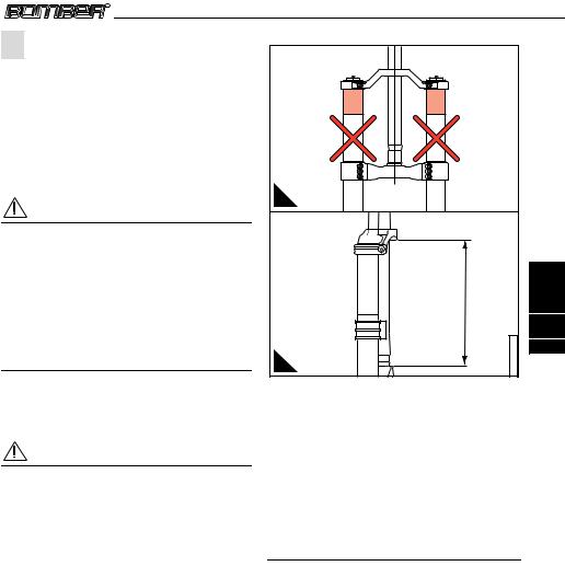
On all dual crown MY 2005 BOMBER models, the lower crown is clamped to the stanchions (or to the sliders in the upsidedown models) through some bolts. In this case, you will have to respect following precautions during installing:
•In case of oversized diameter areas on the stanchions or on the sliders, the crowns clamping can only be done in the shaded area shown in Picture 2A.
•In case of reference notches on the stanchions or on the sliders, the lower part of the lower crown must be positioned over the notch.
•The distance between the inflated tire and the lower part of the lower crown, keeping the fork at travel’s end, must be at least 4 mm.
MZ024
Installation
A
H |
English |
|
MZ024002 |
3 |
|
103 |
|
B |
|
Picture 2 - Dual crown forks installation on the frame: (2A) Crowns fastening, (2B) Steer tube maximum length between crowns
•Ne the Monster forks the distance between the lower part of the lower crown and the dust seal, keeping the fork at travel’s end, must be at least 4 mm.
•On the dual crown forks the maximum length of the steer tube between the two crowns (see Picture 2B) must be smaller than the values (H) shown in the Tab.3.1
Table 3.1: Steer tube maximum length between crowns
|
Steer tube max. |
|
Fork |
length between |
|
|
crowns |
|
888 Series |
164 mm |
|
888 Series (with high upper |
184 mm |
|
crown) |
||
|
||
Junior T |
184 mm |
|
Shiver DC (with standard |
145 mm |
|
upper crown) |
||
|
||
Shiver DC (with high upper |
163 mm |
|
crown) |
||
|
||
Monster T |
190 mm |
English
3
104
Installation
3.2 Installing the brake system
Picture 3
Installing the brake system is a very delicate operation that must be carried out by specialized personnel.
WARNING!
Brake system installation requires specialized knowledge, tools and experience. General mechanical aptitude may not be sufficient to properly install your brake system. Please have your brake system installed only by an authorized Marzocchi Service Center. In particular, improper installation of a disk brake system can overstress the caliper mountings, which
Table 3.1: Brake system settings
may cause the calliper mountings to break, resulting in loss of control of the bicycle, an accident, personal injury or death.
Be sure that the brake system installation is also performed in strict compliance with the instructions provided by the brake system manufacturer.
Use only brake systems that comply with the fork’s specifications, taking into consideration the contents of the summarizing tables contained in this manual.
|
Fork |
|
|
V-brake setting |
Disk maximum |
|
|
|
|
dimensions |
|||
|
|
|
|
|
|
|
Marathon (except Marathon |
V-brake removable setting |
XC INTL STD 6" |
||||
|
Race) |
- |
MX |
|
||
|
|
|
|
|||
|
Marathon Race |
|
V-brake fixed setting |
XC INTL STD 6" |
||
66 |
- 888 - |
All Mountain |
- |
|
|
|
Dirt Jumper |
- Shiver SC |
- |
/ |
XC INTL STD 8" # |
||
Shiver DC - Z1 FR |
- Junior T |
|
|
|||
|
D-Street |
|
V-brake removable setting |
XC INTL STD 8" # |
||
|
Monster T |
|
/ |
8" Post Mount |
||
|
|
|
|
|
|
|
# |
The 8" disk installation is allowed with the specific adapter, that must be provided by the brake |
|||||
|
|
|
|
|
system manufacturer. |
|
3A |
3B |
MZ024003 |
3C |
|
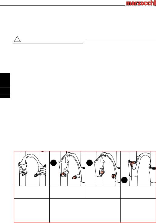
V-Brake system Fixed |
V-Brake system |
Disk brake system sheath |
Disk brake system sheath |
setting |
Removable setting |
mountings |
mountings |
Marathon Race |
D-Street 24" |
66 Series |
|
|
MX Series |
888 Series |
|
|
Marathon Series (escluso Marathon Race) |
All Mountain Series |
|
|
|
|
D-Street 24" |
|
|
|
Dirt Jumper Series |
|
|
|
Z1 FR Series |
Picture 3 - Braking system settings |
|
|
|
MZ024
Installation
WARNING!
Don’t forget that a special thread-lock treatment is applied to the bolts thread (3A) ; bolts which are installed and then removed lose this treatment and therefore may never be used again.
Make sure before every ride that the brake cable of the disk brake system is correctly connected to the proper mounting (3B,3C).
3.3 Wheel Installation
Table 3.1: Maximum wheel dimension
WARNING!
The brake cable shall never touch the crown and stanchions.
|
|
Fork |
|
Maximum wheel |
|
|
|
dimension |
|
|
|
|
|
|
D-Street |
|
|
|
2,5” x 24" |
All Mountain |
- Dirt Jumper - Z1 FR - Shiver SC |
- Shiver |
2,8” x 26" |
|
DC - Junior T |
|
|||
|
|
|||
Marathon |
- |
MX |
|
2,2” x 26" |
66 - 888 |
- |
Monster T |
|
3,0” x 26" |
In case you need to install wheels having bigger dimensions, you will have to verify that:
•The tire turns freely, there is no contact with the brake arch or the V-Brake system
•The distance between the inflated tire and the lower part of the lower crown, keeping the fork’s legs fully compressed, must be at least 4 mm.
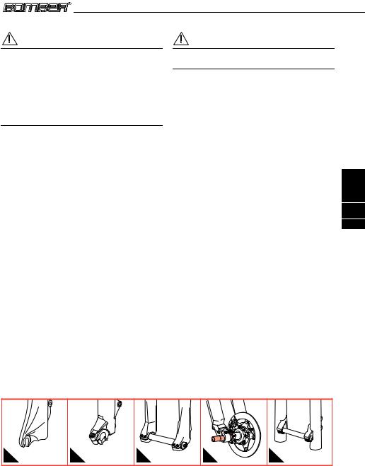
3.4 Wheel axle securing system
Picture 4
The system for securing the wheel axle to the fork sliders can be standard, with traditional advanced dropouts or with ø 20 mm through hole axle.
Foks that are created for more intensive use are provided with a wheel fastening system originating from the motocross application, using a 20 mm axle.
English
3
105
A |
B |
C |
D |
E |
MZ024004
Picture 4 - Wheel securing systems: (4A) standard dropouts, (4B) ø 20 mm through hole axle (forks with ø32 mm stanchions), (4C) ø 20 mm through hole axle (66 series and 888 series forks), (4D) ø 20 mm through hole axle (Shiver series), (4E) ø 20 mm through hole axle (Monster T).
MZ024

English
3
106
Installation
3.4.1 Wheel installation on a standard fork’s end
Install the wheel in compliance with the manufacturer’s instructions.
For correct fork function after installing the wheel you will need to:
•Check fork-wheel alignment by fully compressing the fork a few times. The wheel should not make contact with or come close to any portion of the fork.
•Lift the front of the bicycle, and spin the wheel a few times to verify correct alignment and spacing with the disk brake or the V-Brake brake pads. Check the owner’s manual for the brake system for the proper specifications.
3.4.2Wheel installation on ø 32 mm forks with ø 20 mm through hole
axle
Picture 5
For correct fork function, please follow the instructions here below when installing the wheel:
•Insert the axle (5A) through the right fork wheel axle clamp, the wheel and the left fork wheel axle clamp.
•Tighten the axle acting on the cap (5B), using a 6 mm Allen key to the required tightening torque (15±1 Nm).
•Check the correct fork-wheel alignment, by fully compressing the fork a few times. The wheel should not make contact with or come close to any portion of the fork. Lift the front of the bicycle and spin the wheel a few times to verify the correct alignment with the disk brake. Check the owners manual for the brake system for the proper specifications.
•Tighten the screws (5C) positioned on both wheel axle clamps, using a 4 mm (5 mm for D-Street 24”) Allen key to the required torque (6±1 Nm (10±1 Nm for D-Street 24”).
5A |
6 mm
15±1 Nm
5B |
4 mm |
D-Street 24" |
|
5 mm |
6±1 Nm |
10±1 Nm |
5C |
MZ024005

Picture 5 - Wheel installation on ø 32 mm forks with ø 20 mm through hole axle
MZ024
|
|
|
Installation |
|
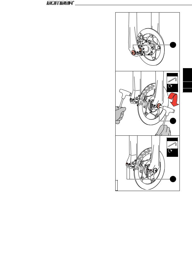
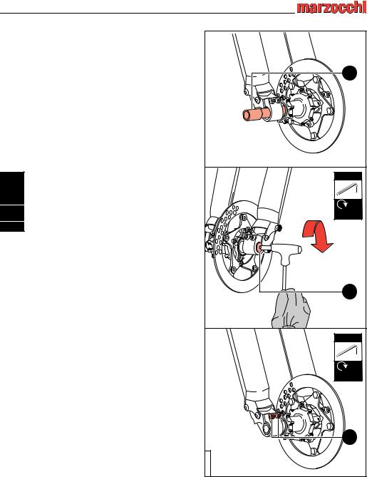
3.4.3 Wheel installation on 66 and 888 |
|
|
||
|
series forks |
|
|
|
Picture 6 |
|
|
|
|
For correct fork function, please follow the |
|
|
||
instructions here below |
when installing the |
|
|
|
wheel: |
|
|
|
|
• Insert the axle (6A) |
through the right fork |
6A |
|
|
|
wheel axle clamp, the wheel and the left fork |
|
||
|
wheel axle clamp. |
|
|
|
• Tighten the axle acting on the cap (6B), using |
|
|
||
|
a 6 mm Allen key to the required tightening |
|
|
|
|
torque (15±1 Nm). |
|
|
|
• |
Check the correct fork-wheel alignment, by |
|
English |
|
|
fully compressing the fork a few times. The |
6 mm |
||
|
|
|||
|
wheel should not make contact with or come |
|
||
|
close to any portion of the fork. Lift the front |
|
|
|
|
of the bicycle and spin the wheel a few times |
|
3 |
|
|
to verify the correct alignment with the disk |
|
||
|
15±1 Nm |
107 |
||
|
brake. Check the owners manual for the |
|||
|
brake system for the proper specifications. |
|
|
|
• |
Tighten the screws (6C) positioned on both |
|
|
|
|
wheel axle clamps, using a 4 mm Allen key to |
|
|
|
|
the required torque (6±1 Nm), with the |
|
|
|
|
sequence 1-2-1. |
|
|
|
|
|
|
6B |
|
|
|
|
4 mm |
|
|
|
|
6±1 Nm |
|
|
|
|
6C |
|
|
|
|
MZ024006 |
|
|
|
|
Picture 6 - Wheel installation on 66 and 888 series |
|
|
|
|
forks |
|
MZ024
English
3
108
Installation
3.4.4 Wheel installation on Shiver series forks
Picture 7
For correct fork function, please follow the instructions here below when installing the wheel:
•Insert the wheel axle (7A) through the right wheel axle clamp, the wheel and the left wheel axle clamp.
•Using a 6 mm Allen key, screw down the bolt (7B) on the left side and tighten to the required torque (15±1 Nm).
•Check the correct fork-wheel alignment, by fully compressing the fork a few times. The wheel should not make contact with or come close to any portion of the fork. Lift the front of the bicycle and spin the wheel a few times to verify the correct alignment with the disk brake. Check the owners manual for the brake system for the proper specifications.
•Tighten the screws (7C) positioned on both wheel axle clamps, using a 5 mm Allen key to the required torque (10±1 Nm), with the sequence 1-2-1.
7A |
6 mm |
15±1 Nm |
7B |
5 mm |
10±1 Nm |
7C |
MZ024007 |
Picture 7 - Wheel installation on Shiver series forks
MZ024