

2005-bomber-en
.pdf
|
|
|
|
Installation |
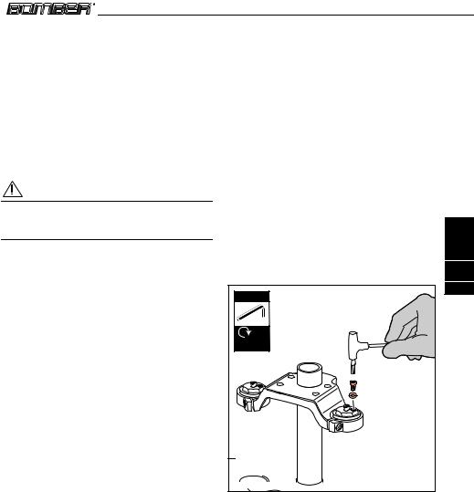
3.4.5 Wheel installation on Monster |
|
|
4 mm |
|
|
series forks |
|
|
|
|
|
|
|
|
Picture 8 |
|
|
|
|
For a correct fork’s function, please follow the |
|
|
|
|
instructions here below when installing the |
|
|
8B |
|
wheel. |
|
|
|
|
• |
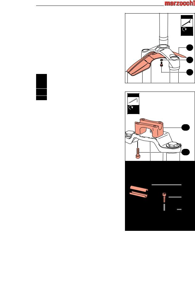
In case the fork has been disassembled from |
|
8A |
8A |
|
the bike frame or the fork’s legs position as to |
|
|
|
|
the crowns has been changed, you will have |
|
|
|
|
to slightly loose the 6 bolts (8A) holding the |
|
|
|
|
arch (8B) by means of a 4 mm Allen key. |
|
|
8C |
• |
Insert the wheel axle (8C) through the right |
|
|
|
|
|
|
||
|
wheel axle clamp, the wheel and the left |
|
|
|
|
wheel axle clamp. |
|
|
English |
• |
By using a 6 mm Allen key tighten the axle |
|
|
|
|
|
|
||
|
bolt (8D) located on the left side to the |
|
|
|
|
required torque (15±1 Nm). |
|
|
6 mm |
• |
Check the correct fork-wheel alignment, by |
|
|
3 |
|
fully compressing the fork a few times. The |
|
|
109 |
|
wheel should not make contact with or come |
|
|
|
|
|
|
|
|
|
close to any portion of the fork. Lift the front |
|
|
15±1 Nm |
|
of the bicycle and spin the wheel a few times |
|
|
|
|
to verify the correct alignment with the disk |
|
|
|
|
brake. Check the owners manual for the |
|
|
|
|
brake system for the proper specifications. |
|
8D |
|
• |
Tighten the screws (8E) positioned on both |
|
|
|
|
|
|
||
|
wheel axle clamps, using a 5 mm Allen key to |
|
|
5 mm |
|
the required torque (10±1 Nm), with the |
|
|
|
|
sequence 1-2-1. |
|
|
|
• By using the 4 mm Allen key tighten the bolts |
|
|
|
|
|
(8A) with the sequence 1-2-3-2-1 to the |
|
|
10±1 Nm |
|
required torque (6±1Nm). |
|
|
|
|
|
|
|
|
|
|
|
|
8E |
|
|
|
|
4 mm |
|
|
MZ024008 |
|
6±1 Nm |
|
|
8A |
8A |
|
|
|
|
||
|
|
Picture 8 - Wheel installation on Monster series forks |
||
MZ024
Installation
English
3
110
3.5 Fender Installing
Picture 9
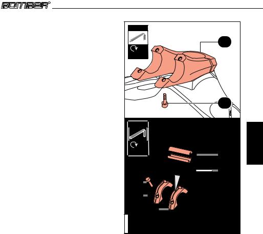
A fender may be installed on the 66, 888, All Mountain, Junior T, Z1 FR models. The fender can be provided with the fork or purchased separately.
When assembling the fender (9A) you must insert the small support bushing (9B) between the screw and the fender as shown in the picture, and tighten the screws (9C) with a 8 mm Allen wrench to the required torque (6±1Nm).
|
8 mm |
|
6±1 Nm |
|
9A |
|
9B |
MZ024009 |
9C |
|
|
|
|
|
|
|
Picture 9 - Fender Installing |
|
|
3.6 |
Handlebar clamp installing |
5 mm |
|
|||||
|
|
|
|
|
|
|
||
The dual crown models can be provided with |
|
|||||||
handlebar clamp (the handlebar clamp may be |
|
|||||||
sold together with the fork or purchased |
|
|||||||
separately). |
|
|
|
10±1 Nm |
|
|||
|
|
|
|
|
|
|
||
3.6.1 Handlebar clamp installing on all |
|
|||||||
|
dual crown models except the 888 |
10A |
||||||
|
series |
|
|
|
|
|||
|
|
|
|
|
|
|||
Picture 10 |
|
|
|
|
|
|
||
For the installation please carefully follow these |
|
|||||||
instructions: |
|
|
|
|
|
|||
• Install the handlebar |
lower mounting (10A) |
|
||||||
on the upper crown, in a way that the holes |
10B |
|||||||
coincide. |
|
|
|
|
|
|
||
• Fix the handlebar clamp by tightening the |
|
|||||||
screws |
(10B) |
to |
the |
required |
torque |
|
||
(10±1Nm), using a 5 mm Allen key. |
|
|
||||||
• Install the handlebar in the mounting in a |
|
|||||||
central position. |
|
|
|
|
|
|||
• Lock the handlebar with the appropriate |
10E |
|||||||
clamp (10C). |
|
|
|
|
|
|||
• Tighten |
the screws |
(10D) |
to the |
required |
10D |
|||
torque (10±1 Nm), using a 5 mm Allen key. |
||||||||
|
||||||||
You can find reduction shells (10E) as a spare |
10C |
|||||||
part if needed, to allow installation of handlebars |
|
|||||||
having different diameter. |
|
MZ025013 |
|
|||||
|
|
|
|
|
|
MZ024 |
||
|
|
|
|
|
|
Picture 10 - Handelbar clamp installing |
|
|
|
|
Installation |
|
3.6.2 Handlebar clamp installing on 888 |
4 mm |
|
|
series |
|
|
|
|
|
|
|
Picture 11 |
|
11A |
|
For the installation please carefully follow these |
|
|
|
instructions: |
6±1 Nm |
|
|
|
|
|
|
• Install the handlebar lower mounting (11A) on |
|
|
|
the upper crown, in a way that the holes |
|
|
|
coincide. |
|
|
|
• Fix the handlebar clamp by tightening the |
|
|
|
screws (11B) to the required torque (6±1Nm), |
|
|
|
using a 4 mm Allen key. |
|
11B |
|
• Install the handlebar in the mounting in a |
|
|
|
|
|
|
|
central position. |
|
|
|
• Lock the handlebar with the appropriate |
4 mm |
|
English |
clamp (11C). |
|
|
|
|
|
|
|
• Tighten the screws (11D) to the required |
|
|
|
torque (6±1 Nm), using a 4 mm Allen key. |
6±1 Nm |
11E |
3 |
|
|||
|
|
||
You can find reduction shells (11E) as a spare |
|
|
111 |
|
11D |
|
|
part if needed, to allow installation of handlebars |
|
|
|
having different diameter. |
11D |
|
|
|
|
|
|
|
11C |
|
|
|
11C |
|
|
|
MZ024011 |
|
|
|
Picture 11 - Handlebar clamp installingon 888 series |
|
|
|
|
forks |
|
MZ024
Maintenance
446 MAINTENANCE
4.1 Problems - Diagnosis - Solutions
This paragraph indicates some of the problems that may arise during the fork’s use, as well as the possible causes of these problems and the suggested solutions.
Always check this table before working on the fork.
English
4
112
WARNING!
The operations listed below accompanied by this symbol  must be performed only by MARZOCCHI authorized centres.
Table 4.1: Problems - Diagnosis - Solutions
Problem |
Diagnosis |
|
|
Solution |
|
|
|
|
Increase spring preload |
|
|
|
|
Add spring preload by replacing |
|
|
|
|
|
Fork has too much sag |
Spring rate too soft or fork |
|
|
the preload tube |
|
|
|||
|
|
Check the oil level |
||
|
|
|||
oil too fluid |
|
|
||
|
|
|
|
|
|
|
|
|
Change to stiffer spring rate |
|
|
|
|
|
|
|
|
|
|
|
|
|
|
Increase air pressure |
|
|
|
|
Increase compression damping |
Forks bottoms too easily, but it |
Not enough compression |
|
|
by changing oil level |
|
|
|||
has the recommended sag |
damping |
|
|
Increase compression damping |
|
|
|
|
through the proper adjuster |
Fork bottoms too easily; |
|
|
|
Check oil level |
|
|
|
||
Spring rate too soft or fork |
|
|
|
|
needs more than maximum |
|
|
Install stiffer springs |
|
oil too fluid |
|
|
||
preload |
|
|
||
|
|
|
|
|
|
|
|
|
Increase air pressure |
|
|
|
|
Check oil level |
|
Spring rate too stiff or fork |
|
|
|
Fork does not get full travel |
|
|
Install softer spring |
|
oil level too high |
|
|
||
|
|
|
|
|
|
|
|
|
|
|
|
|
|
Decrease air pressure |
Fork extends too quickly; |
Not enough rebound |
|
|
Increase rebound damping |
|
|
Replace oil (SAE 7,5) with a |
||
harsh top-out after impacts |
damping |
|
|
|
|
|
higher viscosity |
||
|
|
|
|
|
|
|
|
|
|
|
Not enough compression |
|
|
Increase compression damping |
Fork bottoms out too quickly |
|
|
at the travel end via the proper |
|
damping |
|
|
||
|
|
|
adjuster |
|
|
|
|
|
|
Front wheel wants to tuck |
Too much rebound |
|
|
Decrease the rebound damping |
damping; spring rate too |
|
|
|
|
under while cornering |
|
|
Increase spring rate |
|
soft |
|
|
||
|
|
|
|
|
MZ024
|
|
|
|
|
|
|
|
|
|
|
|
|
Maintenance |
|
|
|
|
|
|
|
|
|
|
|
|
|
|
|
|
|
|
Problem |
|
|
Diagnosis |
|
|
|
|
Solution |
||||
|
|
Fork “packs up” or stays down |
|
|
|
|
|
|
|
|
|
|||
|
|
in travel during multiple |
Too much rebound damping |
|
|
|
Decrease rebound damping |
|||||||
|
|
impacts |
|
|
|
|
|
|
|
|
|
|||
|
|
Knocking sound during |
Too much rebound damping |
|
|
|
|
Decrease rebound damping |
||||||
|
|
rebound, but no harsh top-out |
|
|
|
|
||||||||
|
|
Oil “ring” on stanchions |
Oil seals are contaminated |
|
|
|
|
Replace all seals |
||||||
|
|
|
|
|
|
|
|
|
|
|
|
|
|
|
|
|
Heavy amount of oil on |
|
|
Seals are damaged, |
|
|
|
Replace all seals and have the |
|||||
|
|
stanchions; oil dripping down |
|
|
stanchions could be |
|
|
|
||||||
|
|
|
|
|
|
|
|
stanchions inspected |
||||||
|
|
legs |
|
|
damaged |
|
|
|
|
|||||
|
|
|
|
|
|
|
|
|
|
|||||
|
|
Fork is sticky; fork does not |
Oil seals are contaminated; |
|
|
|
|
Replace all seals |
||||||
|
|
perform as new |
fork needs to be serviced |
|
|
|
|
|||||||
|
|
|
|
|
|
|
|
|
|
|
|
|
|
|
|
|
Oil leakage from the bottom |
Loose bottom nut/screw |
|
|
|
|
Tighten bottom nut/screw |
||||||
|
|
|
|
O-ring damaged |
|
|
|
|
Replace O-ring |
|||||
|
|
|
|
|
|
|
|
|||||||
|
|
|
|
|
|
|
|
|
|
|
|
|||
|
|
|
|
|
|
|
|
|
|
|
|
|
|
|
|
|
Loss of sensitivity |
|
|
Worn sliding bushings |
|
|
|
|
Replace sliding bushings |
||||
|
|
|
|
|
|
|
|
|
|
|
||||
|
|
|
|
|
|
|
|
Old oil |
|
|
|
|
Change oil |
|
|
|
|
|
|
|
|
|
|
|
|
|
|
|
|
|
|
Unusual soundscoming from |
|
|
|
|
|
|
|
|
|
|||
|
|
the TAS cartridge |
TAS cartridge is damaged |
|
|
|
Contact a service center to verify |
|||||||
|
|
|
|
|
||||||||||
|
|
The TAS control knob turns |
|
|
|
|
the correct fork’s function |
|||||||
|
|
|
|
|
|
|
|
|
||||||
|
|
during use |
|
|
|
|
|
|
|
|
|
|||
|
|
WARNING! |
|
|
|
|
|
|
|
|
|
|||
|
The operations listed below accompanied by this symbol |
|
|
|
must be performed only by |
|||||||||
|
|
|
|
|||||||||||
|
MARZOCCHI authorized centres. |
|
|
|
|
|
||||||||
|
Table 4.2: Periodic maintenance table |
|
|
|
|
|
||||||||
|
|
|
|
|
|
|
|
|
|
|
|
|
|
|
|
|
General maintenance |
|
|
|
|
Use |
|
||||||
|
|
operation |
|
|
Intense |
|
|
|
Normal |
|
||||
|
|
Check that screws are |
|
|
|
|
Before every ride |
|
||||||
|
|
tightened to required torque |
|
|
|
|
|
|||||||
|
|
|
|
|
|
|
|
|
|
|
|
|
||
|
|
Stanchions cleaning |
|
|
|
|
After every ride |
|
||||||
|
|
Air pressure control |
|
|
|
|
Before every ride |
|
|
|
10 hours |
|
||
|
|
Air bleed (Monster T) |
|
|
|
|
Before every ride |
|
|
|
10 hours |
|
||
|
|
Oil seals control |
|
|
|
|
25 hours |
|
|
|
50 hours |
|
||
|
|
|
|
|
|
|
|
|
|
|||||
|
|
|
|
|
|
|
|
|
|
|
|
|
|
|
|
|
Fork oil change |
|
|
|
50 hours |
|
|
|
100 hours |
|
|||
|
|
|
|
|
|
|
|
|
|
|
|
|
|
|
|
|
TST Cartridge oil change |
|
|
|
|
25 hours |
|
|
|
50 hours |
|
||
|
|
|
|
|
|
|
|
|
|
|||||
|
|
|
|
|
|
|
|
|
|
|
|
|
|
|
|
|
Fork’s oil seals replacement |
|
|
|
|
|
|
|
|
|
|
|
|
|
|
/ TST Cartridge / DOPPIO |
|
|
|
50 hours |
|
|
|
100 hours |
|
|||
MZ024 |
|
AIR Cartridge |
|
|
|
|
|
|
|
|
|
|
||
|
|
|
|
|
|
|
|
|
|
|
|
|
|
|
English
4
113

English
4
114
Maintenance
4.2General maintenance recommendations
•After disassembling the forks, always use new, original Marzocchi seals when reassembling.
•To tighten two bolts or nuts that are near each other, always follow the sequence 1-2-1, and tighten to the required tightening torque (see
Table 6.14 - Tightening torques).
•Never use flammable or corrosive solvents to clean the parts, as these could damage the seals. If you must use a solvent, use biodegradable detergents that are not corrosive, not flammable or have a high flash point
•If you are planning not to use your fork for a long period of time, always lubricate the fork’s components that are in contact with the fork’s oil.
•Never pour lubricants, solvents or detergents which are not completely biodegradable in the environment; these must be collected and kept in the appropriate containers, then disposed of according to local laws.
•All of the components of Marzocchi forks are metric. Use only metric tools, imperial (US) tools may have similar sizes, but can damage the bolts and make it impossible to unscrew them.
•Use the correct size and sort of screwdriver to unscrew slotted or crosshead (Phillips) screws.
•When using a screwdriver to assemble or disassemble metal stop rings, o-rings, sliding bushings or seal segments, avoid scratching or cutting the components with the screwdriver tip.
•Do not carry out any maintenance and / or adjustment operations that are not explained in this manual.
•If you have any questions regarding the care, maintenance or use of your suspension system, please contact your nearest Marzocchi service center directly. A list of service centers can be found at the end of this manual or on the Internet page www.marzocchi.com.
•This manual does not explain how to assemble/disassemble the fork from the bicycle, the wheel, the steering set or any other component directly or indirectly associated with the fork that are not actually a part of the fork. MARZOCCHI reserves the right, in its sole discretion, to make changes to the products, at any time and without prior notice.
•Only use original Marzocchi spare parts.
•Work in a clean, ordered and well-lit place; if possible, avoid servicing your fork outdoors.
•Polished surfaces need to be periodically treated with some “polishing compound” to be kept as bright as new.
•Carefully check there are no metal shavings or dust in the work area.
•Never modify in any way any component of your fork.
MZ024
Maintenance
4.3 Cleaning the fork legs
The manufacturer lubricates the fork dust seal with some grease, which makes the stanchion tubes slide easier, especially when the fork has not been used for a long time.
When using the fork, such grease can melt and stick to the stanchions, looking like an oil leak, although it is not.
After every use carefully clean the fork’s outside surfaces, with a special attention to stanchion tubes and dust seals.
WARNING!
Mud and dust may cause serious damages to the suspension system if not immediately removed.
4.4 Monster T air bleeding
Picture 12
This operation must be carried out with the fork assembled on the bicycle and with the fork’s legs fully extended (front wheel off the ground)
The pressure generated by the air that can get into the fork legs while the bike is being used and which, due to the special shape of the oil seals remains trapped inside, can cause the fork to malfunction.
•In case of malfunction or loss of legs’ smoothness please carry out following operation on both legs:
•By means of a 2 mm Allen key, unscrew the air bleed screw (A) located on the cap, in order to drain the pressure generated inside the fork’s leg.
•Check the oil seal (B) condition; replace if needed.
•Tighten the air bleed screw (A) to the recommended torque (2±0,5 Nm), being careful not to damage the oil seal (B).
English
4
115
2 mm
2±0,5 Nm
MZ024012

Picture 12 - Monster T air bleeding
MZ024
English
5
116
Adjustments
556 ADJUSTMENTS
With a correct setting you may obtain the maximum performance from the suspension system. In this paragraph you will find how to carry out a correct setting of Marzocchi forks.
In order to find the best setting you will need to try several times to understand where and how to intervene.
The best setting depends on the mountain bike frame geometry, the rider’s weight, the trail and obstacles kind, but also on many other personal factors connected with the riding style; it is therefore not possible to provide you with objective information concerning the desired setting.
However, if you carefully follow the instruction here below, you may find the best setting in a short time.
The fork setting must be done by acting on only one adjuster at a time, taking note of the modifications you carry out and the improvements you obtain.
WARNING!
During the setting operations never force the adjusters past their limits and do not exceed the recommended maximum air pressure.
WARNING!
To keep the pressure inside the fork’s legs only use the special MARZOCCHI pump with gauge, that you can buy at the authorized centers.
WARNING!
The use of any other pump can compromise the inflating operation and cause malfunction or damages to the fork.
5.1 Adjustment kit and springs
For information concerning travel increase kits, adjustment kits and springs having different hardness (K) please visit our web page: www.marzocchi.com.
5.2 Spring preload
The best spring preload is the one allowing you to obtain the desired SAG point due to the rider’s weight (SAG) (see par. SAG page 117).
The preload spring may be adjusted according to the different models, through mechanical adjusters or with pressurized air inside the fork’s leg.
On the models provided with mechanical adjustment each adjuster turn corresponds to a 1mmspring compression.
WARNING!
The forks provided with preload mechanical adjustment are set to the minimum preload by the manufacturer, i.e. the adjuster knob is completely turned counterclockwise. However, the spring is slightly preloaded to help counteract static load.
5.3 Positive Air
The positive air is the elastic factor for air forks. The best positive air pressure allows you to obtain the desired SAG (see par. SAG page 117).
NOTE
Once you have found the best setting, we suggest taking note of the adjuster clicks or the number of turns, as to the “all closed” position (adjuster completely turned clockwise), so that it will be easier to re-establish the original setting after possible changes.
MZ024
Adjustments
SAG
The SAG corresponds to the fork’s sinking due to the rider’s weight.
How to measure it
Picture 13
In order to measure the SAG you only need to carry out following steps:
Measure the fork’s leg portion between the lower crown and the dust seal and take note of the value (A).
Repeat the measurement sitting on the bike and take note of the value (B).
A |
B |
MZ024013 |
Picture 13 - How to measure SAG
SAG= A - B
How to find the best SAG
The best sag corresponds to 15 -20% for Cross-country forks and to 25 - 30% for Freeride forks.
In order to calculate the best SAG for your own fork, you will only need to do following calculation:
SAG = T x S (T = total travel; S = suggested sinking percentage).
English
5
117
MZ024

English
5
118
Adjustments
5.4 Negative air
If you inflate pressurized air through the valve, you can reduce the fork’s static load.
By increasing the pressure inside the fork’s leg, you increase the force helping the fork to start sliding.
Moreover, the negative air allows regulating the travel maximum value in a range corresponding to 20 mm.
If you increase the pressure inside the fork’s leg, you reduce the travel.
5.5PAR – Air progression at travel end
If you inflate pressurized air through the valve, you can modify the damping of the forces generated during the compression phase at the fork’s legs travel end.
If you increase the pressure inside the fork’s leg, you increase the compression final braking.
5.6 Rebound adjustment
Through the extension adjuster you can control the fork’s rebound speed following to compression.
A correct adjustment of the rebound speed allows you to have a stable bike whose wheel can perfectly deal with any obstacle.
If the adjustment is too reactive, the forecarriage becomes unstable and the mountain bike may swing. On the contrary, a too slow adjustment makes the overcoming of multiple obstacles difficult, where the suspension cannot go back to a complete extended position between an obstacle and the following one.
The rebound speed adjustment is made through internal or external adjusters.
5.7 Compression adjustment
You can control the compression speed through the compression adjuster.
The compression adjustment can be done according to the user’s needs and it must prevent the fork’s bottoming.
A “hard” compression adjustment offers more stability and allows a more aggressive riding style, making the mountain bike more reactive, while a “softer” adjustment offers less stability with the advantage of a less “nervous” riding style.
The compression adjustments, according to the models, can control the compression damping on the whole travel or they can progressively intervene at the end of travel only.
5.8 ETA (Extension Travel Adjust)
The ETA cartridge offers “on-the-fly” adjustment of the rebound damping, by reducing the fork’s length, but still keeping 30 mm of travel.
The adjustment has two positions:
Position LOCK
When turning the knob clockwise, you activate the ETA cartridge function.
In this position the fork’s legs will stay down after impacts; additional impacts will further lower the fork.
This position is only suitable for hard, steep climbs.
Position UNLOCK
When turning the knob counterclockwise, you reset the fork’s normal function by deactivating the ETA cartridge function.
WARNING!
NEVER use the LOCK position while riding downhill as the fork will not react appropriately when hitting obstacles, resulting in loss of control of the bicycle, an accident, personal injury or death.
MZ024