

Broadband Packet Switching Technologies
.pdfTHE 3M SWITCH |
299 |
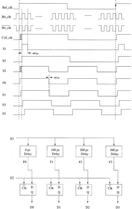
Fig. 11.17 Block diagram of the timing signal generator.
line fabrication, such as polarization, noise reduction, coherent crosstalk, and power stabilization. InP-based semiconductor Y-junction switches have been implemented for the delay units.
The cell clock generated in the cell delineation unit indicates the cell boundaries. By comparing the cell clock with a reference clock generated by the system, a 9-bit digitized timing difference can be obtained by using a 9-bit counter in the coarse adjustment circuit. Signals C1 to C9 control the nine switching stages Žeach consisting of two SOA gates. to determine if each cell should pass the fiber delay line or not. As shown in Figure 11.17, three important timing signals S1 to S3 are generated by the timing signal generator. S1, shown in Figure 11.18, is used to enable the 9-bit counter at the beginning of the Cell clk. As the 9-bit counter is incremented by the bit clock, its output is sampled and latched at the next rising edge of the Ref clk. Thus, the latch value ŽC1 to C9. indicates the phase difference between the Cell clk and the Ref clk at bit level.
However, to identify the timing difference for less than one bit is challenging. A novel sampling technique is adopted to adjust the phase down to 100 ps without using a 10-GHz clock. The signal S2, a variant Cell clk that is aligned with the bit clock as shown in Figure 11.18, is used as a sample clock to determine the phase difference between the Cell clk and the Ref clk at the sub-bit level. The signal S3 mimics the Cell clk but with a shorter duration and is used to produce four similar signals ŽF0 to F3., each separated by 100 ps. The signal S2 then samples the signals F0 to F3 as shown in the fine delay comparator ŽFig. 11.19.. The sampled outputs D0 to D3 show the phase difference within a bit. For instance, the sampled value in Figure 11.18 is 1100, corresponding to a phase difference of 100 ps. Note that the actual phase difference can be anywhere between 100 and 200 ps. Since the resolution is 100 ps, the phase adjustment error is limited to 100 ps.
300 OPTICAL PACKET SWITCHES
Fig. 11.18 Sample timing of the fine adjustment circuit Ž 14 bit..
Fig. 11.19 Fine delay comparator.
|
OPTICAL INTERCONNECTION NETWORK FOR TERABIT IP ROUTERS |
301 |
|||||
TABLE 11.1 Conversion Table Between [D0, D1, D2, D3] and [C10, C11] |
|
|
|||||
|
|
|
|
|
|
|
|
D0 Ž0 ps. |
D1 Ž100 ps. |
D2 Ž200 ps. |
D3 Ž300 ps. |
C10 |
C11 |
||
|
|
|
|
|
|
|
|
0 |
0 |
0 |
0 |
0 |
|
0 |
|
1 |
0 |
0 |
0 |
0 |
|
0 |
|
1 |
1 |
0 |
0 |
0 |
|
1 |
|
1 |
1 |
1 |
0 |
1 |
|
0 |
|
1 |
1 |
1 |
1 |
1 |
|
1 |
|
|
|
|
|
|
|
|
|
Table 11.1 shows the mapping of the fine sampled value ŽD0 to D3. to the last two bits of the delay line control ŽC10, C11..
With different combinations of C1 to C11, the optical delay elements are tuned to insert the desired delay needed to align the phase of incoming cells. For example, with wC1, C2, . . . , C11x s w1, 0, 1, 0, 0, 0, 0, 0, 0, 0, 1x, a total delay of Tr2 q Tr23 q Tr211 Žthe last term is 14 bit. is added by the cell synchronization unit.
11.4 OPTICAL INTERCONNECTION NETWORK FOR TERABIT IP ROUTERS
11.4.1Introduction
The tremendous increase in the speed of data transport on optical fibers has stimulated a large demand for gigabit multimedia services such as distance learning and video conferencing. The Internet, capable of supporting various information transport with the robust and reliable Internet protocol ŽIP., is widely considered as the most reachable platform of next-generation information infrastructure w33x. The key to the success of next-generation Internet ŽNGI. lies in the deployment of terabit IP routers to meet the exponential growth of multimedia traffic.
Although several large-capacity routers have been proposed w34, 35, 36, 37, 38, 39, 40, 41, 42, 43x, building an IP router with multiterabit- per-second capacity still remains to be seen. The challenges of building a terabit IP router include: Ž1. implementing a large-capacity switch fabric providing high-speed interconnection for a number of smaller-capacity routing modules ŽRMs., and Ž2. devising a fast arbitration scheme resolving output contention within stringent time constraint while achieving high throughput and low delay.
By combining the strength of both optical and electronic technologies, a terabit packet switch architecture is proposed to use a nonblocking bufferless optical interconnection network ŽOIN. to interconnect multiple electronic RMs. The reason that an OIN is used rather than an electronic interconnection network ŽEIN. is to reduce the number of interconnection wires and to eliminate the problem of electrical magnetic interference in the EIN. The
302 OPTICAL PACKET SWITCHES
OIN takes advantage of the WDM technology by carrying multiple packets on different wavelengths and thus providing a large bandwidth for each interconnection fiber. As a result, the total number of interconnection wires is dramatically reduced.
The OIN uses a hierarchical broadcast-and-select approach to interconnect a number of optical transmitters and receivers. As the dense WDM technology matures, multiplexing 100 wavelengths in the 1550-nm window and amplifying them simultaneously become feasible w7x. In addition, the advance of the optical hybrid integration of planar lightwave circuits ŽPLCs. and semiconductor devices makes an optical system more cost-effective w44, 45, 46x. Thus, the OIN based on WDM and optical hybrid integration techniques will play an important role in providing terabit-per second switching capacity. One of its challenges is to synchronize optical data signals and electronic control signals. A couple of bits may be used as a guard time to circumvent the slower switching speed of optical devices. An adjustable electronic delay circuit can always be added to the control signals so that they can be tuned to align with the optical data signals.
In order to meet the stringent time constraint imposed on IP forwarding, especially IP table lookup, the operation of IP forwarding is separated from the construction of routing tables and the execution of routing protocols. IP forwarding is implemented in hardware at each RM, while the construction of routing tables and the execution of routing protocols is handled by the route controller ŽRC.. Currently an Internet backbone router can have more than 40,000 routes in its routing table w47x. As the number of routes is still increasing, computing and maintaining the routing tables by the RC becomes more and more challenging. One solution could be using multiple RCs and interconnecting them to achieve both higher processing speed and load balancing. The RMs and the RCs can be interconnected either using dedicated buses, such as the peripheral component interconnect ŽPCI. bus, or through a core switch fabric, such as the OIN.
Input and output buffering together with internal speedup is used to achieve high switch performance and low loss rate at a reasonable complexity. Purely input buffering suffers HOL blocking w18x and thus has low throughput and large delay. In contrast, purely output buffering has the best delay throughput performance, but is limited in size by the memory speed constraint. Inputroutput buffering and doubling of the switch’s internal speed are used to achieve almost 100% throughput and low average input buffer delay.
A novel Ping-Pong arbitration ŽPPA. scheme w19x is proposed to resolve output port contention for both unicast and multicast packets. The basic idea is to divide the inputs into groups and apply arbitration recursively. The recursive arbiter is hierarchically structured, consisting of multiple small-size arbiters at each layer. The arbitration time of an N-input switch is proportional to log4 Nr2 , when every four inputs are grouped at each layer. For a 256-input arbiter, our scheme can reduce the arbitration time to 11 gates delay, less than 5 ns using the current CMOS technology Žmuch less than the
OPTICAL INTERCONNECTION NETWORK FOR TERABIT IP ROUTERS |
303 |
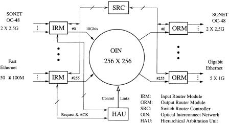
Fig. 11.20 Architecture of a terabit IP router. Ž 1998 IEEE..
51.2 ns required for 64-byte segments transmitted at 10 Gbitrs., demonstrating that arbitration is no longer a bottleneck that limits the switch capacity.
11.4.2A Terabit IP Router Architecture
Figure 11.20 depicts four major elements in the terabit IP router w24x: the OIN supporting nonblocking and high-capacity switching, the Ping-Pong arbitration unit ŽPAU. resolving the output contention and controlling the switching devices, the RMs performing IP packet forwarding, and the RC constructing routing information for the RMs. There are two kinds of RM: input RM ŽIRM. and output RM ŽORM.. Both the IRMs and the ORMs implement IP packet buffering, route Žtable. lookup, packet filtering, and versatile interfaces, such as OC-3, OC12, OC-48, and Gigabit Ethernet. The interconnection between the RC and the RMs can be implemented with dedicated buses or through the OIN. Figure 11.20 simply illustrates the bus-based approach.
11.4.2.1 Speedup The fixed-length segment switching technique is commonly adopted in high-capacity IP routers to achieve high-speed switching and better system performance.
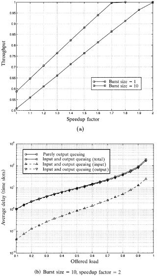
Figure 11.21Ža. suggests that a speedup factor of two is required to achieve nearly 100% throughput under bursty traffic with geometric distribution and an average burst size of 10 packet segments. Figure 11.21Žb. shows the corresponding average delay. The total average delay of input and output queuing is very close to the theoretical bound of purely output queuing. The input delay is an order smaller than the total delay, hinting that an input-
304 OPTICAL PACKET SWITCHES
Fig. 11.21 Switch performance: Ža. throughput, Žb. average delay.
queued switch with speedup 2, on average, will perform as nearly well as a purely output-queued switch.
The speedup induces more challenges in two aspects: Ž1. doubling the switch transmission speed to 10 Gbitrs, and Ž2. halving the arbitration time constraint. The first challenge can be easily met with optical interconnection technology, while the second can be met by the PPA scheme described in Section 11.4.5.
OPTICAL INTERCONNECTION NETWORK FOR TERABIT IP ROUTERS |
305 |
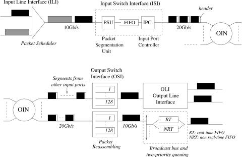
Fig. 11.22 The flow of packets across the router.
11.4.2.2 Data Packet Flow A data segment unit of 64 bytes is chosen to accommodate the shortest IP packets Ž40 bytes.. Variable-length IP packets are segmented before being passed through the switch. Figure 11.22 depicts the flow of packets across the router. A simple round-robin ŽRR. packet scheduler is used at each input line interface ŽILI. to arrange the packet arrivals from different interfaces Žsee also Fig. 11.20.. It uses a FIFO buffer per interface to store incoming packets. Since the output line speed of the scheduler depends on all interfaces, it can be shown that the maximum packet backlog at each input line FIFO is just twice the maximum IP packet size, so the same large buffer can be chosen to avoid any packet loss.
The output packets of the scheduler enter the input switch interface ŽISI. in which packet segmentation takes place. While a packet is being segmented, its IP header is first checked by the input packet filter ŽIPF. for network security and flow classification Ži.e., inbound filtering., as shown in Figure 11.20. Afterwards, the header is sent to the input forwarding engine ŽIFE. for IP table lookup, deciding which ORMŽs. this packet is destined for.
Data segments are stored in a FIFO while waiting for arbitration before being forwarded through the OIN. The forwarding sequence is packet by packet, not cell by cell, for each ISI, in order to simplify the reassembly. The input port number is added to each segment before it enters the OIN for ensuring correct packet reassembly at output ports.
Segments of a packet arriving at an output port may be interleaved with those from other input ports. While a packet is being reassembled, its IP
306 OPTICAL PACKET SWITCHES
header can be sent to the output packet filter ŽOPF. for outbound filtering and then to the output forwarding engine ŽOFE. for another IP route lookup to decide which outgoing interfaceŽs. this packet should be destined for. The packets are then broadcast at the output line interface ŽOLI. to all desirable interfaces. Each interface can maintain two FIFOs supporting two traffic priorities: real-time ŽRT. and non-real-time ŽNRT. packets.
11.4.3Router Module and Route Controller
The RMs interconnected by the OIN perform packet forwarding in a distributed manner, as shown in Figure 11.20. The tasks of running unicast and multicast routing protocols and other control protocols are carried out by the RC centrally in order to expedite the data transport at each RM. Each RM mainly consists of inputroutput line interface ŽILIrOLI., switch interface ŽISIrOSI., packet filter ŽIPFrOPF., and forwarding engine ŽIFErOFE.. The line interfaces terminate OC3, OC12, OC-48, or Gigabit Ethernet connections. The switch interfaces bridge the line interfaces and the OIN for switching. The packet filters check inbound and outbound packets for network security and flow classification. The forwarding engines perform distributed IP route lookup. Below the forwarding engines and the switch interfaces are now described.
11.4.3.1Input and Output Forwarding Engines The IP route lookup function is performed by the IFE and the OFE in each IRM and ORM,
respectively, as shown in Figure 11.20. Several high-speed route lookup techniques have recently been proposed w48, 49, 50, 47, 51x. IFEs and OFEs show slight difference in performing packet forwarding.
An IFE, when receiving an incoming packet, will first validate its IP header. If the header is invalid, the packet is simply discarded. Otherwise, the IFE will determine whether this packet belongs to control messages or data, and then proceed accordingly. For control messages, the IFE forwards the packet via a control path, such as a PCI bus, or through the OIN to the RC. For data, depending on whether this packet is for unicast or multicast,
the IFE will perform unicast or multicast table lookup, find out its destined ORMŽs., and pass this information to the ISI. The ISI will then forward the packet via the OIN to the ORMŽs., as will be described in Section 11.4.3.2.
Since the control messages are handled by IFEs, OFEs deal with data only. Refer to Section 11.4.2.2. An OFE performs similar IP route lookup for received packets, determines their outgoing interfaces to the next-hop router
or host, and passes this information to the OSI. The OSI will then forward each packet to its outgoing interfaceŽs., as will be described in the following.
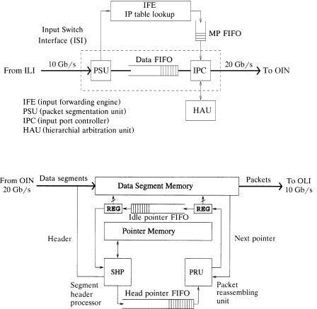
11.4.3.2Input and Output Switch Interfaces Figures 11.23 and 11.24
depict the components and the functions within an ISI and an OSI, respectively. The functions of an ISI include: Ž1. packet segmentation, Ž2. buffering
OPTICAL INTERCONNECTION NETWORK FOR TERABIT IP ROUTERS |
307 |
Fig. 11.23 Input switch interface.
Fig. 11.24 Output switch interface.
of data segments, and Ž3. controlling the segment forwarding at the input port of the OIN. While a packet starts being segmented, its IP header is extracted and sent to the IPF for inbound filtering, then to the IFE, which handles IP table lookup and outputs the destination information wcalled the multicast pattern ŽMP.x of the packet into a MP FIFO. Meanwhile, a one-bit header is added to each segment to indicate whether it is the last segment of a packet. This information is used to determine the packet boundary. The segments are buffered in a data FIFO with its HOL segment entering the IPC for transmission. The IPC fetches the multicast pattern from the MP FIFO whenever the first segment of a packet comes. In every time slot, the IPC keeps sending the request signals to the PAU, waiting for the grant signals, and updating the multicast pattern for preparing the next request. If all requests are granted, which means the current segment has been forwarded to all its destinations, then the IPC reads a new segment from the
308 OPTICAL PACKET SWITCHES
data FIFO and checks if it is the first segment of a packet. If not, the current MP is used for the segment. If so, the IPC gets a new MP from the MP FIFO and repeats the procedure. Upon being transmitted in the OIN, each segment is marked with a number identifying the input port in order to facilitate packet reassembly at the outputs.
At each OSI, data segments from the OIN are stored in the data segment memory, which is organized as linked lists connecting all segments of each packet as in a shared-memory switch. There is an idle-pointer FIFO keeping the unused memory pointers. A separate pointer memory indexed by the input port number is used to store the head and tail pointers of the linked lists of the packets being transmitted over the OIN to the output. Once all segments of a packet have arrived, the entire linked list is completed and the segment header processor ŽSHP. will forward its head pointer to the head pointer FIFO for packet departure scheduling. The head and tail pointers of the packet, which are no longer necessary, will be deleted from the pointer memory to prepare for the next packet arrival from the same input port. The head pointer FIFO keeps the packets in the order of their Žlast segments’. arrival times. The packet reassembly unit ŽPRU. fetches the HOL packet and schedules its segment transmission.
11.4.3.3 Route Controller The RC in the router performs three main tasks: Ž1. executing routing protocols Žsuch as RIP and DVMRP. and other control protocols Žsuch as ICMP, IGMP, and SNMP., exchanging control messages via the RMs with neighbor routers and network management servers, and maintaining a routing information base ŽRIB. in the system; Ž2. based on the RIB, computing, updating, and distributing the IP unicast or multicast forwarding table walso called the forwarding information base ŽFIB.x for every RM; and Ž3. performing packet filter management. All the communications are through a control plane, which can be implemented either by a specific bus, such as a PCI bus, or by the core switch, such as the OIN.
Because trace data collected from a major Internet service provider ŽISP. backbone router indicate that a few hundred updates can occur per second in the worst case, with an average of 1.04 updates per second w50x, the RC needs to perform fast FIB updates. These include the operations of inserting a new route entry, modifying an old entry with new information such as new or additional outgoing interfaceŽs. for this route, and removing an old entry due to timeout or route changes. Besides, since FIBs are usually organized in a treelike data structure in order to facilitate fast searching, changing a single route can affect a large number of relevant entries in an FIB. Many FIBs are to be updated if they all have this route entry.
To resolve the above challenge, it is suggested to let the RC directly access to each FIB rather than periodically download the full table to each RM, especially when there are only minor changes in the table. Consider the unicast case. Suppose each table size is 32 Mbyte w50x. The width of a PCI