

3D Game Programming All In One (2004)
.pdf468 Chapter 15 ■ Making a Vehicle Model
After we have the vertices placed, we move on to creating the faces joined by the vertices.
t i p
It's important to remember that when we create faces using the Face tool, we click on three vertices in sequence to create one face. The order we click on the vertices is important. To create a face or polygon that is facing toward us, we need to select the vertices in a counterclockwise order, as shown in Figure 15.6. For most cases this is not hard to do, but it's possible to get confused and lose track of the sequence. In this case you can use the Edit, Undo menu item to back up until the sequence is clear. You can also abort any three-vertex sequence by just clicking on the Selection tool (or any other tool) and then clicking back on the Face tool again. Then you can start with a fresh trio of vertices.
3.Starting at the right side (the front of the car), begin creating faces, moving to the left along the top as you proceed, including the window area, as shown in Figure 15.7.
When you reach the left side, you should have something resembling Figure 15.8.
4.After completing the top row of faces, start making faces along the bottom, from the left back over to the right (see Figure 15.9).
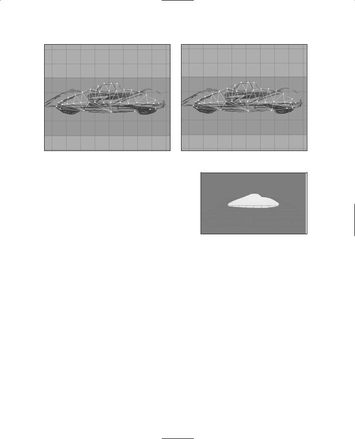
5.Finish up the faces for the side of the body. You should end up with something like Figure 15.10.
Figure 15.6 Vertex order for creating faces.
Okay, so now we have a plane of body faces. We want to make sure they are all oriented correctly. The quickest way to do this is to look at the output in the 3D Perspective view. Make sure the view (it should be the Bottom Right view) is set to
Figure 15.7 Creating faces starting from the |
Figure 15.8 Finishing the top row of faces. |
right. |
Team LRN
The Vehicle Model |
469 |
Figure 15.9 Working the bottom row of faces. Figure 15.10 Completed plane of body faces.
either Flat Shaded or Smooth Shaded by right-clicking on the view and then choosing either Flat Shaded or Smooth Shaded in the pop-up menu.
What you should see is the outline of the body rendered in white or light gray, just as in Figure 15.11.
t i p |
|
Figure 15.11 The 3D view of the initial |
|
body faces. |
|
|
This is a long one, so make sure you've got some pop- |
|
|
corn handy! |
|
|
Sometimes you end up with two overlapping faces: one oriented correctly, and the other reversed. |
|
|
These are hard to catch until they start showing strange results when rendering, as the model grows |
|
|
more complex. There is another way to check for misoriented faces that is a little more involved: |
|
1.Pick the Selection tool and set it to Face mode. Make sure that the Ignore Backfaces check box is selected.
2.Now use the Selection tool to select all the faces by dragging the selection rectangle around all of them. This will highlight all the faces.
3.Now choose Edit, Hide Selection. All of the correctly oriented faces will vanish, leaving behind only the ones facing the wrong way.
4.To fix the problem, unhide all the hidden faces, clear the Ignore Backfaces check box, and select all the faces again. This will select all correct and incorrect faces.
5.Then choose Face, Reverse Vertex Order. This will make the good ones bad, and the bad ones good. Still with me?
6.Okay, now deselect everything by clicking the Select tool in an open area, and select the Ignore Backfaces check box again.
Team LRN
470 Chapter 15 ■ Making a Vehicle Model
7.Drag select over all the faces one more time. Now only the faces that were originally incorrect will be selected.
8.Choose Face, Reverse Vertex Order with those faces selected.
9.Then for one final time clear the Ignore Backfaces check box, select all the faces, and choose Reverse Vertex Order. This should flip all faces back to the correct orientation. If this reminds you of manipulating a Rubik's Cube, then you think a lot like I do!
So now we'll move on to adding some width to the body.
6.Choose the Selection tool and set it to Face mode.
7.Select all the faces.
8.Click the Extrude tool and fill in the X entry of the XYZ boxes with the value10.0 (that's minus ten point zero). Leave Y and Z at 0.0.
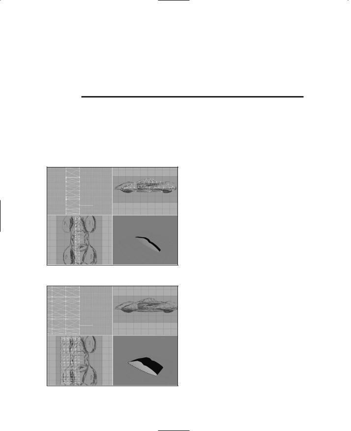
9.Click on the Extrude button to the right of the XYZ boxes. You should get a new set of polygons negatively offset in the X-axis by 10 units, as shown in Figure 15.12.
Notice the way that the image in the 3D view looks—now the body has some depth to it. It's not just a plane of faces anymore.
10.Repeat step 9 four more times, until you get five segments as shown in Figure 15.13. Warning: Do not click
Figure 15.12 First extrusion.
Figure 15.13 After extruding the body faces five times.
on any other tool or in the edit windows. After the fifth extrusion you want to end up with the body faces still selected.
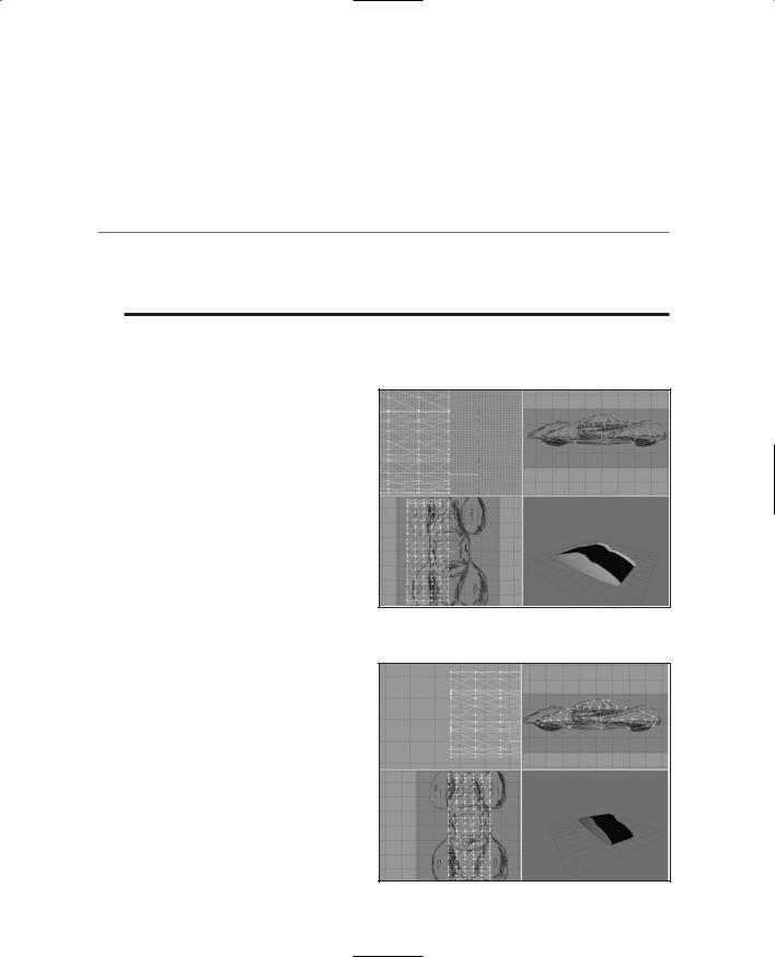
11.The body faces should still be selected if you got my warning in time. Choose Edit, Duplicate Selection.
12.Click the Move tool, then go to the Top view at the lower left, and drag the highlighted faces (these will now be the copies, not the originals) to the right, clear of the extrusion segments, so that you get something like that shown in Figure 15.14.
Team LRN
The Vehicle Model |
471 |
13.Choose Face, Reverse Vertex Order.
14.Using the Side views and Top views, align the vertices of the copy of the body faces with their counterparts in the main body.
15.In the Top view drag the body face copy over to the right edge of the rest of the body polygons. Align the vertices as best you can by eye.
t i p
We want to make sure that the vertices in Step 15 are perfectly aligned. To do this, we'll scale our entire model up. Making our model larger in relation to the grid allows us more precision with the grid. This will help ensure good results when we snap our vertices to the grid, which is going to happen shortly.
16.Select the entire set of polygons in all the faces, and then use the Scale tool to make the entire model four times larger.
17.Select the entire model in vertex selection mode, and choose Vertex, Snap To Grid.
18.Choose Vertex, Weld Vertices.
19.Scale the model by 0.25. This will restore the model back to its original size.
20.In the Top view make sure the entire model is selected, and then use the Move tool to drag the model over the sketch so that it is
aligned around the longitudinal Figure 15.14 After duplicating and moving the
center of the car in the sketch.
You should now have a model that looks like that shown in Figure 15.15.
21.In the Top view select the bottom nine rows (or forwardmost nine rows) of vertices.
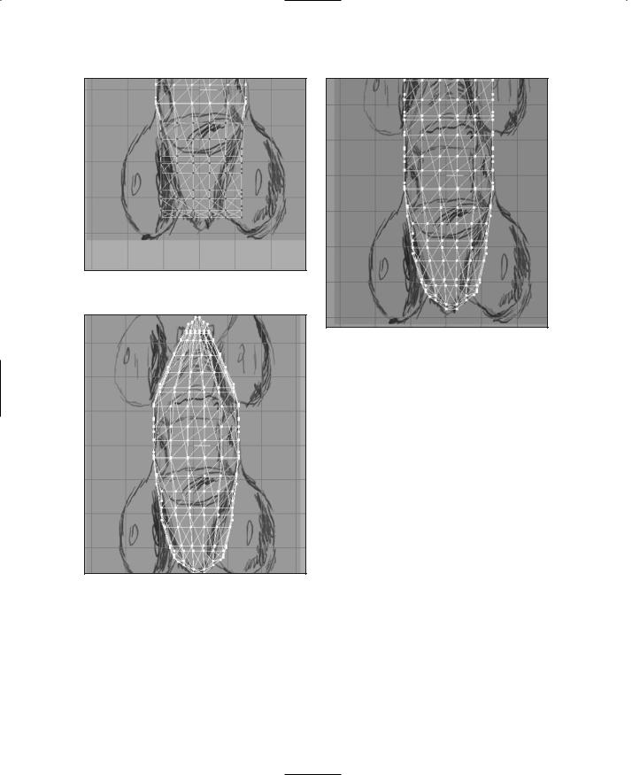
22.Use the Scale tool to scale the selection to 0.9 in the X-axis only; leave the other values at 0.0. Figure 15.16 shows the result of this operation.
23.Change your selection to be the bottom eight rows and scale to 0.9.
copies.
Figure 15.15 Scaling the nose of the runabout.
Team LRN
472 Chapter 15 ■ Making a Vehicle Model
Figure 15.16 After scaling the bottom nine rows.
Figure 15.18 After scaling the tail.
Figure 15.17 After scaling the nose.
24.Repeat the decrementing and scaling of the selection, reducing your selection vertices one row at a time until you run out of victims…ummm…I mean vertices.
You should now have something that resembles that shown in Figure 15.17.
25.Repeat this iterative scaling process for the rows of vertices as seen in the Top view at the other end of the car body, until it, too, tapers, as shown in Figure 15.18. You may find it necessary to manually move a few vertices at either end to achieve the appropriate amount of taper.
26.Now perform the same sort of iterative scaling operations on the Front view of the car, getting it to look something like the view shown in Figure 15.19.
27.Next, use the Selection and Move tools to place the car so that it is centered around the origin (0,0,0), as shown in Figure 15.20. The axis "bug" at the origin has been enhanced as thick black lines to emphasize its location.
28.Finally, select all the polygons and use the Groups tools to regroup all polygons into a single group—name it "body".
Team LRN
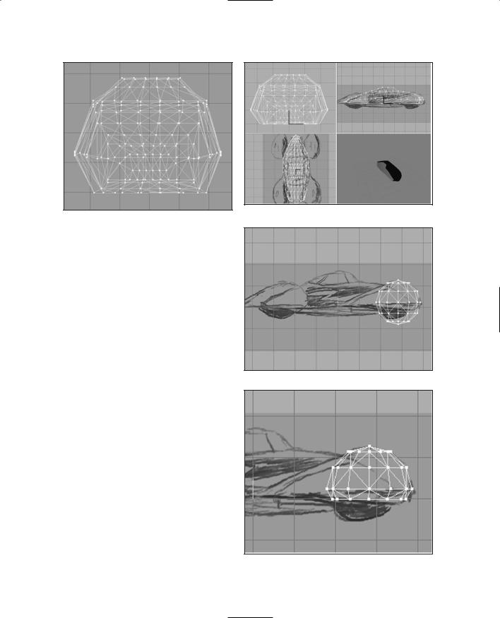
Figure 15.19 Shaping the Front view.
Building the Fenders
Next, we will tackle the wheel well and fender assemblies.
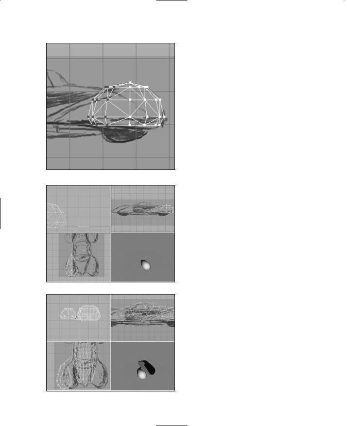
1.Hide the body group.
2.On the Model tab, select the Sphere tool, and create a sphere that matches the forward curves of the forward fender, as shown in Figure 15.21.
3.Select the bottom two rows of faces and delete them. Then move the bottom row of vertices up a bit, to get something that looks like Figure 15.22.
4.Select the leftmost three rows of vertices and move them farther left, as shown in Figure 15.23.
5.Continue to reshape the fender to match the sketch as shown in Figure 15.24, until you are happy.
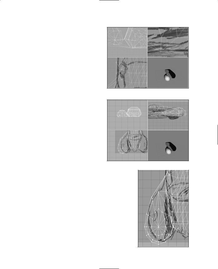
The next bit is a little tricky, so move slowly. We want to drag certain of the vertices from the fender over to the exact position of vertices on the body. The vertex rows
The Vehicle Model |
473 |
Figure 15.20 Centering the Front view.
Figure 15.21 Fender sphere.
Figure 15.22 Lopping off the bottom of the fender sphere.
Team LRN
474 Chapter 15 ■ Making a Vehicle Model
Figure 15.23 Stretching the fender.
Figure 15.24 Shaping the fender.
Figure 15.25 The fender vertices.
we want from the fender are the two bottom ones, and we are interested in the vertices on the body side. By dragging them over to the body, we create a fairing-cum-running board sort of affair.
6.Unhide the body.
7.Drag the fender away from the body so that it is in the clear in the Top and Front views.
8.Select the vertices and drag them, one at a time, as shown in Figure 15.25. The vertices are on the two bottom rows and are the ones that face the body.
Make sure to place the vertices exactly where they mate with a corresponding vertex. A close-up view is shown in Figure 15.26.
9.After each vertex is placed with a mate, use Snap To Grid to make sure they are exactly coincident, and use Weld Vertex to convert each pair of vertices into one vertex. Once you have done this for all the appropriate vertices along the fender bottom, you will get something like Figure 15.27.
10.Finally, move the fender back to a position that matches the sketched fender in the Top view, as shown in Figure 15.28.
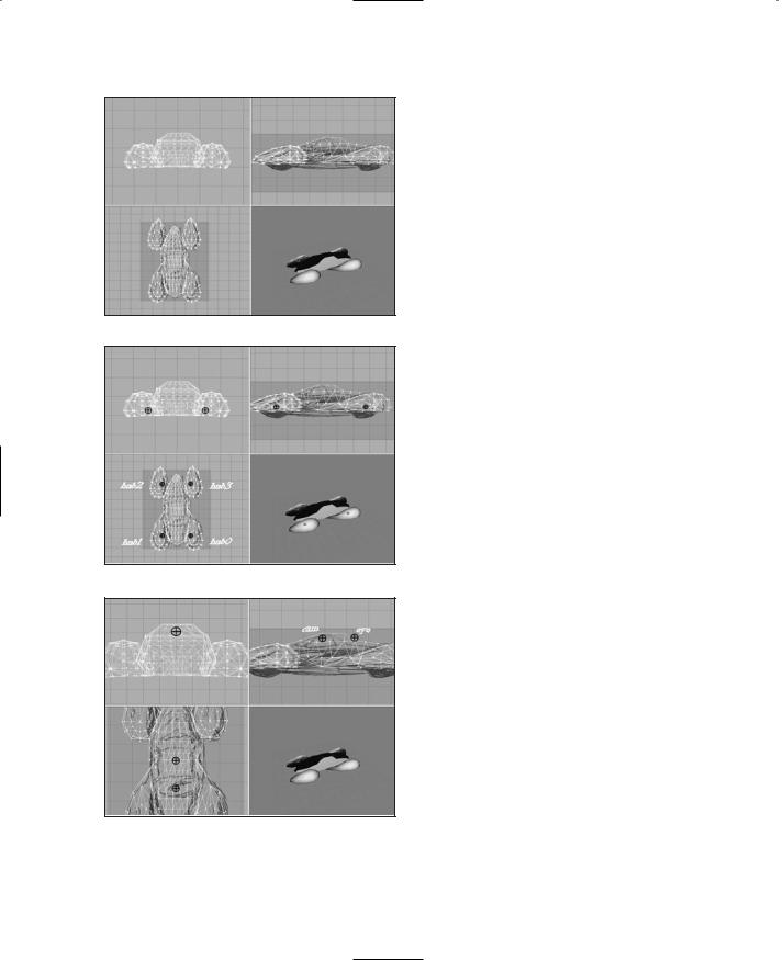
11.Repeat steps 2 to 10 for each of the other fenders. Remember to hide the body and the other fenders when necessary to remove clutter from the screen. You should end up with the finished car as shown in Figure 15.29. But we aren't done yet!
Team LRN
The Vehicle Model |
475 |
The Mount Nodes
In Chapter 14 you learned how to make a skeleton for an animated character in MilkShape using joints. In this section we are going to use the same feature, the joint, to create nodes that tell Torque where to mount certain things on models.
1.As shown in Figure 15.30, create four unconnected joints, or mounts, on the four corners of the car
where the wheel hubs would be. To
ensure that the joints are uncon- Figure 15.26 Close-up of moved vertices. nected, you need to use the Select
tool to deselect each node after it's been created.
2.Name each of the joints with the names shown in Figure 15.30, with hub0 being the left front joint.
3.Add two more unconnected joints to the locations shown in Figure 15.31. Name the front one "eye" and the rear one "cam".
4.Finally, add two unconnected joints
to the locations shown in Figure |
Figure 15.27 All vertices moved. |
|
15.32. Name the one on the right |
|
|
|
|
|
(the left-hand seat position) "mount0" and the other |
||
one "mount1". |
|
|
Now, the last two pairs of mounts are used for different, and mutually exclusive, purposes. The eye and cam mounts are used for games where the car becomes the player's avatar. The sample racing game that comes with Torque works like that. The eye node located at the point of the eye mount is the normal first-person point-of-view location for the view's eye. The cam node is for the thirdperson point of view—the actual camera is offset from the location of this node and so is usually actually behind and above the vehicle.
The mount0 and mount1 mounts are used for games
where the player's character actually gets "in" the vehicle; Figure 15.28 Finished fender.
Team LRN
476 Chapter 15 ■ Making a Vehicle Model
Figure 15.29 All fenders and body completed.
Figure 15.30 Mounts on all four corners.
they specify where the player's avatar will be mounted. The game continues to use the player's avatar's camera and eye nodes. You saw those in use back in Chapter 14.
Skins
Chapter 9 covered the subject of skins and UV mapping, so I refer you back there to map the textures for your new car. You can find a copy of the skin to use at C:\3DGPAi1\RESOURCES\CH15\ runabout.jpg.
Collision Mesh
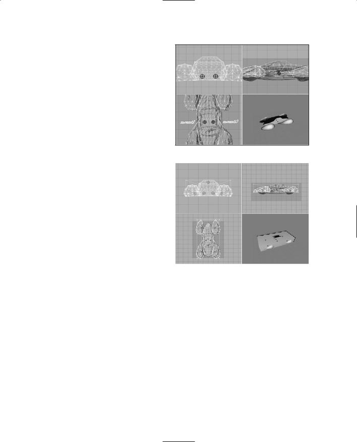
For all objects except player models, we need to create at least one collision mesh if we want the engine to detect when it collides with another object, so use the Box tool in the Model tab to create a box that surrounds the vehicle, as shown in Figure 15.33.
Name the collision mesh "Collision". Any name that starts with "collision" will do, like "Collision-1", "CollisionA", and so on. You can have more than one collision mesh if you like.
You should also hide the collision mesh and then save the model before exporting the model.
The Wheels
Of course, a cool car needs cool wheels. There's not much to them, so I invite you
to model your own wheel for use on the Figure 15.31 Eye and camera mounts. car. You, of course, may decide to make a
complex model, but there is really no need—a lot can be done with a decent skin. A collision mesh is not needed, but do make sure that the wheel is oriented in the views the same as it would appear if attached to the car. Also ensure that the axle of the wheel and
Team LRN
|
Testing Your Runabout |
477 |
the midline of |
the tire are aligned with |
|
the origin bug. |
|
|
Testing Your Runabout
In order to test the runabout, we first need to export it from MilkShape.
1. After saving your work, choose File, Export, Torque Game Engine DTS. You will see the Torque Game Engine (DTS) Exporter dialog box
appear. |
Figure 15.32 |
Seat mounts. |
|
2. Use defaults, but make sure they |
|
|
|
are correct. |
|
|
|
You want to have Export animation |
|
|
|
and Export material information |
|
|
|
selected, and Collision Mesh should |
|
|
|
be set to Collision Meshes (this is |
|
|
|
automatic if the exporter finds a |
|
|
|
mesh whose name starts with "Col- |
|
|
|
lision"). Click OK when ready. |
|
|
|
3. Export your runabout to DTS |
|
|
|
format as C:\3DGPAi1\racing\ |
|
|
|
data\shapes\car\runabout.dts. |
|
|
|
Figure 15.33 |
Collision mesh. |
||
|
4.Open your wheel model and export
it as C:\3DGPAi1\racing\data\shapes\car\wheel.dts.
Next, you need to edit the script that controls the vehicle so it will look for your model and not the default one.
1.Locate the file C:\3DGPAi1\racing\server\scripts\car.cs and open it with UltraEdit.
2.There are two lines that say this:
shapeFile = "~/data/shapes/rifle/weapon.dts";
Replace each of them with this line:
shapeFile = "~/data/shapes/tommygun/tommygun.dts";
3. Then find the line that says this:
shapeFile = "~/data/shapes/buggy/wheel.dts";
Team LRN