

3D Game Programming All In One (2004)
.pdf448Chapter 14 ■ Making a Character Model
Aw shucks, there it is—the head is now rigged! Of course, that's not the end of the story. There is still the rest of the model.
There's also the issue of what to do when a bone is rigged wrong. Sometimes it's a trivial fix, and other times you might have to rerig the whole model. Or you might have to rig a model by attaching a node to just a few vertices rather than a whole mesh or submesh. That can get very, um, fiddly—I guess that would be a reasonable description.
Part of the simplicity in rigging this model comes from the technique we used; building from primitives allows us to easily define meshes and submeshes. We'll use a "one node per mesh" rule of thumb. It can get trickier using other techniques, but sometimes those other techniques might be more appropriate for the model you want to build. It's a judgment call, as everything important tends to be. There is one exception—as there always is—to the "one node per mesh" rule that we'll get out of the way next.
Rigging the Torso
Okay, so the head was a cakewalk. It wasn't even necessary to show any pictures for you to be able to follow along. How about the torso then—duck soup again, no?
Well, yes…I mean no, actually. No duck soup for this one!
The head mesh is attached to the head node, and that is fine. Tilting or rotating the head node will indeed move the head in the manner we want. There really isn't a whole lot to choose from. The neck is more a part of the spine than the head. The camera and mount1 nodes aren't even related to the skeleton. They are special nodes that will have a different role to play in Torque, which we'll cover later. So that leaves the head node to control the head mesh.
The torso, though, has at least five nodes that it might be attached to. But which should it be? Let's eliminate the neck node for now. That leaves the spine nodes or the pelvis node. Actually we can use more than one node for a mesh giving different parts of the mesh to different nodes. When we built the torso mesh, we actually combined two primitives together, remember that? One was the chest cylinder, and the other was the abdomen cylinder. We could have left them as two separate submeshes, but I wanted to show you how to join them together. We can still use them as if they were two separate meshes, by assigning their respective vertices to different nodes.
If you look at the nodes, you'll see that the pelvis node is pretty well the obvious candidate to control the abdomen part of the mesh. The upper spine node, although probably not as obvious, is likely the best candidate for the other node, because it exists in circumstances similar to the pelvis—there are limbs attached. So we'll go with these two and see how that works out.
Team LRN
Character Animation |
449 |
What this will mean in terms of animation is that we can have the vertices that are attached to one node move in one way, while the vertices attached to the other node move differently. Or not. It all depends on how you rig it.
None of this is strictly necessary. The animations we are going to create don't actually require the torso mesh be given more than one node, but it's a good thing to learn, so we'll do it.
1.To get started with rigging the torso, let's tidy up the ol' drawing board a bit by hiding all the meshes except the torso mesh. If you've forgotten how, just go to the Groups tab of the toolbox, choose each mesh, and click Hide. Unfortunately, we can't selectively hide parts of the skeleton. It's either all or nothing when it comes to the bones.
2.Choose the pelvis node in the Joints tab.
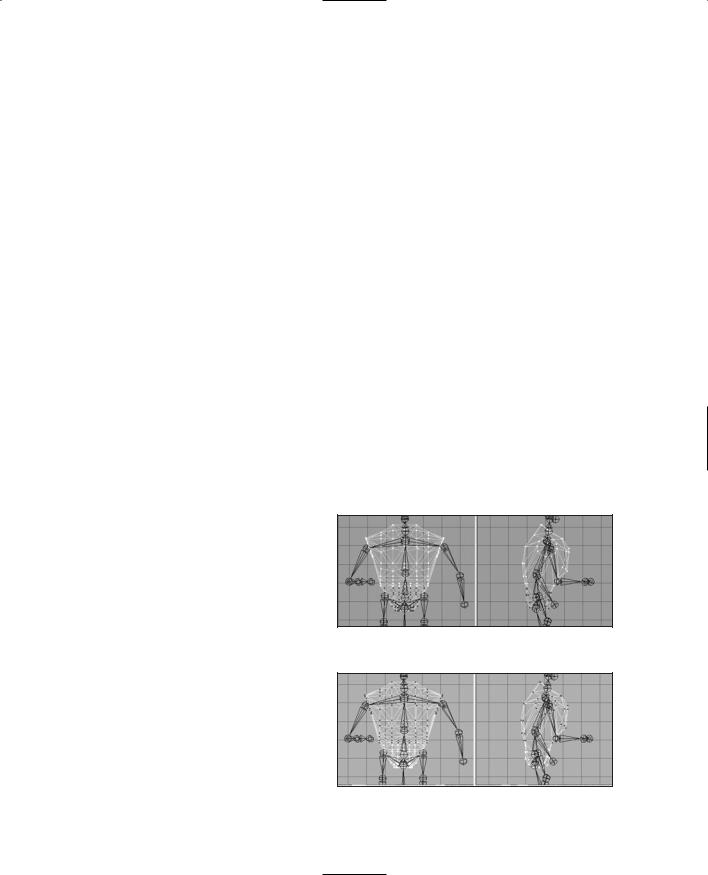
3.Switch to the Model tab and set the Select tool to Vertex mode. Then select the vertices that are the abdomen. You can use either the Front view or the Side view. Figure 14.79 shows the vertices to select.
4.Back in the Joints tab, click Assign. Now the vertices are attached to the pelvis node.
5.Now choose the upper spine node, and then select the vertices for it, using Figure 14.80 as a guide.
6.Click Assign in the Joints tab, and that should do it.
7.Double-check to make sure you didn't overlook any of the vertices by choosing each node in turn, clicking the SelAssigned button, and looking to see which vertices for that node might
have been missed. If you did miss any, you can simply select the node, select the vertices, and then click Assign to add them to the nodes list.
There, that's the torso. It might not have seemed so difficult a task to you, but to me it was a nightmare! Well, maybe not that bad, but it shows you the kinds of decisions you will have to make when rigging your models. What goes where and how best will it work?
Now that we have a few nodes rigged, let's take a look and see what they actually do.
Figure 14.79 The abdomen vertices.
Figure 14.80 The chest vertices.
Team LRN
450 Chapter 14 ■ Making a Character Model
1.If you don't have a button at the lower right called "Anim," then choose Window, Show Keyframer, and make sure there is a check mark there.
2.Click Anim to activate the Keyframer.
3.Using the Select tool in the Joint mode, select the pelvis joint (or you can use the Joints tab to do the selection).
4.Use the Rotate tool in freeform mode in the Right Side view. You will recall that freeform rotation is a simple matter of selecting the Rotate tool, then clicking in the wire-frame view, and dragging the cursor left and right.
Now what you should be seeing is the entire torso, plus the head, rotate around the pelvis. You should also see some strange things as well. The arm, leg, foot, and hand meshes don't move. That's because they aren't rigged yet.
But notice that the leg bones are rotating when you rotate the pelvis. Aha! I don't know about you, but when I bend over, my legs don't move back. Well, not unless I'm floating in water, of course. So the pelvis node, while it seems to be an obvious candidate for bending your character at the waist, looks to not be the right one.
So go back, right now, and change it. It's simply the same procedure I showed you for the pelvis, except you do it for the lower spine node. Make sure to click the Anim button to take it out of the Keyframer first, or you won't be able to make the changes. I'll wait.
Musical Interlude.
There you are. Now that that's done, go back into the Keyframer as I showed you before, and check the rotation of the lower spine node.
Another Musical Interlude.
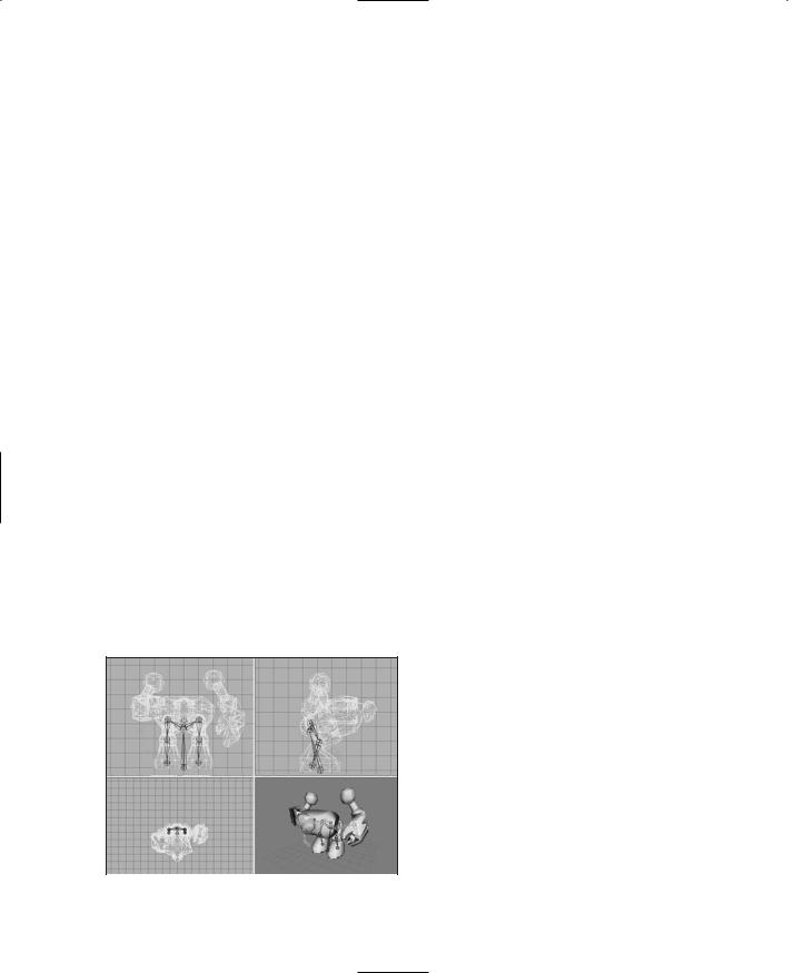
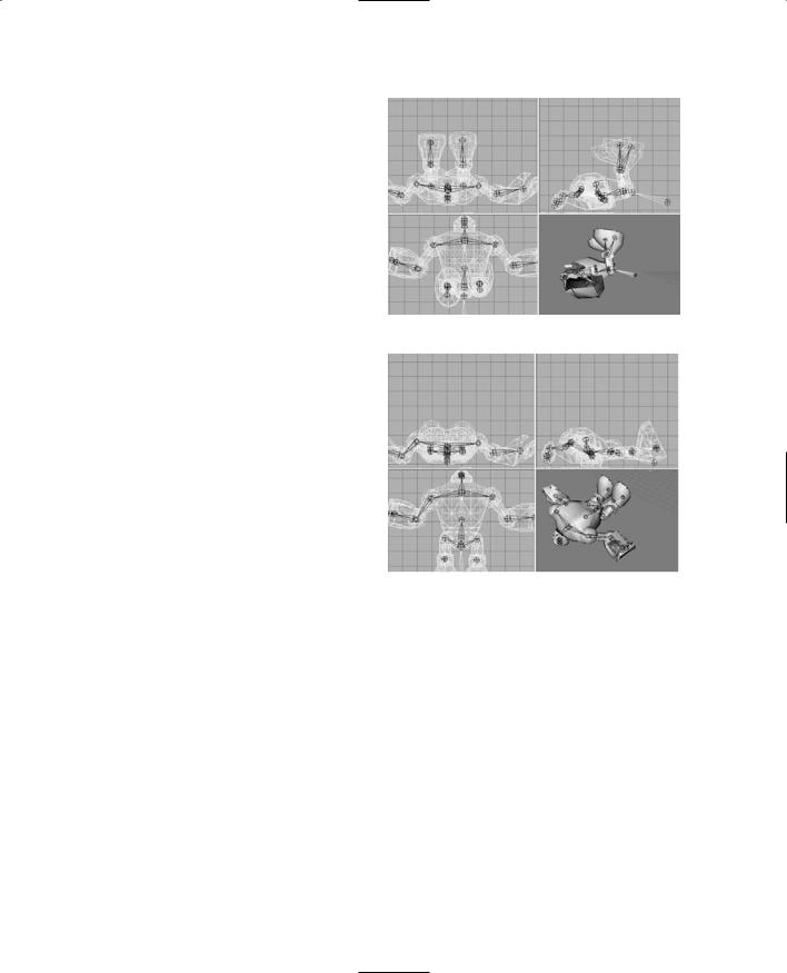
Good! So everything should be working as expected now. The torso and the head meshes bend over in unison, and all the bones attached above the lower spine bend in unison, as shown in Figure 14.81. As you've probably deduced, it is now a reasonably minor matter to rig the rest of the nodes. Use
Table 14.2 to guide you in your rigging.
|
You just need to match a mesh to a node, |
|
attach it, and move on. I'm enjoying the |
|
music here, so you go ahead and do the |
|
rest of the rigging, and I'll sit back and |
|
relax.… |
|
Yet Another Musical Interlude. |
|
Great! With that done, let's move on. |
Figure 14.81 Bending at the lower spine. |
Team LRN
Character Animation |
451 |
|
Table 14.2 |
Hero Rigging |
|
|
Node |
Mesh to Be Rigged |
|
|
ZHead |
Head |
|
|
UpperSpine |
Torso—chest-area vertices |
|
|
LowerSpine |
Torso—abdomen-area vertices |
|
|
LShoulder |
LArm |
|
|
RShoulder |
RArm |
|
|
LElbow |
LHand |
|
|
RElbow |
RHand |
|
|
LHip |
LThigh |
|
|
RHip |
RThigh |
|
|
LKnee |
LFoot |
|
|
RKnee |
RFoot |
|
|
|
|
|
Idle Animation
The idle animation is the one used by Torque when the character is just standing there, doing nothing in particular. In some games you will see some pretty complex idle animation where the character scratches himself in rather inconvenient locations, looks around, scuffs his feet, and so on. We're just going to do a basic breathing sequence so that you'll know that the character is alive. The name for the idle animation in Torque is root.
Even with a basic animation, the watchword is subtlety. Don't overdo it.
1.Make sure the Keyframer is enabled by clicking the Anim button in the lower-right corner.
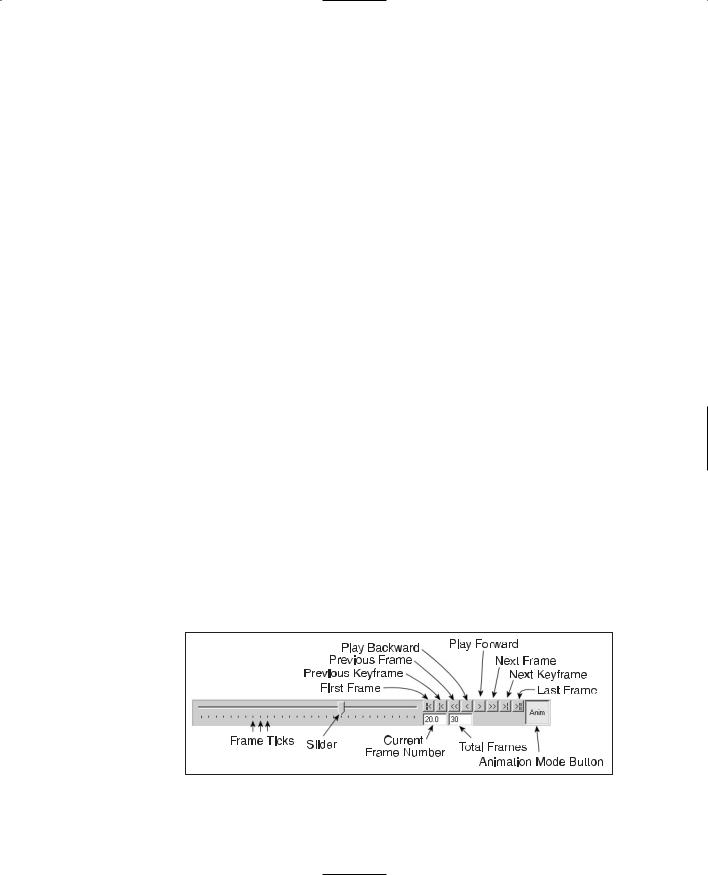
2.Set the number of frames in the Keyframer to 30. Do this in the right-hand edit box in the lower-right corner of the Keyframer (see Figure 14.82).
3.Move the slider to the 1st frame.
Figure 14.82 The Keyframer control panel.
Team LRN
452 Chapter 14 ■ Making a Character Model
4.Choose Animate, Set Keyframe. This indicates that this particular frame is a keyframe.
5.Move the slider to the 15th frame.
6.Take note of the angle of the elbows and hands.
7.Select the midspine node and rotate it 5 degrees around the X-axis.
8.Rotate each of the elbows in the opposite direction by about 5 degrees to place them back where they were before.
9.Choose Animate, Set Keyframe to set the keyframe attribute for this frame.
10.Move the slider back to the 2nd frame.
11.Choose Animate, Copy Keyframes.
12.Move the slider to the 30th frame.
13.Choose Animate, Paste Keyframes.
14.Save your work!
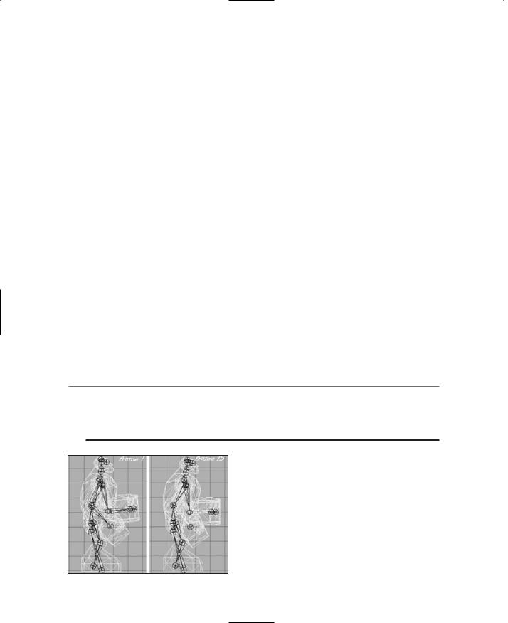
Figure 14.83 shows the subtle pose difference between the 1st and the 15th frames. Now you can test your animation by clicking the Play button on the Keyframer controls. The Play button is the one that looks like a single arrow pointing to the right.
As long as the Play button is down, the animation will loop. If you find it runs too fast, you can change the FPS number in the Preferences dialog box to a lower value to slow the animation.
Notice that when the animation is actually running, that subtle pose change becomes quite noticeable.
t i p
An excellent tool called characterFX is useful for creating animations, and it works well with MilkShape. Unfortunately, for logistical reasons it could not be included with the tools on the companion CD. However, it does a great job of streamlining the process and is flexible, so a quick Google search for it on the Internet might be worth your while!
Run Animation
The run animation is the staple of first-person shooters. Run and shoot, run and shoot. Our Hero character has a somewhat awkward lower body, which will tend to make any animation of him running look a bit goofy. Well, we'll turn that into a feature and capitalize on that goofiness.
Figure 14.83 The difference in poses.
Team LRN
Character Animation |
453 |
1.Set the Keyframer to 120 frames. Additional frames will be added after the 30 you started with for the idle animation.
2.Move the slider to frame 31.
3.Make sure that Operate on Selected Joints Only in the Animate menu is enabled.
4.Rotate the right hip joint slightly and then choose Animate, Set Keyframe. The pose should be similar to the resting pose. The reason why we touched that hip joint at all is to ensure that there is at least one joint in the frame that was affected so that a keyframe will be made. You should have a pose much like that shown in Figure 14.84.
5.Move the slider to frame 40.
6.In the Right Side view, select the Base joint, and move it forward by one grid square and up about three-quarters of a grid square, as shown in Figure 14.85. This movement of the base joint moves the entire model—it's a transformation across the ground. This transformation is necessary in order to notify the Torque
Engine that the model is moving and how fast it is moving. It doesn't need to be precise, but it does need to be there.
7.Select the right hip, and then in the Side view rotate it so that the leg moves forward.
8.Rotate the right knee forward as well, until the leg matches the configuration in Figure 14.85.
9.Repeat the rotations for the left leg and move it backward. In order to get things looking right, you might have to adjust the joint positions slightly by moving them, but not by much.
10.Rotate the left arm using the left shoulder node and the left elbow node, swinging the hand forward until it is approximately opposite the right leg, as shown in Figure 14.85.
11.Set frame 40 to be a keyframe.
12.Move the slider to frame 50. Use Figure 14.86 as the guide for this frame.
13.Move the base node one more grid square to the right, but this time move it back down to the ground level.
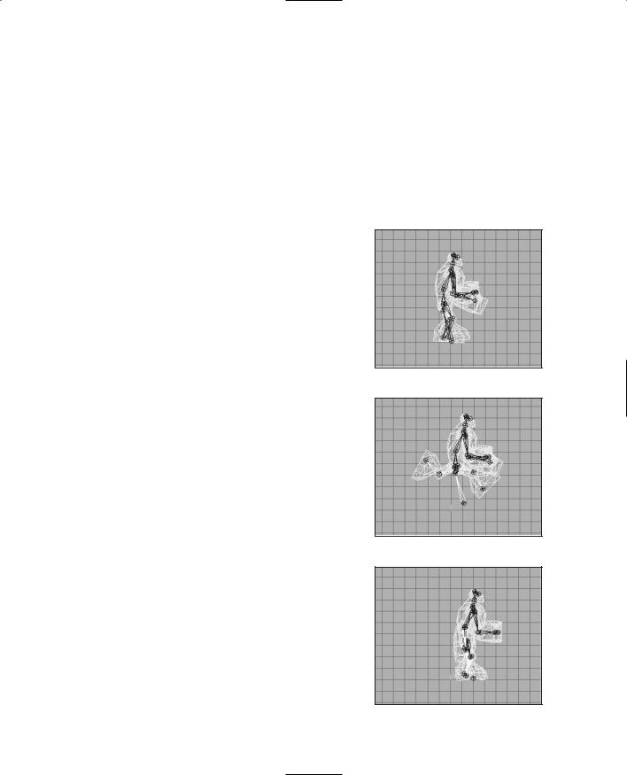
Figure 14.84 Frame 31.
Figure 14.85 Frame 40.
Figure 14.86 Frame 50.
Team LRN
454Chapter 14 ■ Making a Character Model
14.Move all of your legs and joints back to approximately the same configuration as in frame 31.
15.Swing the left arm down to the side of the model.
16.Set this frame (50) to be a keyframe.
17.Move to frame 60. Use Figure 14.87 as the guide for this frame.
18.Pose frame 60 the same as frame 40, except swing the legs in the opposite directions.
19.Swing the left arm back and rotate the elbow so that the left hand comes up parallel to the ground.
20.Set this frame to be a keyframe.
21.Move to frame 70. Use Figure 14.88 as the guide for this frame.
22.Swing the arms and legs back to roughly the pose they had in frame 31.
23.Set this frame to be a keyframe. Use the Play Forward button to watch the animation. If the animation seems to be too fast or too slow, change the FPS setting in the Preferences dialog box until it seems right, and take note of the value you use.
Now you have probably noticed that although we set the pose in only five frames, the program automatically interpolated, or figured out, what the in-between frames should look like. Torque does the same thing for us when we use the model in-game. This is goodness. That's as much of the run animation as we're going to do here, but you should practice working with this for a while. The first place you should start is to set the keyframe exactly in the middle of the ones we've already set—at frames 35, 45, 55, and 65—and adjust the leg positions to get a
better animation from the legs.
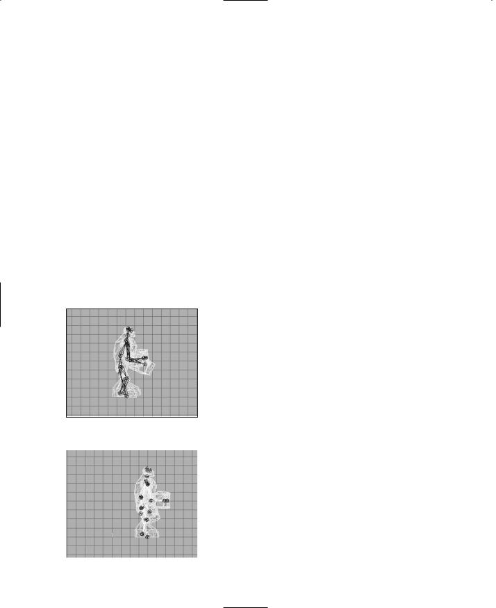
Don't try too hard to make the animation look natural Figure 14.87 Frame 60. though—he's a goofy character and should have that
sort of goofy, cartoonlike appearance when running.
|
Head Animation |
|
This is the animation that Torque automatically |
|
invokes when it needs to know how far your charac- |
|
ter is looking up or down. So basically this anima- |
|
tion's purpose is to define limits or a boundary and |
|
not so much the movement. However, if your charac- |
|
ter's facial or head shape would change when looking |
|
up or down, then you would create a more complex |
Figure 14.88 Frame 70. |
head animation. |
Team LRN
Character Animation |
455 |
That being said, it is really quite quickly dealt with.
1.Move to frame 71.
2.In the Right Side view, rotate the head joint until the head is looking up at the maximum angle you want to allow. You may also need to move the head back a bit.
3.Make this a keyframe.
4.Move to frame 72.
5.Rotate the head joint until the head is pointed down at the maximum angle you want to allow. You may also need to move the head forward a bit.
6.Make this a keyframe also.
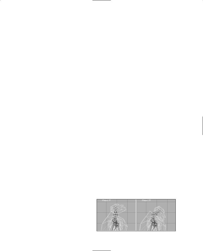
7.Save your work! There, you are done. That's the entire animation sequence! Check your frames against Figure 14.89 to make sure you got it all right.
Headside Animation
In the same way that the head animation defines the limits for the up and down motion performed by Torque, the headside animation provides the limits for the left and right motion. This is most visible from the third-person perspective when in the game.
Do the same thing you did for the head animation, but use frame 73 for the left turn and frame 74 for the right turn. Make each of these frames a keyframe, and save your work when you finish.
Look Animation
The look animation is basically another movement-limiting animation that defines how the character's arms will be posed when he is looking up or down. Again, it is a simple two-frame animation that doesn't require us to go into in detail now. Use frame 75 for the down "look," or aim. Make sure you have both arms positioned sensibly. Use frame 76 for the up aim. Set both as keyframes and save your work again.
Death Animation
As you saw earlier, there are many possible ways to die. Torque supports 11 "standard" death animations, but you can easily
add more by writing a minor code change into the scripts.
We'll cover only one death animation here. We'll have the character collapse backward and fall to the ground on his back with his feet tossing into the air
and back down again. Figure 14.89 Head sequence frames.
Team LRN
456 Chapter 14 ■ Making a Character Model
1.Move to frame 81 and set the pose back to resemble the resting pose as closely as you can, without spending too much time on it.
2.Set this frame to be a keyframe.
3.Move to frame 90 and rotate the arms and hands to match. You can have the character's head pop off temporarily, like I do, or leave it on but thrown back. It's your model! Let Figure 14.90 guide you.
4.Set frame 90 to be a keyframe.
5.Move to frame 100.
6.In the Side view, drag the base node backward several grid squares.
7.Continue to rotate and move the arms and legs, and rotate the body around the pelvis node to make the body tipped past the horizontal with the bottom of the torso higher than the top, as shown in Figure 14.91.
8.If you haven't guessed it by now, make this frame a keyframe!
9.Move to frame 110.
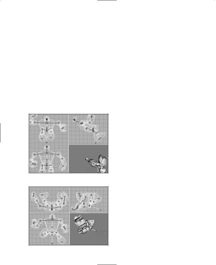
10.The body is hitting the ground, with some momentum still in the legs. Align the bottom of the torso (which is actually the character's back) even with the ground. Rotate the legs and knees to fling the feet up over the body, and rotate the arms to fling them away from the body, as shown in Figure 14.92. By now the base node should be eight or nine grid squares behind the origin along the
Figure 14.90 Frame 90.
Figure 14.91 Frame 100.
Z-axis, as seen in the Side view.
11.Yup, this is another keyframe. Go ahead, make its day.
12.Now for the final resting position. Move to frame 120.
13.Lay the body out, flat against the ground. Also, move the base node one or two more grid squares farther back, to cause the body to slide along the ground. Lay the arms flat to the sides, the feet and legs down on the ground and spread somewhat. Tilt the head back. As you can see in Figure 14.93, he's dead, Jim.
Team LRN
|
|
Character Animation |
457 |
14. Keyframe him, Dano! (Okay, that's |
|
|
|
|
|
|
|
an obscure reference, I'll admit. |
|
|
|
Indulge me!) |
|
|
|
15. Save your work! |
|
|
|
Well, that's the lot of them. Enough ani- |
|
|
|
mations to give you what you really need |
|
|
|
to know to get moving on animating for |
|
|
|
Torque in MilkShape. There's still more |
|
|
|
to cover—we're not quite out of the |
|
|
|
woods yet. Now we have to tell Torque |
|
|
|
how to find the animations. |
|
|
|
Figure 14.92 |
Frame 110. |
|
|
|
|
||
The Animation Sequence Materials |
|
|
|
|
|
|
|
The Torque Engine needs to know where |
|
|
|
the various animations can be found, how |
|
|
|
long they run, what type they are, and |
|
|
|
how fast they should be run. We do this |
|
|
|
using a technique called the Animation |
|
|
|
Sequence Materials. |
|
|
|
The general approach is that we create a |
|
|
|
special material, and embedded in the |
|
|
|
name of that material are the Torque |
|
|
|
name for the animation sequence, its |
|
|
|
Figure 14.93 |
Frame 120. |
|
|
desired playback frame rate, which frames |
|
||
|
|
|
belong to which sequences (inclusive from start to end), and whether the sequence cycles (loops) or plays once per invocation.
You need to go to the Materials tab of the toolbox and create six new materials—one for each animation sequence. Table 14.3 lists the material names you need to use. The text in the "Sequence Material Name" column must all be included in the name, exactly as shown. These special materials tell the Torque DTS Exporter program what special operation to perform on the model as it creates the DTS formatted file for use in Torque.
Note that some of the Sequence Material Names don't include some of the option settings. If you leave them out, the defaults are used. A little later in this chapter you'll find more detail about the exporter.
Finally, there is one more special material we need to make, in order to set the global scale. We built this model on a large scale so we could use the Snap To Grid function without seeing our vertices snapped way out of line. Now, when we export the model, we will need to have it scaled down. Add a material and name it "opt:scale=0.02". This will shrink the model to one-twentieth its created size, which is about right for our needs.
Team LRN