

3D Game Programming All In One (2004)
.pdf438 Chapter 14 ■ Making a Character Model
|
Integrating the Arms to the Torso |
|
Once again, it's integration time. If you are |
|
inclined to wonder about doing the model |
|
this way rather than all at once in one file, I |
|
want to point out that now you have a differ- |
|
ent source model file for each major compo- |
|
nent of your model. This allows you to make |
|
different mix-and-match models using the |
|
same components over and over. Just make |
|
three sets of arms, four sets of legs, five heads, |
|
two torsos, or something like that. Mix 'n' |
|
match 'em and you'll have all sorts of differ- |
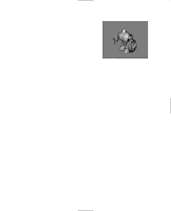
Figure 14.62 The completed arms. |
ent model configurations! |
1.Open the file C:\3DGPAi1\resources\ch14\myhero.ms3d.
2.Select File, Merge, and choose the arms file you just created, which should be called C:\3DGPAi1\resources\ch14\myarms.ms3d.
3.Choose both the right arm and the left arm meshes and move them into position. You should now have a model pretty close to the one shown in Figure 14.63.
The Hero Skin
Now it's time to skin the model. In Chapter 9 you learned how to create the textures for skins, and in Chapter 13 you learned how to do simple UV mapping for skins. Next, we have to do the UV mapping for the player-character, which is somewhat more complex. We are not going to go over the creation of the texture for Hero character skin. The Resources folder includes a mapped Hero skin texture for you to use, but I encourage you to make your own in the same fashion as
the one for the Standard Male.
1. |
If MilkShape is not already running, |
|
|
|
launch it and open your Hero model, |
|
|
located at C:\3DGPAi1\resources\ |
|
|
ch14\myhero.ms3d. |
2. |
Choose File, Export, Wavefront Obj and |
|
|
|
export your Hero model as |
|
|
C:\3DGPAi1\resources\ch14\myhero.obj. |
|
3. |
Launch UVMapper and maximize the |
Figure 14.63 The completed Hero model. |
window. |
|
Team LRN
The Hero Skin |
439 |
4. Load the C:\3DGPAi1\resources\ch14\myhero.obj. You will see a crazy quilt of lines. This is the "default" mapping created by MilkShape. Let's forget about that, because we are going to create our own mapping.
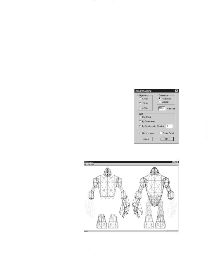
5. Choose Edit, New UV Map, Planar and then use the settings shown in Figure 14.64.
6. |
Choose Edit, Settings, click Color by Group and then click OK. Your screen should |
||
|
now look like Figure 14.65. |
|
|
7. |
First, choose Edit, Select All and press the forward slash ("/") key on the numeric |
||
|
keypad to shrink the selection to 25 percent, half-sized in the x dimension and |
||
|
half-sized in the y dimension (the asterisk ["*"] on the numeric keypad will do the |
||
|
opposite). Press Enter to save your adjustment. If you didn't like the adjustments |
||
|
you just made, press Esc to undo your changes since |
|
|
|
|
||
|
making your last selection or remapping. |
|
|
8. |
Choose Edit, Select by Group, choose the group |
|
|
|
"head", and then click OK. |
|
|
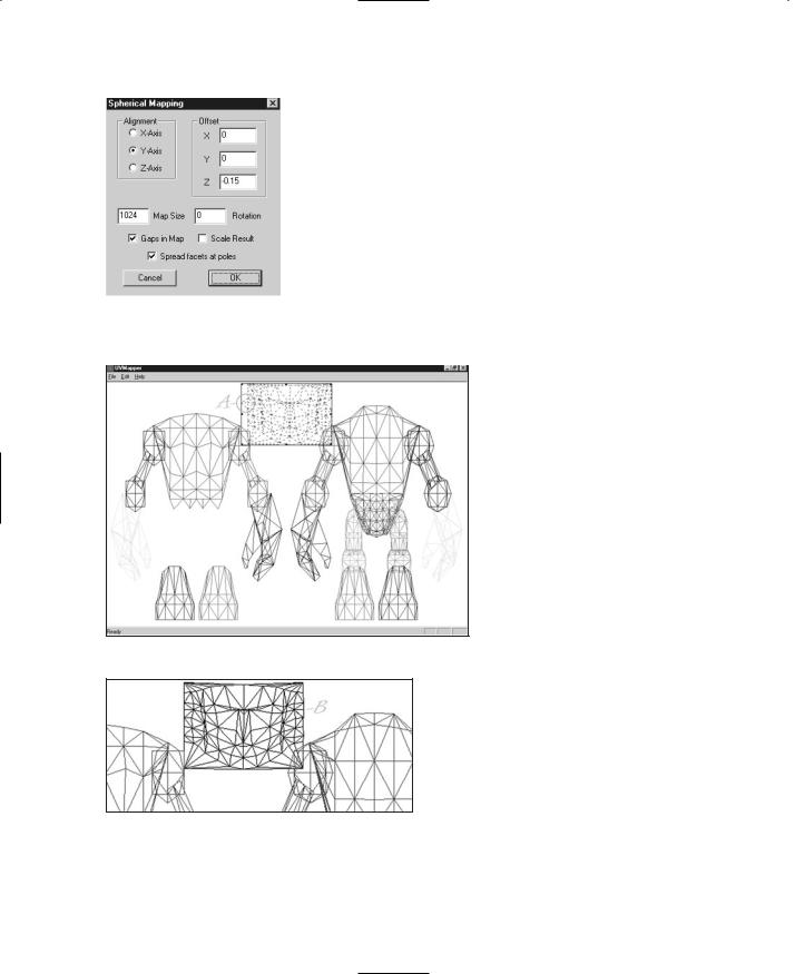
9. |
Choose Edit, New UV Map, Spherical. Use the Spheri- |
|
|
|
cal Settings shown in Figure 14.66. |
|
|
10. |
Press the equal sign ("=") on the numeric keypad to |
|
|
|
expand the head selection to fill the window, and then |
|
|
|
press the numeric keypad "/" a few times to shrink the |
|
|
|
selection. Use your mouse to drag the head to the |
|
|
|
upper center of the window, as shown in Figure 14.67. |
|
|
|
Figure 14.64 Planar |
||
|
Now you might notice that there appear to be two tri- |
||
|
mapping settings for Hero |
||
|
angles out of place in the head unwrapping. Look |
model. |
|
|
inside circle A in Figure |
|
|
|
|
|
|
|
14.67 and see if you can |
|
|
|
spot them. In your |
|
|
|
model this may not be |
|
|
|
the case, but the more |
|
|
|
closely your model |
|
|
|
matches the one I've |
|
|
|
done here, the more |
|
|
|
likely this is to happen. |
|
|
|
This little oddity is easily |
|
|
|
fixed. You should be able |
|
|
|
to do the mapping with- |
|
|
|
out that happening—it's |
|
|
|
all a matter of which set- |
|
|
|
tings you use. You can |
Figure 14.65 The unwrapped Hero model. |
|
Team LRN
440 Chapter 14 ■ Making a Character Model
|
try to get the right settings by trial and error. However, |
||
|
the simplest fix is to just move the miscreants to their |
||
|
lawful location. So that's what we'll do. |
||
|
11. Drag your cursor over the middle of the two wayward |
||
|
triangles. Don't touch any parts of any other triangles |
||
|
in any other part of the model. The triangles will now |
||
|
appear surrounded by a selection box. |
||
|
12. Click and drag them over to the right-hand side where |
||
|
there is that suspicious-looking gap, and place them as |
||
|
well as you can. Location B in Figure 14.68 shows |
||
Figure 14.66 Settings for |
|||
where the triangles end up. |
|||
the spherical mapping of the |
13. Use the arrow keys to adjust the position of the trian- |
||
head. |
|||
|
gles. There you go! |
||
|
|
||
|
|
Now you need to do a bit |
|
|
|
of housekeeping-like fid- |
|
|
|
dling. |
|
|
|
14. Choose Edit, Select, All. |
|
|
|
You will get everything on |
|
|
|
the screen selected in a |
|
|
|
selection box with the lit- |
|
|
|
tle black sizing handles at |
|
|
|
the corners and midway |
|
|
|
along each side. |
|
15. Grab the sizing handle on the right side. Your cursor should change to the left-
Figure 14.67 The unwrapped head. right sizing cursor (this is an arrow pointing left and right).
16. Drag the sizing handle toward the left until you get a blank space on the right a little wider than the width of the head.
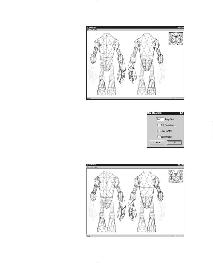
17. Choose Edit, Select, Group and
Figure 14.68 The adjusted triangles. choose the head. Drag it over to the upper right, in the blank space
you just created. You should now have a layout like Figure 14.69.
Team LRN
The Hero Skin |
441 |
As you work you will probably reorganize your layout a few times— that's perfectly normal. You want to keep it clean and make sure your items are easily selectable.
18.Now choose Edit, Select, By Group, and choose the LeftHand group.
19.Choose Edit, New UV Map, Box. You will get
the Box Mapping dialog |
Figure 14.69 The reorganized map. |
|
box, as shown in Figure |
||
|
||
14.70. Make sure you have Split front/back turned off, and |
||
Gaps in Map turned on. Click OK. |
||
The unwrapped left hand will appear in the window, surrounded by the selection box.
20.Move and size the hand mapping, placing it in the center of the window in the blank area. Make sure it is small enough to allow the mapped right hand in here as well (see
Figure 14.71). |
|
Figure 14.70 The |
|
|
|
Box Mapping settings. |
|
21. Perform the same UV mapping operation and placement |
|||
operation on the Right- |
|
|
|
|
|
||
Hand group, putting |
|
|
|
them in the center space. |
|
|
|
22. Next, map the left and |
|
|
|
right feet the same way. |
|
|
|
For each group as you |
|
|
|
unwrap it, size the sole |
|
|
|
(oval shape) so that it is |
|
|
|
longer than it is wide. |
|
|
|
Place the feet under- |
|
|
|
neath the main model, as |
|
|
|
shown in Figure 14.72. |
|
|
|
23. Next, map all the arms |
|
|
|
and legs. Use Planar |
|
|
|
Figure 14.71 |
The UV mapped hands. |
||
mapping for these. |
|||
|
|
||
Team LRN
442Chapter 14 ■ Making a Character Model
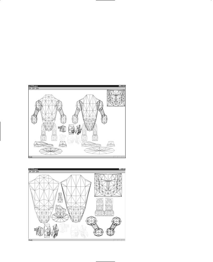
24.Shrink and move the mapped objects, ensuring that no mapped objects overlap any others.
25.Once all the objects are mapped, overlap similar items (with the exception of the torso front and back), and enlarge the torso, hand, and head objects as much as possible. The larger the mapping, the more detail can be applied in the texture.
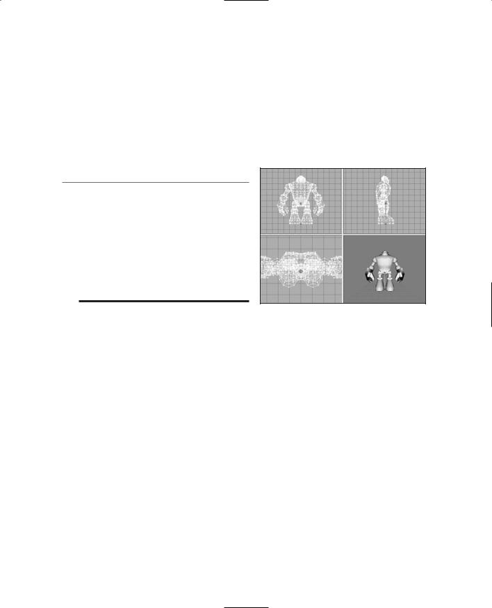
26.Finally, move and arrange the objects to match the layout in Figure 14.73. This is the final texture-mapping layout that we'll use for the template.
27.Choose File, Save Model and save it as C:\3DGPAi1\resources\ch14\myhero.obj (thereby obliterating the one you created from MilkShape; don't worry though— you can always export another from MilkShape if needed).
28.Choose File, Save Texture Map and save the map as C:\3DGPAi1\resources\ ch14\myhero.bmp. Make sure the texture size is set to 512 by 512.
29.Launch MilkShape and create a new file.
30.Choose File, Import, Wavefront Obj and import the C:\3DGPAi1\resources\ ch14\ myhero.obj file.
31.In the Materials Tab of
Figure 14.72 |
The UV mapped feet. |
the toolbox, click New. |
|
|
|
32. Click the top Texture but- |
|
|
|
||
|
|
ton and locate the |
|
|
|
C:\3DGPAi1\resources\ch |
|
|
|
14\myhero.bmp texture |
|
|
|
map template file you cre- |
|
|
|
ated in UVMapper. |
|
|
|
33. Rename the material as |
|
|
|
"heroskin". |
|
|
|
34. Using the Groups tab, |
|
|
|
select all the meshes and |
|
|
|
then switch back to the |
|
|
|
Materials tab and click |
|
|
|
Assign. You should now |
|
|
|
have a 3D view that |
|
Figure 14.73 |
The final UV mapping layout. |
||
resembles Figure 14.74. |
Team LRN
Character Animation |
443 |
Of course, your version is in color. The lines of the triangles in the color groupings assigned in UVMapper are clearly visible. You are now in a position to go ahead and use Paint Shop Pro to create your skin for the Hero model. Refer back to Chapter 9 if you need a refresher. Make sure to save your skin as a JPG file type if you want to minimize file size. This means that you will also have to go back into MilkShape and redefine your material to point at the JPG version and not the BMP version.
We'll continue from here into the animation section using the UV template hero skin that I've included ch14\hero.jpg file.
Figure 14.74 The 3D view showing the UV template texture.
in the C:\3DGPAi1\resources\
Character Animation
Well, a static model, no matter how cool looking when it's standing there, is not terribly interesting in a first-person shooter. We're going to have to animate that sucker!
If we were a big name, big money shop, we might go out and hire a motion capture studio to make our animations. But we're not—we're indie developers! So we will have to explore other options, and there are some.
On the Internet you can find some stop-motion photography sequences that might help you develop your character animations. There are also freely downloadable files with character animations in them—they will probably have a different skeleton structure than the one we use here, but a certain amount of tweaking can go a long way.
I know someone who manually creates animations using action figures that he poses, changing the poses step by step as he works through the animation, converting what his eye sees into the appropriate frame in his animation program. This is certainly a good low-budget option.
In this book we are going to hand-build our animations, because the point is to learn how to do it. They may not be the best animations in the world (or maybe they will be!), but they will be your very own if you make them yourself. If you need a model, ask a friend or family member to step slowly through whatever it is you are trying to animate, if it's humanly possible. You'd be surprised how helpful that can be. Bribe them with their favorite dessert or something.
Animating Characters in Torque
The general method for making animated characters for use in Torque is to construct a skeleton that corresponds to components of the model and then attach that skeleton to
Team LRN

444Chapter 14 ■ Making a Character Model
the corresponding components in a process called rigging. We then create a sequence of keyframes—essentially a series of skeleton poses. When the Torque Engine wants to animate the model, it calculates the positions of the meshes in the model by the position and rotation of the nodes (the joints where the "bones" of the skeleton connect to each other) based on where the keyframes appear in the animation timeline.
We are going to create six different basic animations:
■root (same as idle in some systems)
■run
■look
■head
■headside
■death
Table 14.1 Torque-Supported Animation Sequences
Sequence Name |
Description |
root |
This is the basic "not doing anything" animation—usually the character is |
|
standing and fidgeting. |
run |
This is the animation used when the character is running forward. |
walk |
When the character's speed is less than running speed, he walks, using this |
|
animation. |
back |
This is the animation used when the character is running backward. |
side |
This is the animation used when the character is running sideways, |
|
sometimes called strafing. |
look |
A simple animation where the character's right arm points where the |
|
character is looking, such as when holding a weapon. |
head |
The head looks up or down depending on where the character is looking. |
fall |
This is the pose of a character, or its animations, when the character is falling |
|
off a cliff or building. |
land |
It's the sudden stop at the end of a fall! |
jump |
This is a jump made while running. |
death1 |
Like it says. One of 11 possibilities. You don't need them all, but like they say, |
|
"Variety is the spice of life, er, death, or something." |
death2-death11 |
Ditto. |
looksn |
This is the same as "look", but with weapon held close. |
lookms |
This is the same as "look", but with arms loose. |
scoutroot |
This is the animation used when the character is astride something like a |
|
motorbike. |
headside |
This is the animation used when the character is turning its head from side |
|
to side. |
Team LRN
|
Character Animation |
445 |
|
|
|
light_recoil |
This is the weapon recoil, used to show the character's reaction to firing a |
|
|
weapon. |
|
sitting |
This is the animation used when the character is seated, like sitting in a car. |
|
celsalute |
This is an animation, activated by Ctrl+S as default, an in-game salute or |
|
|
taunt animation. You can use it for whatever you want. |
|
celwave |
Activated by Ctrl+W as default, this is another in-game salute or taunt |
|
|
animation. |
|
standjump |
This is another jump animation, but this time from a standing pose, like "root". |
|
looknw |
This is another weapon "look" with a variation of the arms loose pose. |
|
|
|
|
These animations correspond to character animation support built into Torque. The names must match the names used by Torque; however, we can add our own arbitrary animations and activate them from within the script programs if we want. There are also other animations that Torque supports that we won't cover here.
n o t e
Torque supports animating in several ways, one of which we are covering in this book, where the animation is embedded with the model in the DTS file. Another system Torque can use is the DSQ or Torque Blended Animation Sequence system, which has two important features: It supports blended animation, where two different animations are played for the same model at the same time, and it supports the separation of animation sequences from the model (DTS) using the sequence files (DSQ) format. Unfortunately, the MilkShape exporter for Torque does not support exporting sequence files. This might change in the future.
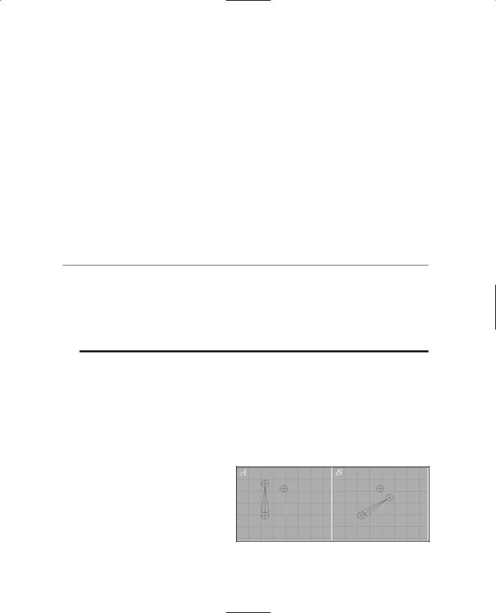
In Figure 14.75 the highlighted (black lines) sphere is a joint, or node. The spike between the two spheres is a "bone." The direction the spike is pointing indicates the relationship between the nodes. The node at the big end is the parent, while the other end is the child node. Notice that in Figure 14.75 the parent node is rotated 60 degrees between frame A and frame B, and the child node follows the rotation. The unattached node doesn't move. Note that the horizontal and vertical lines inside the nodes are angled in the rotated nodes, but not in the unattached node.
Open your myhero.ms3d file, if it isn't already open. Set Joint Size to 3.0 or 4.0 in the Preferences dialog box on the Misc tab. We need to use such a large joint size because the scale of the Hero model is quite a bit larger than the
Standard Male from Chapter 9.
Figure 14.75 Bone movement during joint rotation.
Team LRN
446 Chapter 14 ■ Making a Character Model
Building the Skeleton
Before we can create the animations, we need to construct the character's skeleton. We build the skeleton from the "bottom up" so to speak, beginning with the base node, and working toward the outer extremities.
1.We will start with the base node (or joint), which we place at the origin: (0,0,0).
2.Now make sure that the base node is selected, and then place another node roughly in the groin area. Figure 14.76 shows the relative appearance of these nodes. Make sure that the big end of the bone that joins these two joints is at the end where the base node is.
3.Rename the new node as "pelvis".
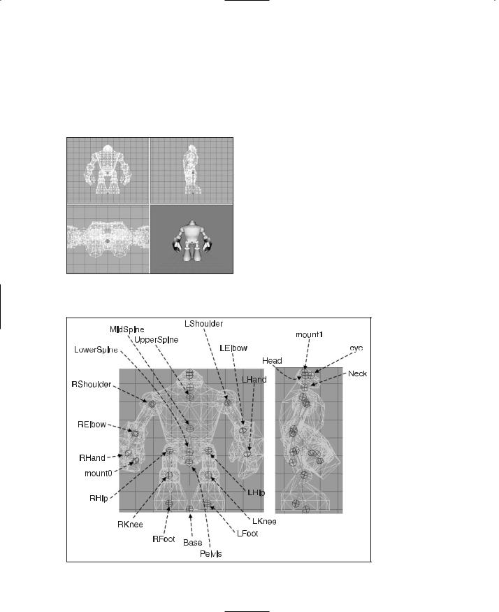
4.Add all the new nodes and label them appropriately. Figure 14.77 provides a guide to the node placement and their
Figure 14.76 Placing the base and pelvis |
names. |
|
nodes. |
||
|
Figure 14.77 The Hero skeleton with labeled nodes.
Team LRN
Character Animation |
447 |
5.Adjust the mesh rotations to match the pose in Figure 14.78. You want the character slightly bent at the knees, with his left arm slightly bent beside him and the right arm bent up at 90 degrees. Starting with the base node and moving on to the pelvis, hips, and shoulders (in that order), adjust the joints of the skeleton. Remember to rotate hip, knee, elbow, and shoulder joints to move the joints at the extremities. Pay particular attention to the placement of the pelvis, lower spine, and hip nodes. The pelvis should be well below the level of the hip nodes, and they should be just a tad higher than the lower spine.
n o t e
The node names and bones you see in Figure 14.77 are not in any way standard.They don't have to be. However, there are standard skeletons for other games that you can use. Torque also has a standard biped skeleton that is the same as the one used for CounterStrike. But we can't really take advantage of it, because it is only useful with sequence files, which we do not yet have the ability to use given the current DTS Exporter that is available. So we may as well use our own skeleton.
Figure 14.78 The pose-adjusted skeleton.
Rigging: Attaching the Skeleton
Now we have the skeleton built, the nodes have been named, and the bones are aligned into a pose we like. Next we are going to attach our model to the skeleton. That way, when the skeleton is manipulated, the mesh of the model will follow suit. It is during this step that you might be inclined to thank me for insisting that you retain mesh groups for the different model components like arms and feet and so on!
Rigging the Head
We'll begin with the head, just to get a feel for the rigging operation.
1.In the Joints tab in the toolbox, choose the joint (or node) named "head". Make sure it appears highlighted in red in the wire-frame views.
2.Switch to the Groups tab and choose the head mesh. It should appear highlighted in red, as you already know.
3.Switch back to the Joints tab and click Assign. Now the head mesh is assigned to the head node. To double-check, just click anywhere in a blank space in a wireframe view to make sure that no objects are selected, choose the head joint to ensure it is selected, and then click the SelAssigned (Select Assigned) button. The head mesh should appear highlighted. If not, go back and repeat these three steps.
Team LRN