

What is a Microcontroller (Paralax, v2.2, student guide, 2004)
.pdf
|
|
|
Chapter #7: Measuring Light · Page 203 |
|
|
|
|
eepromAddress VAR |
Byte |
|
|
DEBUG "Retrieving measurements", CR, CR, |
|
||
"Measurement |
Value", CR, |
|
|
"---------- |
-----", |
CR |
|
|
|
|
|
FOR eepromAddress = 0 TO 58 |
STEP 2 |
|
|
READ eepromAddress, Word time |
|
||
DEBUG DEC2 eepromAddress, |
" |
", DEC time, CR |
|
NEXT |
|
|
|
END
How ReadLightMeasurementsFromEeprom.bs2 Works
As with the WRITE command, the READ command uses byte-size addresses. Since words are being read from the EEPROM, the eepromAddress variable has to have 2 added to it each time through the FOR…NEXT loop.
FOR eepromAddress = 0 to 58 STEP 2
The READ command gets the word size value at eepromAddress. This value is loaded into the time variable.
READ eepromAddress, Word time
The value of the time and eepromAddress variables are displayed as columns in a table in the Debug Terminal.
DEBUG DEC2 eepromAddress, " |
", DEC time, CR |
NEXT
Your Turn – Plotting the Stored Data
√Modify ReadLightMeasurementsFromEeprom.bs2 so that it displays the data to Stamp Plot Lite. Remember, the DEBUG statement must only display the value and a carriage return.
ACTIVITY #4: SIMPLE LIGHT METER
Light sensor information can be communicated in a variety of ways. The light meter you will work with in this chapter changes the rate that the display flickers depending on the light intensity it detects.
Page 204 · What’s a Microcontroller?
Light Meter Parts
(1) Photoresistor
(1) Resistor – 220 Ω (red-red-brown)
(1) Capacitor – 0.01 µF
(1) Capacitor – 0.1 µF
(1) 7-segment LED display
(8) Resistors – 1 kΩ (brown-black-red)
(6) Jumper wires
Building the Light Meter Circuit
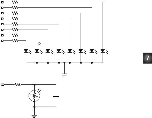
Figure 7-9 shows the 7-segment LED display and photoresistor circuit schematics that will be used to make the light meter, and Figure 7-10 shows a wiring diagram of the circuit. The photoresistor circuit is the same one you have been using in the last two activities, and the 7-segment LED display circuit is the one that was controlled by the BASIC Stamp in Chapter #6.
Chapter #7: Measuring Light · Page 205
1 kΩ |
|
|
|
|
|
|
P15 |
|
|
|
|
|
|
P14 |
|
|
|
|
|
|
P13 |
|
|
|
|
|
|
P12 |
|
|
|
|
|
|
P11 |
|
|
|
|
|
|
P10 |
|
|
|
|
|
|
P9 |
|
|
|
|
|
|
P8 |
|
|
|
|
|
|
E |
C |
DP |
G |
F |
A |
B |
LED’s |
|
|
|
|
|
|
|
|
|
common |
|
|
|
|
|
Vss |
|
|
|
|
P2 |
|
|
|
|
|
|
220 Ω |
|
|
|
|
|
|
|
|
0.01 µF |
|
|
|
|
Figure 7-9
Light Meter
Circuit
Schematic.
Vss
Page 206 · What’s a Microcontroller?
P0 P1 P2 P3 P4 P5 P6 P7 P8 P9 P1 P1 P1 P1 P1 P1 X 0 1 2 3 4 5 2 |
X3 |
|
Vdd |
|
Vni |
|
Vss |
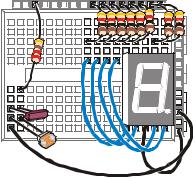
Figure 7-10
Wiring Diagram for Figure 7-9
√Build the circuit shown in Figure 7-9 and Figure 7-10.
√Test the 7-segment LED display to make sure it is connected properly using SegmentTestWithHighLow.bs2 from Chapter #6, Activity #2.
Using Subroutines
Most of the programs you have written so far operate inside a DO…LOOP. Since all the main activity happens inside the DO…LOOP, it is usually called the main routine. As you add more circuits and more useful functions to your program, it can get kind of difficult to keep track of all the code in the main routine. Your programs will be much easier to work with if you organize them into smaller segments of code that do certain jobs. PBASIC has some commands that you can use to make the program jump out of the main routine, do a job, and then return right back to the same spot in the main routine. This will allow you to keep each segment of code that does a particular job somewhere other than your main routine. Each time you need the program to do one of those jobs, you can write a command inside the main routine that tells the program to jump to that job, do it, and come back when the job is done. This process is called executing a subroutine.
Figure 7-11 shows an example of a subroutine and how it’s used. The command GOSUB Subroutine_Name causes the program to jump to the Subroutine_Name: label. When the program gets to that label, it keeps running and executing commands until it gets to a RETURN statement. Then, the program goes back to command that comes after the GOSUB command. In the case of the example in Figure 7-11, the next command is: DEBUG
"Next command".
Chapter #7: Measuring Light · Page 207
DO
GOSUB Subroutine_Name 
 DEBUG "Next command"
LOOP
 Subroutine_Name:
DEBUG "This is a subroutine..." PAUSE 3000
 RETURN
Figure 7-11
How
Subroutines
Work
What’s a label? A label is a name that can be used as a placeholder in your program. GOSUB is one of the commands you can use to jump to a label. Some others are GOTO, ON GOTO, and ON GOSUB. You can use these commands to jump to labels. A label must end with a colon, and for the sake of style, separate words with the underscore character. When picking a name for a label, make sure not to use a reserved word. The rest of the rules for a label name are the same as the ones for naming variables listed in the information box on page 53.
Example Program: SimpleSubroutines.bs2
This example program shows how subroutines work by sending messages to the Debug Terminal.
√Examine SimpleSubroutines.bs2 and try to guess the order in which the DEBUG commands will be executed.
√Enter and run the program.
√Compare the program’s actual behavior with your predictions.
'What's a Microcontroller - SimpleSubroutines.bs2
'Demonstrate how subroutines work.
'{$STAMP BS2}
'{$PBASIC 2.5}
DO
DEBUG CLS, "Start main routine.", CR

Page 208 · What’s a Microcontroller?
PAUSE 2000
GOSUB First_Subroutine
DEBUG "Back in main.", CR
PAUSE 2000
GOSUB Second_Subroutine
DEBUG "Repeat main...", CR
PAUSE 2000
LOOP
First_Subroutine:
DEBUG " Executing first "
DEBUG "subroutine.", CR
PAUSE 3000
RETURN
Second_Subroutine:
DEBUG " Executing second "
DEBUG "subroutine.", CR
PAUSE 3000
RETURN
How SimpleSubroutines.bs2 Works
Figure 7-12 shows how the First_Subroutine call in the main routine (the DO…LOOP) works. The command GOSUB First_Subroutine sends the program to the First_Subroutine: label. The three commands inside that subroutine are executed. When the program gets to the RETURN statement, it jumps back to the command that comes right after the GOSUB command, which is DEBUG "Back in Main.", CR.
What’s a subroutine call? When you use the GOSUB command to make the program jump to a subroutine, it is called a subroutine call.
Chapter #7: Measuring Light · Page 209
PAUSE 2000
GOSUB First_Subroutine 
 DEBUG "Back in main.", CR
 First_Subroutine:
DEBUG " Executing first " DEBUG "subroutine.", CR PAUSE 3000
 RETURN
Figure 7-12
First Subroutine
Call
Figure 7-13 shows a second example of the same process with the second subroutine call (GOSUB Second_Subroutine).
PAUSE 2000
GOSUB Second_Subroutine
 DEBUG "Repeat main...", CR
 Second_Subroutine:
DEBUG " Executing second "
DEBUG "subroutine", CR
PAUSE 3000
 RETURN
Your Turn – Adding and Nesting Subroutines
Figure 7-13
Second Subroutine
Call
You can add subroutines after the two that are in the program and call them from within the main routine.
√Add the subroutine example in the Figure 7-11 on page 207 to SimpleSubroutines.bs2.
Page 210 · What’s a Microcontroller?
√Make any necessary adjustments to the DEBUG commands so that the display looks right with all three subroutines.
You can also call one subroutine from within another. This is called nesting subroutines.
√Try moving the GOSUB that calls Subroutine_Name into one of the other subroutines, and see how it works.
When nesting subroutines the rule is no more than four deep. See the BASIC Stamp Manual for more details. Look up GOSUB and RETURN.
Light Meter Using Subroutines
The segments on the display cycle in a circular pattern that gets faster when the light on the photoresistor gets brighter. When the light gets dimmer, the circular pattern displayed by the 7-segment LED display goes slower.
The program that runs the light meter will deal with three different operations:
1.Read the photoresistor.
2.Calculate how long to wait before updating the 7-segment LED display.
3.Update the 7-segment LED display.
Each operation is contained within its own subroutine, and the main DO…LOOP routine will cycle and call each one in sequence, over and over again.
Example Program: LightMeter.bs2
Controlled lighting conditions make a big difference. For best results, conduct this test in a room lit by fluorescent lights with no direct sunlight (close the blinds). For information on how to calibrate this meter to other lighting conditions, see the Your Turn section.
√Enter and run LightMeter.bs2.
√Verify that the circular pattern displayed by the 7-segment LED display is controlled by the lighting conditions the photoresistor is sensing. Do this by casting a shadow over it with your hand or a piece of paper.
Chapter #7: Measuring Light · Page 211
'What's a Microcontroller - LightMeter.bs2
'Indicate light level using 7-segment display.
'{$STAMP BS2}
'{$PBASIC 2.5}
DEBUG "Program Running!"
index |
VAR |
Nib |
' Variable declarations. |
time |
VAR |
Word |
|
OUTH = %00000000 |
|
' Initialize 7-segment display. |
|
DIRH = %11111111 |
|
|
|
DO |
|
|
' Main routine. |
GOSUB Get_Rc_Time |
|
|
|
GOSUB Delay |
|
|
|
GOSUB Update_Display |
|
|
|
LOOP |
|
|
|
|
|
|
' Subroutines |
Get_Rc_Time: |
|
|
' RC-time subroutine |
HIGH 2 |
|
|
|
PAUSE 3 |
|
|
|
RCTIME 2, 1, time |
|
|
|
RETURN |
|
|
|
Delay: |
|
|
' Delay subroutine. |
PAUSE time |
|
|
|
RETURN |
|
|
|
Update_Display: |
|
|
' Display updating subroutine. |
IF index = 6 THEN index = 0 ' BAFG.CDE LOOKUP index, [ %01000000,
%10000000,
%00000100,
%00000010,
%00000001, %00100000 ], OUTH
index = index + 1
RETURN
Page 212 · What’s a Microcontroller?
How LightMeter.bs2 Works
The first two lines of the program declare variables. It doesn’t matter whether these variables are used in subroutines or the main routine, it’s always best to declare variables (and constants) at the beginning of your program. Since this is such a common practice, this section of code has a name, variable declarations. This name is shown in the comment to the right of the first variable declaration.
index |
VAR |
Nib |
' Variable declarations. |
time |
VAR |
Word |
|
Many programs also have things that need to get done once at the beginning of the program. Setting all the 7-segment I/O pins low and then making them outputs is an example. This section of a PBASIC program also has a name, initialization.
OUTH |
= |
%00000000 |
' Initialize 7-segment display. |
DIRH |
= |
%11111111 |
|
This next segment of code is called the main routine. The main routine calls the Get_Rc_Time subroutine first. Then, it calls the Delay subroutine, and after that, it calls the Update_Display subroutine. Keep in mind that the program goes through the three subroutines as fast as it can, over and over again.
DO |
' Main routine. |
GOSUB Get_Rc_Time |
|
GOSUB Delay |
|
GOSUB Update_Display |
|
LOOP |
|
All subroutines are usually placed after the main routine. The first subroutine’s name is Get_Rc_Time:, and it takes the RC-time measurement on the photoresistor circuit. This subroutine has a PAUSE command that charges up the capacitor. The Duration of this command is small because it only needs to pause long enough to make sure the capacitor is charged. Note that the RCTIME command sets the value of the time variable. This variable will be used by the second subroutine.
|
' Subroutines |
Get_Rc_Time: |
' RC-time subroutine |
HIGH 2 |
|
PAUSE 3 |
|
RCTIME 2, 1, time |
|