

СУБД Oracle / Литература / PowerDesigner 9 / CDM_Tutorial
.pdf&KDSWHU +RZ WR %HJLQ WKH &'0 7XWRULDO
The entities and the relationship are selected. Handles appear around the lasso selection to show that they are selected.
9Drag the entities to a new position.
The relationship moves with the entities.
10Click the 7H[W tool in the palette. The Text tool is now active.
11Click the cursor under the relationship.
Some text appears in the area indicated by the rectangle.
12Click the ULJKW PRXVH EXWWRQ. You release the Text tool.
13Double-click the text. A text box appears.
14Type a short text into the text box.
15Click 2..
The text appears in the diagram. Handles appear around the text.
16Click a handle at the right edge of the text and while continuing to hold the mouse button, drag the cursor to the right until all the text appears. Release the mouse button.
Click on the diagram background. The handles around the text disappear.
17Click the 3RLQWHU tool in the palette.
You will use this tool to select and delete one of the symbols.
18Click on one of the entity symbols.
This selects the object you want to delete.
19Press the DEL key.
CDM Getting Started |
|
8VH WKH WRROV LQ WKH WRRO SDOHWWH
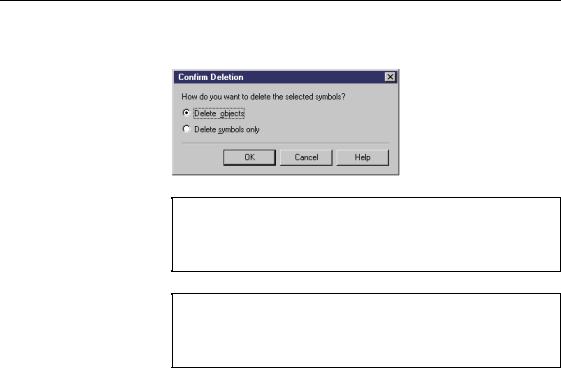
The Confirm Deletion message box appears, asking you how you want to delete the selection.
'HOHWLQJ REMHFWV
If you select Delete object, you erase the graphic symbol and delete the object from the model. If you select Delete Symbols Only, you erase the graphic symbol, but keep the object in the model.
&RQILUP GHOHWLRQ ER[ LV QRW YLVLEOH
If that box does not appear when you want to delete an object, select Tools→General Options from the menu bar then select the Confirm Object Deletion check box.
20Click 2..
The entity and associated relationship are removed from the diagram. The objects are also deleted from the model.
21Click in the remaining entity.
Press SHIFT while you click the text. The two objects are selected.
22Press the DEL key, and click 2. when the deletion message appears. The remaining entity and text are erased.
|
PowerDesigner |

&KDSWHU +RZ WR %HJLQ WKH &'0 7XWRULDO
What you learned In this section, you learned how to use some of the tools in the tool palette. You now know how to:
♦Select a tool
♦Release the active tool either by selecting another tool or by clicking the right mouse button
♦Select all objects of a particular type
♦Move graphic objects
♦Create text to document the CDM
♦Delete objects
CDM Getting Started |
|
2SHQ WKH WXWRULDO &'0
2SHQ WKH WXWRULDO &'0
To perform the rest of the tutorial, you must open the tutorial file. The tutorial file is installed in the directory PowerDesigner 9\Examples\Tutorial.
1Select )LOH→2SHQ.
A file selection window appears.
2Select or browse to the 78725,$/ directory. Select the &'0%()25 &'0 file.
Click 2..
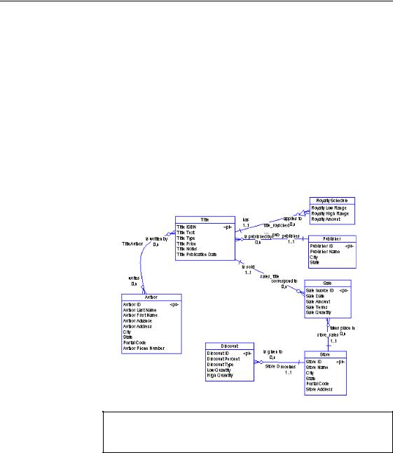
PowerDesigner displays the model in the CDM diagram.
3Press the F8 key to display the whole model in the CDM diagram, if necessary. The model may not look exactly like the one shown below:
$GMXVW GLVSOD\ VFDOH
You can choose the display scale most comfortable for your eyes, by selecting View→Scale and choosing a scale.
|
PowerDesigner |
&KDSWHU +RZ WR %HJLQ WKH &'0 7XWRULDO
'HILQH &'0 SUHIHUHQFHV DQG RSWLRQV
Before you begin working, you will define some display preferences and model options for the CDM.
For a complete description of all CDM preferences and options, see the appropriate PowerDesigner user’s guide.
1Select 7RROV→'LVSOD\ 3UHIHUHQFHV from the menu bar.
The Display Preferences dialog box opens to the General page.
2Select the (QWLW\ node, under the 2EMHFW 9LHZ node, in the &DWHJRU\ tree view.
The Entity page appears.
3Select or clear the following options:
*URXSER[ |
6HOHFWHG LWHP |
|
Entity |
Attributes |
|
|
All attributes |
|
Entity attributes |
Identifier indicators |
|
|
|
For each entity symbol, these preferences display all entity attributes, and identify all attributes that are defined in entity identifiers.
4 Click the 6HW $V 'HIDXOW button.
6HW $V 'HIDXOW
When you click the Set As Default button, you apply the display preferences to the current conceptual diagram in the model, and to any diagram of the same type you will create afterwards.
5Select the 5HODWLRQVKLS node, under the 2EMHFW 9LHZ node, in the &DWHJRU\ tree view.
The Relationship page appears.
6Select or clear the following options:
*URXSER[ 6HOHFWHG LWHP
Relationship Role
CDM Getting Started |
|
'HILQH &'0 SUHIHUHQFHV DQG RSWLRQV
For each entity symbol, these preference displays the role of each relationship in the diagram.
7Click the 6HW $V 'HIDXOW button.
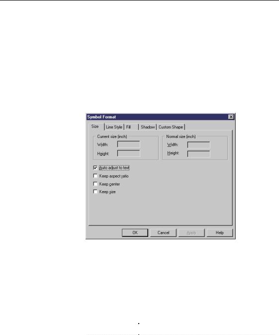
8Click the )RUPDW node. The Format page appears.
9Click the 0RGLI\ button at the bottom right of the page. The Symbol Format page appears.
10Verify that the $XWR DGMXVW WR 7H[W check box is selected (this is the default selection).
11Click 2. in each of the dialog boxes.
You return to the PowerDesigner main window.
12Select 7RROV→0RGHO 2SWLRQV from the menu bar.
The Model Options dialog box appears. The Model node is selected by default in the Category tree view.
13Select or clear the following options:
|
*URXSER[ |
|
6HOHFWHG LWHP |
|
Notation |
|
Mixed |
|
Data Item |
|
Unique code |
|
|
||
|
|
|
Allow reuse |
|
|
PowerDesigner |
|
|
|||
|
|
|
&KDSWHU +RZ WR %HJLQ WKH &'0 7XWRULDO |
|
|
|
|
|
|
|
*URXSER[ |
|
6HOHFWHG LWHP |
|
|
|
|||
|
Relationship |
|
Unique code |
|
|
Domain/Attribute |
|
Data type |
|
|
|
|||
|
Default data type |
|
<UNDEF> |
|
|
|
|||
|
|
|
|
|
'RPDLQ GLYHUJHQFH
Selecting the Data type check box, without selecting the Enforce check box, allows divergence between a domain definition and the data items attached to it. However, when there is divergence, PowerDesigner will propose to update the data type in all data items using the domain
14Select the 1DPLQJ &RQYHQWLRQ node. The Naming Convention page appears.
15Select the 1DPH radio button in the Display groupbox.
Object names are displayed in the object symbols in the CDM diagram.
16Click 2..
CDM Getting Started |
|
'HILQH &'0 SURSHUWLHV
'HILQH &'0 SURSHUWLHV
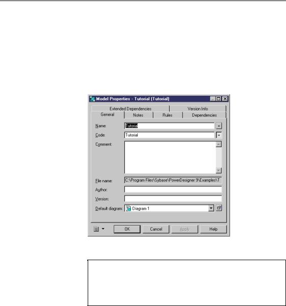
1Select 0RGHO→0RGHO 3URSHUWLHV from the menu bar. The Model property sheet appears.
2Type 7XWRULDO in the Name box.
This is the name of the CDM. The code 7XWRULDO appears automatically in the Code box:
3 Click $SSO\.
1DPH WR FRGH PLUURULQJ
When you type a name in an object property sheet, you may have to type a code also because the name to code mirroring mode may not be selected in the General Options dialog box. To do so, select Tools→General Options→Dialog.
4 Click 2..
|
PowerDesigner |
&KDSWHU +RZ WR %HJLQ WKH &'0 7XWRULDO
6DYH WKH WXWRULDO &'0
You will save the tutorial CDM in another file. This leaves the original tutorial CDM intact so you can use it again if you want to redo the exercises.
1Select )LOH→6DYH $V.
The File Save As dialog box appears.
2Type 78725,$/ &'0 in the File Name box.
This is the name of the file in which you will work and save your modifications.
3Click 6DYH.
This saves your model in the TUTORIAL.CDM file.
6DYH \RXU ZRUN
Save your work periodically while doing these exercises by selecting File→Save.
CDM Getting Started |
|

6DYH WKH WXWRULDO &'0
|
PowerDesigner |