

СУБД Oracle / Литература / PowerDesigner 9 / CDM_Tutorial
.pdfC H A P T E R 9
2UJDQL]LQJ WKH 'LVSOD\
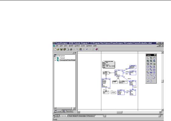
When you finish creating the CDM, you can organize the model using the graphic display options.
What you will do |
In this chapter you will: |
|
|
♦ Add a title box |
|
|
♦ Change the color of the title box |
|
|
♦ Change the color of the window |
|
|
♦ |
Arrange the symbols |
|
♦ Center the model on the page |
|
|
♦ |
Print the model |
+RZ ORQJ ZLOO LW WDNH"
About 15 minutes.
CDM Getting Started |
|
$GG D WLWOH ER[
$GG D WLWOH ER[
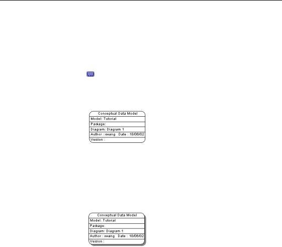
You will add a title box to the model. The title box contains the essential information about the model.
1Click the 7LWOH WRRO from the Palette.
2Click an empty space in the diagram. A title box appears in the diagram.
3Drag the WLWOH ER[ to the top of the model.
4Right-click the title box.
5Select 6KDGRZ from the contextual menu.
A shadow appears behind the title box. You can apply shadow to any symbol in the model.
What you learned In this section, you learned how to:
♦Display the model properties in a title box
♦Apply shadow to a title box
|
PowerDesigner |

&KDSWHU 2UJDQL]LQJ WKH 'LVSOD\
&KDQJH WKH FRORU RI WKH WLWOH ER[
1Right-click the WLWOH ER[.
2Select )RUPDW from the contextual menu. The Symbol Format dialog box appears.
3Click the )LOO tab.
The Fill page appears.
4Select a FRORU in the palette.
5Click 2..
The title box background changes to the selected color.
For information on setting default colors for symbols in the diagram, see the *HQHUDO )HDWXUHV *XLGH.
CDM Getting Started |
|
&KDQJH WKH FRORU RI WKH ZLQGRZ
&KDQJH WKH FRORU RI WKH ZLQGRZ
By changing the window color, you can change the background color of the model.
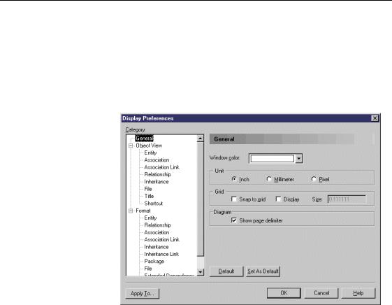
1Select 7RROV→'LVSOD\ 3UHIHUHQFHV.
The Display Preferences dialog box opens to the General page.
2Click the down arrowhead at the end of the :LQGRZ &RORU dropdown listbox.
A dropdown color palette appears.
3Select a FRORU from the palette.
4Click 2..
The model background changes to the selected color.
|
PowerDesigner |
&KDSWHU 2UJDQL]LQJ WKH 'LVSOD\
$UUDQJH WKH V\PEROV
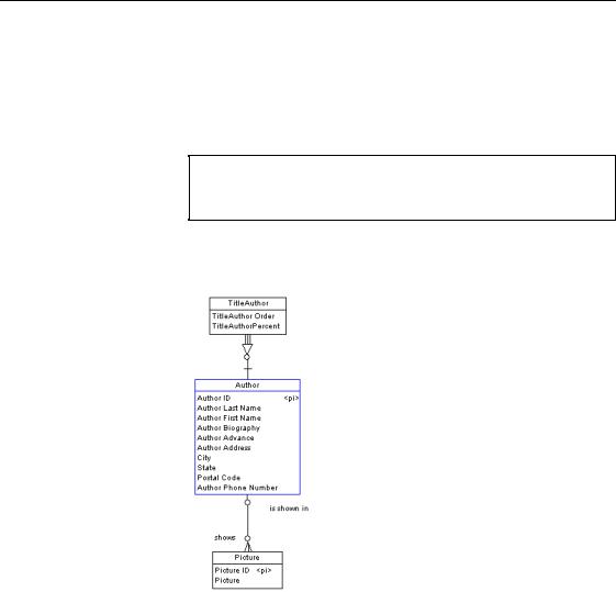
You will align the entity symbols on the left of the model.
1Using the 3RLQWHU WRRO draw a rectangle encompassing the TITLEAUTHOR, AUTHOR and PICTURE entity symbols.
6HOHFWLQJ VHYHUDO V\PEROV DW RQFH
You can also select more than one symbol at a time by pressing the SHIFT key while you click each symbol in turn.
2Select 6\PERO→$OLJQ→&HQWHU RQ 9HUWLFDO $[LV from the menu bar. This aligns the selected symbols along a central vertical axis.
3 Use the $OLJQ menu to align the other symbols.
CDM Getting Started |
|
$UUDQJH WKH V\PEROV
You can align your model as follows:
|
PowerDesigner |
&KDSWHU 2UJDQL]LQJ WKH 'LVSOD\
&HQWHU WKH PRGHO RQ WKH SDJH
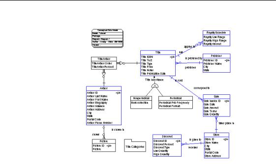
1Select 9LHZ→3DJH 9LHZ→&XUUHQW 3DJH.
This displays the entire current page in the work area. Your model may be spread over two pages, or may be off-center.
2Click the *UDEEHU WRRO in the tool palette.
3Click the GLDJUDP.
This selects the whole model.
4Drag the model to the center of the page.
CDM Getting Started |
|
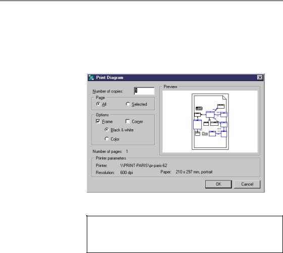
3ULQW WKH PRGHO
3ULQW WKH PRGHO
You can now print the finished model.
1Select )LOH→3ULQW.
The Print Graphics dialog box appears. One page is selected for printing.
2 Click 2..
6HOHFW SDJHV WR SULQW
When a model is spread over several pages you can select and deselect pages for printing by clicking them. Selected pages display a turned down corner.
|
PowerDesigner |

C H A P T E R 1 0
*HQHUDWLQJ WKH 3'0 IURP WKH &'0
What happens when you generate a PDM
Shared DBMS
In this lesson you will generate a Physical Data Model (PDM) from a Conceptual Data Model (CDM).
You generate a PDM for a particular Database Management System (DBMS). Before you generate the PDM, you must select the DBMS referred to as the target database. PowerDesigner translates the data types specified in the CDM into the physical data types which the target database supports.
The correspondence between conceptual and physical data types is defined in a DBMS definition file. There is a DBMS definition file for each type of target database.
You will use a DBMS definition file that is shared with a master DBMS file in .XML format stored in the DBMS library. This file can be used by any number of models. Any modifications to the master DBMS definition file are available to all models using the DBMS in share mode.
Copy DBMS |
A copy of the master DBMS definition file is saved with the model. Any |
||
definition |
modifications made to the DBMS are only available to the current model. |
||
PDM translation |
When you generate a PDM, PowerDesigner also translates the following |
||
|
conceptual objects into the following physical objects: |
||
|
&RQFHSWXDO REMHFW |
|
3K\VLFDO REMHFW |
|
|
||
|
Entity |
|
Table |
|
Entity attribute |
|
Table column |
|
|
||
|
Primary Identifier |
|
Primary key |
|
|
||
|
Relationship |
|
Reference |
|
|
||
|
Identifier |
|
Alternate key |
|
|
||
|
|
|
|
CDM Getting Started |
|
*HQHUDWH WKH 3'0
What you will do In this lesson you will:
♦Generate the PDM
♦Save and close the PDM
♦Save CDM and exit PowerDesigner
+RZ ORQJ ZLOO LW WDNH"
About 5 minutes.
|
PowerDesigner |