

- •Block Reference
- •Commonly Used
- •Continuous
- •Discontinuities
- •Discrete
- •Logic and Bit Operations
- •Lookup Tables
- •Math Operations
- •Model Verification
- •Model-Wide Utilities
- •Ports & Subsystems
- •Signal Attributes
- •Signal Routing
- •Sinks
- •Sources
- •User-Defined Functions
- •Additional Math & Discrete
- •Additional Discrete
- •Additional Math: Increment — Decrement
- •Run on Target Hardware
- •Target for Use with Arduino Hardware
- •Target for Use with BeagleBoard Hardware
- •Target for Use with LEGO MINDSTORMS NXT Hardware
- •Blocks — Alphabetical List
- •Command-Line Information
- •Command-Line Information
- •Command-Line Information
- •Command-Line Information
- •Command-Line Information
- •Command-Line Information
- •Command-Line Information
- •Command-Line Information
- •Command-Line Information
- •Command-Line Information
- •Command-Line Information
- •Command-Line Information
- •Command-Line Information
- •Command-Line Information
- •Command-Line Information
- •Command-Line Information
- •Settings Pane
- •Measurements Pane
- •Signal Statistics Measurements
- •Settings Pane
- •Transitions Pane
- •Overshoots/Undershoots
- •Cycles
- •Settings Pane
- •Peaks Pane
- •Command-Line Information
- •Command-Line Information
- •Command-Line Information
- •Command-Line Information
- •Command-Line Information
- •Command-Line Information
- •Command-Line Information
- •Command-Line Information
- •Command-Line Information
- •Function Reference
- •Model Construction
- •Simulation
- •Linearization and Trimming
- •Data Type
- •Examples
- •Main Toolbar
- •Command-Line Alternative
- •Command-Line Alternative
- •Command-Line Alternative
- •Command-Line Alternative
- •Command-Line Alternative
- •Command-Line Alternative
- •Mask Icon Drawing Commands
- •Simulink Classes
- •Model Parameters
- •About Model Parameters
- •Examples of Setting Model Parameters
- •Common Block Parameters
- •About Common Block Parameters
- •Examples of Setting Block Parameters
- •Block-Specific Parameters
- •Mask Parameters
- •About Mask Parameters
- •Notes on Mask Parameter Storage
- •Simulink Identifier
- •Simulink Identifier
- •Model Advisor Checks
- •Simulink Checks
- •Simulink Check Overview
- •See Also
- •Identify unconnected lines, input ports, and output ports
- •Description
- •Results and Recommended Actions
- •Capabilities and Limitations
- •Tips
- •See Also
- •Check root model Inport block specifications
- •Description
- •Results and Recommended Actions
- •See Also
- •Check optimization settings
- •Description
- •Results and Recommended Actions
- •Tips
- •See Also
- •Description
- •Results and Recommended Actions
- •See Also
- •Check for implicit signal resolution
- •Description
- •Results and Recommended Actions
- •See Also
- •Check for optimal bus virtuality
- •Description
- •Results and Recommended Actions
- •Capabilities and Limitations
- •See Also
- •Description
- •Results and Recommended Actions
- •Capabilities and Limitations
- •See Also
- •Identify disabled library links
- •Description
- •Results and Recommended Actions
- •Capabilities and Limitations
- •Tips
- •See Also
- •Identify parameterized library links
- •Description
- •Results and Recommended Actions
- •Capabilities and Limitations
- •Tips
- •See Also
- •Identify unresolved library links
- •Description
- •Results and Recommended Actions
- •Capabilities and Limitations
- •See Also
- •Results and Recommended Actions
- •Capabilities and Limitations
- •See Also
- •Results and Recommended Actions
- •Capabilities and Limitations
- •See Also
- •Check usage of function-call connections
- •Description
- •Results and Recommended Actions
- •See Also
- •Check signal logging save format
- •Description
- •Results and Recommended Actions
- •See Also
- •Description
- •Results and Recommended Actions
- •See Also
- •Description
- •Results and Recommended Actions
- •Tips
- •See Also
- •Check data store block sample times for modeling errors
- •Description
- •Results and Recommended Actions
- •See Also
- •Check for potential ordering issues involving data store access
- •Description
- •Results and Recommended Actions
- •Tips
- •See Also
- •Check for partial structure parameter usage with bus signals
- •Description
- •Results and Recommended Actions
- •Tips
- •See Also
- •Check for calls to slDataTypeAndScale
- •Description
- •Results and Recommended Actions
- •Tips
- •See Also
- •Check for proper bus usage
- •Description
- •Results and Recommended Actions
- •Action Results
- •Tips
- •See Also
- •Description
- •Results and Recommended Actions
- •See Also
- •Description
- •Results and Recommended Actions
- •See Also
- •Check for proper Merge block usage
- •Description
- •Input Parameters
- •Results and Recommended Actions
- •See Also
- •Description
- •Results and Recommended Actions
- •Action Results
- •See Also
- •Check for non-continuous signals driving derivative ports
- •Description
- •Results and Recommended Actions
- •See Also
- •Runtime diagnostics for S-functions
- •Description
- •Results and Recommended Actions
- •See Also
- •Check file for foreign characters
- •Description
- •Results and Recommended Actions
- •Tips
- •See Also
- •Check model for known block upgrade issues
- •Description
- •Results and Recommended Actions
- •Action Results
- •See Also
- •Description
- •Results and Recommended Actions
- •Action Results
- •See Also
- •Check that the model is saved in SLX format
- •Description
- •Results and Recommended Actions
- •Tips
- •See Also
- •Check Model History properties
- •Description
- •Results and Recommended Actions
- •See Also
- •Analyze model hierarchy for upgrade issues
- •Description
- •Results and Recommended Actions
- •Tips
- •See Also
- •Description
- •Results and Recommended Actions
- •See Also
- •Simulink Performance Advisor Checks
- •Simulink Performance Advisor Check Overview
- •See Also
- •Baseline
- •See Also
- •Check Preupdate Items
- •See Also
- •Checks that need Update Diagram
- •See Also
- •Checks that require simulation to run
- •See Also
- •Check Accelerator Settings
- •See Also
- •Create Baseline
- •See Also
- •Identify resource intensive diagnostic settings
- •See Also
- •Check optimization settings
- •See Also
- •Identify inefficient lookup table blocks
- •See Also
- •Identify Interpreted MATLAB Function blocks
- •See Also
- •Check MATLAB Function block debug settings
- •See Also
- •Check Stateflow block debug settings
- •See Also
- •Identify simulation target settings
- •See Also
- •Check model reference rebuild setting
- •See Also
- •Check Model Reference parallel build
- •See Also
- •Check solver type selection
- •See Also
- •Select normal or accelerator simulation mode
- •See Also
- •Simulink Limits
- •Maximum Size Limits of Simulink Models
- •Index
- •Filter Structures and Filter Coefficients
- •Valid Initial States
- •Number of Delay Elements (Filter States)
- •Frame-Based Processing
- •Sample-Based Processing
- •Valid Initial States
- •Frame-Based Processing
- •Sample-Based Processing
- •Model Parameters in Alphabetical Order
- •Common Block Parameters
- •Continuous Library Block Parameters
- •Discontinuities Library Block Parameters
- •Discrete Library Block Parameters
- •Logic and Bit Operations Library Block Parameters
- •Lookup Tables Block Parameters
- •Math Operations Library Block Parameters
- •Model Verification Library Block Parameters
- •Model-Wide Utilities Library Block Parameters
- •Ports & Subsystems Library Block Parameters
- •Signal Attributes Library Block Parameters
- •Signal Routing Library Block Parameters
- •Sinks Library Block Parameters
- •Sources Library Block Parameters
- •User-Defined Functions Library Block Parameters
- •Additional Discrete Block Library Parameters
- •Additional Math: Increment - Decrement Block Parameters
- •Mask Parameters

Variant Subsystem
Variant
Specify the name of the variant to use if you select Override variant conditions and use the following variant.
Settings
Default: ''
Must be a valid MATLAB identifier.
Tips
You can use the Variant drop-down list to see a list of all variant objects currently in the base workspace.
Dependencies
Enable variants and Override variant conditions and use the following variant enable this parameter.
Command-Line Information
Parameter: OverrideUsingVariant
Type: string
Value: Name of the Simulink.Variant object
See Also
•“Overriding Variant Conditions”
•Simulink.Variant
2-2016

Variant Subsystem
Generate preprocessor conditionals
Control whether generated code contains preprocessor conditionals for this Variant Subsystem block.
Settings
Default: Disabled
Dependencies
•The check box is available for generating only ERT targets.
•Override variant conditions and use following variant is cleared ('off')
•Model Configuration Parameters > Optimization > Signals and Parameters > Inline parameters is selected ('on')
•Model Configuration Parameters > Code Generation > Interface > Generate preprocessor conditionals is set to Use local settings.
Command-Line Information
Parameter: GeneratePreprocessorConditionals
Type: string
Value: 'off' | 'on'
Default: 'off'
See Also
•“Set Up Variant Subsystems”
•“Variant Systems”
2-2017

Vector Concatenate, Matrix Concatenate
Purpose |
Concatenate input signals of same data type to create contiguous |
|
output signal |
Library |
Math Operations, Signal Routing |
Description |
The Concatenate block concatenates the signals at its inputs to create an |
|
output signal whose elements reside in contiguous locations in memory. |
|
|
|
Tip The Concatenate block is useful for creating an output signal that |
|
is nonvirtual. However, to create a vector of function calls, use a Mux |
|
block instead. |
|
You use a Concatenate block to define an array of buses. For details |
|
about defining an array of buses, see “How to Define an Array of |
|
Buses”. For background information about using an array of buses, see |
|
“Combine Buses into an Array of Buses”. |
|
The Concatenate block operates in either vector or multidimensional |
|
array concatenation mode, depending on the setting of its Mode |
|
parameter. In either case, the block concatenates the inputs from the |
|
top to bottom, or left to right, input ports. |
|
Vector Mode |
|
In vector mode, all input signals must be either vectors or row vectors |
|
[1xM matrices] or column vectors [Mx1 matrices] or a combination of |
|
vectors and either row or column vectors. The output is a vector if all |
|
inputs are vectors. |
|
The output is a row or column vector if any of the inputs are row or |
|
column vectors, respectively. |
|
Multidimensional Array Mode |
|
Multidimensional array mode accepts vectors and arrays of any size. |
|
It assumes that the trailing dimensions are all ones for input signals |
|
with lower dimensionality. For example, if the output is 4-D and the |
|
input is [2x3] (2-D) this block treats the input as [2x3x1x1]. The |
2-2018
Vector Concatenate, Matrix Concatenate
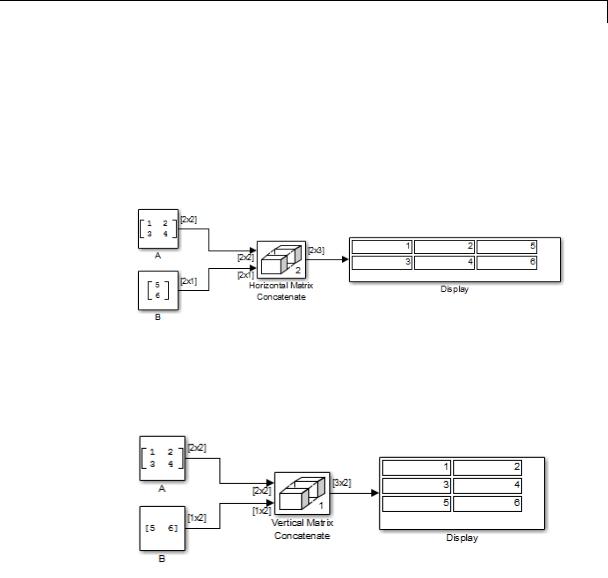
output is always an array. The block’s Concatenate dimension parameter allows you to specify the output dimension along which the block concatenates its input arrays.
If you set the Concatenate dimension parameter to 2 and inputs are 2-D matrices, the block performs horizontal matrix concatenation and places the input matrices side-by-side to create the output matrix, for example:
If you set the Concatenate dimension parameter to 1 and inputs are 2-D matrices, the block performs vertical matrix concatenation and stacks the input matrices on top of each other to create the output matrix, for example:
For horizontal concatenation, the input matrices must have the same column dimension. For vertical concatenation, the input matrices must have the same row dimension. All input signals must have the same dimension for all dimensions other than the concatenation dimensions.
2-2019
Vector Concatenate, Matrix Concatenate
Data Type
Support
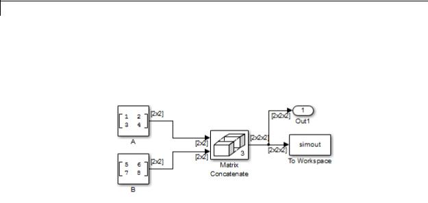
If you set the Mode parameter to Multidimensional array, the Concatenate dimension parameter to 3, and the inputs are 2-D matrices, the block performs multidimensional matrix concatenation, for example:
Accepts signals of any data type that Simulink supports. All inputs must be of the same data type. Outputs have the same data type as the input.
For more information, see “Data Types Supported by Simulink” in the Simulink documentation.
2-2020
Vector Concatenate, Matrix Concatenate
Parameters and Dialog Box
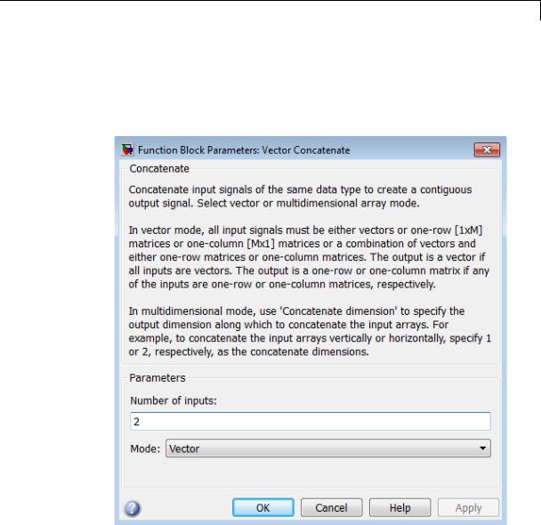
The parameters and dialog box differ, based on the mode in which the block is operating: vector or matrix. Most parameters exist in both modes.
The dialog box for the Vector Concatenate block appears as follows.
2-2021
Vector Concatenate, Matrix Concatenate
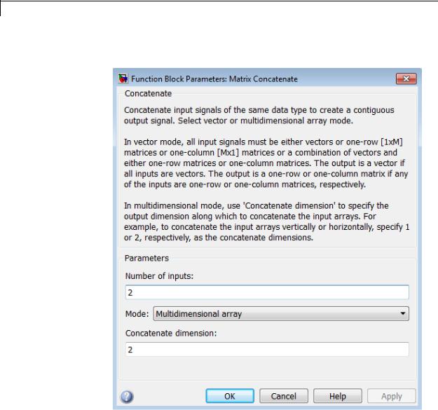
The dialog box for the Matrix Concatenate block appears as follows.
2-2022
Vector Concatenate, Matrix Concatenate
Number of inputs
Specifies the number of inputs for the block.
Settings
Default: 2
Command-Line Information
See “Block-Specific Parameters” on page 8-109 for the command-line information.
2-2023

Vector Concatenate, Matrix Concatenate
Mode
Select the type of concatenation that this block performs.
Settings
Default: Vector (for the Vector Concatenate block), Multidimensional array (for the Matrix Concatenate block)
Vector
Perform vector concatenation (see “Vector Mode” on page 2-2018 for details).
Multidimensional array
Perform matrix concatenation (see “Multidimensional Array Mode” on page 2-2018 for details).
Dependency
This parameter enables Concatenate dimension.
Command-Line Information
See “Block-Specific Parameters” on page 8-109 for the command-line information.
2-2024

Vector Concatenate, Matrix Concatenate
Concatenate dimension
Specifies the output dimension along which to concatenate the input arrays.
Settings
Default: 2
•Enter 1 to concatenate input arrays vertically.
•Enter 2 to concatenate input arrays horizontally.
•Enter a higher dimension to perform multidimensional concatenation on the inputs.
Dependency
Selecting Multidimensional array for Mode enables this parameter.
Command-Line Information
See “Block-Specific Parameters” on page 8-109 for the command-line information.
Characteristics |
|
Direct Feedthrough |
Yes |
|
|
Sample Time |
Inherited from driving block |
|
|
Scalar Expansion |
No |
|
|
Dimensionalized |
Yes |
|
|
Multidimensionalized |
Yes |
|
|
Zero-Crossing Detection |
No |
See Also |
|
cat in the MATLAB reference documentation |
|
2-2025
Weighted Sample Time
Purpose |
Support calculations involving sample time |
Library |
Signal Attributes |
Description |
The Weighted Sample Time block is an implementation of the Weighted |
|
Sample Time Math block. See Weighted Sample Time Math for more |
|
information. |
2-2026

Weighted Sample Time Math
Purpose |
Support calculations involving sample time |
Library |
Math Operations |
Description |
The Weighted Sample Time Math block adds, subtracts, multiplies, |
|
or divides its input signal, u, by a weighted sample time, Ts. If the |
|
input signal is continuous, Ts is the sample time of the Simulink model. |
|
Otherwise, Ts is the sample time of the discrete input signal. |
|
You specify the math operation with the Operation parameter. |
|
Additionally, you can specify to use only the weight with either the |
|
sample time or its inverse. |
|
Enter the weighting factor in the Weight value parameter. If the |
|
weight, w, is 1, that value does not appear in the equation on the block |
|
icon. |
|
The block computes its output using the precedence rules for MATLAB |
|
operators (see “Operator Precedence” in the MATLAB documentation). |
|
For example, if the Operation parameter specifies +, the block |
|
calculates output using this equation: |
|
u + (Ts * w) |
|
However, if the Operation parameter specifies /, the block calculates |
|
output using this equation: |
|
(u / Ts) / w |
Data Type |
The Weighted Sample Time Math block accepts signals of the following |
Support |
data types: |
|
• Floating point |
|
• Built-in integer |
|
• Fixed point |
|
• Boolean |
2-2027

Weighted Sample Time Math
Parameters and Dialog Box
For more information, see “Data Types Supported by Simulink” in the Simulink documentation.
The Main pane of the Weighted Sample Time Math block dialog box appears as follows:
Operation
Specify operation to use: +, -, *, /, Ts Only, or 1/Ts Only.
Weight value
Enter the weight of sample time.
2-2028

Weighted Sample Time Math
Implement using
Select one of two modes: online calculations or offline scaling adjustment. This parameter is visible only when you set
Operation to * or /.
|
Result of (Ts * w) |
Output Data Type |
Block Execution |
|
|
|
of Two Modes |
|
|
|
A power of 2, or an |
The same, when |
Equally efficient in |
|
|
integer value |
Output data |
both modes |
|
|
|
type is Inherit: |
|
|
|
|
Inherit via |
|
|
|
|
internal rule |
|
|
|
Not power of 2 and |
Different |
More efficient for |
|
|
not an integer value |
|
the offline scaling |
|
|
|
|
mode |
|
Note When the Implement using parameter is not visible, operations default to online calculations.
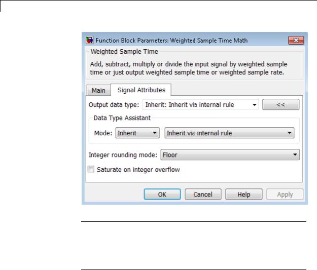
The Signal Attributes pane of the Weighted Sample Time Math block dialog box appears as follows:
2-2029
Weighted Sample Time Math
Tip The Saturate on integer overflow parameter is visible only if:
•The Operation parameter specifies + or -.
•The Operation parameter specifies * or / and the Implement using parameter specifies Online Calculations.
Output data type
Specify whether the block inherits the output data type by an internal rule or back propagation.
2-2030

Weighted Sample Time Math
Tip If you enter an expression in the edit field, the expression must evaluate to one of the two inherit rules.
Integer rounding mode
Specify the rounding mode for fixed-point operations. For more information, see “Rounding”. in the Simulink Fixed Point documentation.
Saturate on integer overflow
|
Action |
Reasons for Taking |
What Happens for |
Example |
|
|
This Action |
Overflows |
|
|
Select this |
Your model has |
Overflows saturate to |
An overflow associated |
|
check box. |
possible overflow, |
either the minimum |
with a signed 8-bit |
|
|
and you want explicit |
or maximum value |
integer can saturate to |
|
|
saturation protection |
that the data type can |
–128 or 127. |
|
|
in the generated code. |
represent. |
|
|
Do not select |
You want to optimize |
Overflows wrap to the |
The number 130 does |
|
this check |
efficiency of your |
appropriate value that |
not fit in a signed 8-bit |
|
box. |
generated code. |
is representable by the |
integer and wraps to |
|
|
You want to avoid |
data type. |
–126. |
|
|
|
|
|
|
|
overspecifying how |
|
|
|
|
a block handles |
|
|
|
|
out-of-range signals. |
|
|
|
|
For more information, |
|
|
|
|
see “Checking for |
|
|
|
|
Signal Range Errors”. |
|
|
|
|
When you select this check box, saturation applies to every |
||
|
|
internal operation on the block, not just the output or result. |
||
|
|
Usually, the code generation process can detect when overflow is |
||
|
|
not possible. In this case, the code generator does not produce |
||
|
|
saturation code. |
|
|
2-2031

Weighted Sample Time Math
Characteristics |
Direct Feedthrough |
For all math operations except Ts and |
|
|
1/Ts |
|
Scalar Expansion |
No, the weight is always a scalar |
|
Zero-Crossing Detection |
No |
|
|
|
2-2032
While Iterator
Purpose |
Repeatedly execute contents of subsystem at current time step while |
|
condition is satisfied |
Library |
Ports & Subsystems |
Description |
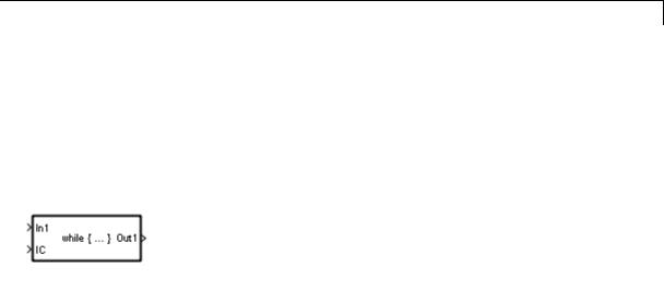
|
The While Iterator block, when placed in a subsystem, repeatedly executes the contents of the subsystem at the current time step while a specified condition is true.
Note Placing a While Iterator block in a subsystem makes it an atomic subsystem if it is not already an atomic subsystem.
The output of a While Iterator subsystem cannot be a function-call signal. Otherwise, Simulink displays an error when you simulate the model or update the diagram.
You can use this block to implement the block-diagram equivalent of a C program while or do-while loop. In particular, use While loop type to select one of the following while loop modes:
•do-while
In this mode, the While Iterator block has one input, the while condition input, whose source must reside in the subsystem. At each time step, the block runs all the blocks in the subsystem once and then checks whether the while condition input is true. If the input is true, the iterator block runs the blocks in the subsystem again. This process continues as long as the while condition input is true
2-2033

While Iterator
Data Type
Support
and the number of iterations is less than or equal to the Maximum number of iterations.
•while
In this mode, the iterator block has two inputs: a while condition input and an initial condition (IC) input. The source of the initial condition signal must be external to the while subsystem. At the beginning of the time step, if the IC input is true, the iterator block executes the contents of the subsystem and then checks the while condition input. If the while condition input is true, the iterator executes the subsystem again. This process continues as long as the while condition input is true and the number of iterations is less than or equal to the Maximum number of iterations. If the IC input is false at the beginning of a time step, the iterator does not execute the contents of the subsystem during the time step.
Tip Specify a maximum number of iterations to avoid infinite loops, which you can break only by terminating MATLAB.
Acceptable data inputs for the condition ports are any numeric data type that Simulink supports, as well as any fixed-point type that includes a 0 value. For more information, see “Data Types Supported by Simulink” in the Simulink documentation.
The optional output port can output any of the following data types: double, int32, int16, or int8.
2-2034
While Iterator
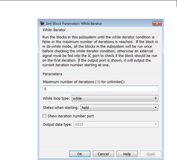
Parameters and Dialog Box
Maximum number of iterations
Specify the maximum number of iterations allowed. A value of -1 allows any number of iterations as long as the while condition input is true. Note that if you specify -1 and the while condition never becomes false, the simulation will run forever. In this
2-2035

While Iterator
case, the only way to stop the simulation is to terminate the MATLAB process. Therefore, do not specify –1 as the value of this parameter unless you are certain that the while condition becomes false at some point in the simulation.
While loop type
Specify the type of while loop that this block implements.
States when starting
Set this field to reset if you want the iterator block to reset the states of the blocks in the while subsystem to their initial values at the beginning of each time step (i.e., before executing the first loop iteration in the current time step). To cause the states of blocks in the subsystem to persist across time steps, set this field to held (the default).
Show iteration number port
If you select this check box, the While Iterator block outputs its iteration value. This value starts at 1 and is incremented by 1 for each succeeding iteration. By default, this check box is not selected.
Output data type
If you select the Show iteration number port check box (the default), this field is enabled. Use it to set the data type of the iteration number output to int32, int16, int8, or double.
Examples The While Iterator block can optionally output the current iteration number, starting at 1. The following model uses this capability to compute N, where N is the first N integers whose sum is less than 100.
2-2036

While Iterator
The contents of the While Iterator subsystem are:
The While Iterator block uses the following parameter settings:
•Maximum number of iterations set to 20
•States when starting set to reset
The model is the diagrammatic equivalent of the following pseudocode:
max_sum = 100; sum = 0;
iteration_number = 0; cond = (max_sum > 0); while (cond != 0) {
2-2037

While Iterator
iteration_number = iteration_number + 1; sum = sum + iteration_number;
if (sum > max_sum OR iteration_number > max_iterations) cond = 0;
}
Characteristics |
Direct Feedthrough |
No |
|
Sample Time |
Inherited from the driving block |
|
Scalar Expansion |
No |
|
Dimensionalized |
No |
|
Zero-Crossing Detection |
No |
|
|
|
2-2038
While Iterator Subsystem
Purpose |
Represent subsystem that executes repeatedly while condition is |
|
satisfied during simulation time step |
Library |
Ports & Subsystems |
Description |
|
The While Iterator Subsystem block is a Subsystem block that is preconfigured to serve as a starting point for creating a subsystem that executes repeatedly while a condition is satisfied during a simulation time step.
See the While Iterator block and “Control Flow Logic” for more information.
When using simplified initialization mode, you cannot place any block needing elapsed time within an Iterator Subsystem. In simplified initialization mode, Iterator subsystems do not maintain elapsed time, so Simulink will report an error if any such block (such as the Discrete-Time Integrator block) is placed within the subsystem. For more information on simplified initialization modes, see “Underspecified initialization detection”.
2-2039

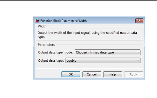
Width
Purpose |
Output width of input vector |
Library |
Signal Attributes |
Description |
The Width block generates as output the width of its input vector. |
|
You can use an array of buses as an input signal to a Width block. For |
|
details about defining and using an array of buses, see “Combine Buses |
|
into an Array of Buses”. |
Data Type
Support
The Width block accepts real or complex signals of the following data types:
•Floating point
•Built-in integer
•Fixed point
•Boolean
•Enumerated
The Width block also supports mixed-type signal vectors.
When the Output data type mode is not Choose intrinsic data type, the block supports only built-in numeric types. For more information, see “Data Types Supported by Simulink” in the Simulink documentation.
2-2040
Width
Parameters and Dialog Box
Note The Width block ignores the Data type override setting of the Fixed-Point Tool.
Output data type mode
Specify the output data type to be the same as the input, or inherit the data type by back propagation. You can also choose to specify a built-in data type from the drop-down list in the Output data type parameter.
Output data type
This parameter is visible when you select Choose intrinsic data type for Output data type mode. Select a built-in data type from the drop-down list.
Characteristics |
Sample Time |
Constant |
|
Dimensionalized |
Yes |
|
|
|
2-2041

Width
Multidimensionalized |
Yes |
Zero-Crossing Detection |
No |
|
|
2-2042
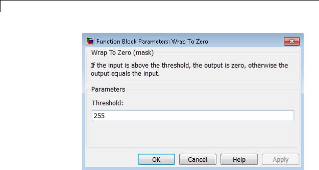
Wrap To Zero
Purpose |
Set output to zero if input is above threshold |
Library Discontinuities
Description The Wrap To Zero block sets the output to zero when the input is above the Threshold value. However, the block outputs the input when the input is less than or equal to the Threshold.
Data Type The Wrap To Zero block accepts inputs of the following data types:
Support
•Floating point
•Built-in integer
•Fixed point
•Boolean
The block output has the same data type as the input. For more information, see “Data Types Supported by Simulink” in the Simulink documentation.
Tip If the input data type cannot represent zero, parameter overflow occurs. To detect this overflow, go to the Diagnostics > Data Validity pane of the Configuration Parameters dialog box and set Parameters > Detect overflow to warning or error.
2-2043
Wrap To Zero
Parameters and Dialog Box
Threshold
When the input exceeds the threshold, the block sets the output to zero.
Characteristics |
Direct Feedthrough |
Yes |
|
Scalar Expansion |
Yes |
|
Multidimensionalized |
Yes |
|
Zero-Crossing Detection |
No |
|
|
|
2-2044

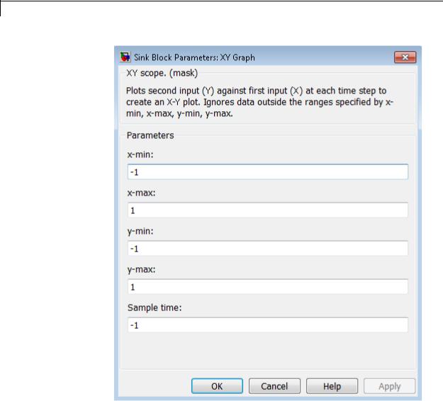
XY Graph
Purpose |
Display X-Y plot of signals using MATLAB figure window |
Library Sinks
Description The XY Graph block displays an X-Y plot of its inputs in a MATLAB figure window.
The block has two scalar inputs. The block plots data in the first input (the x direction) against data in the second input (the y direction). (See “How to Rotate a Block” for a description of the port order for various block orientations.) This block is useful for examining limit cycles and other two-state data. Data outside the specified range does not appear.
A figure window appears for each XY Graph block in the model at the start of simulation.
Data Type The XY Graph block accepts real signals of the following data types:
Support
•Floating point
•Built-in integer
•Fixed point
•Boolean
For more information, see “Data Types Supported by Simulink” in the
Simulink documentation.
2-2045
XY Graph
Parameters |
|
|
and |
x-min |
|
Dialog |
||
Box |
Specify the minimum x-axis value. The default is -1. |
|
x-max |
||
|
||
|
Specify the maximum x-axis value. The default is 1. |
2-2046

XY Graph
y-min
Specify the minimum y-axis value. The default is -1.
y-max
Specify the maximum y-axis value. The default is 1.
Sample time
Specify the time interval between samples. To inherit the sample time, set this parameter to -1. See “Specify Sample Time” in the Simulink documentation for more information.
2-2047
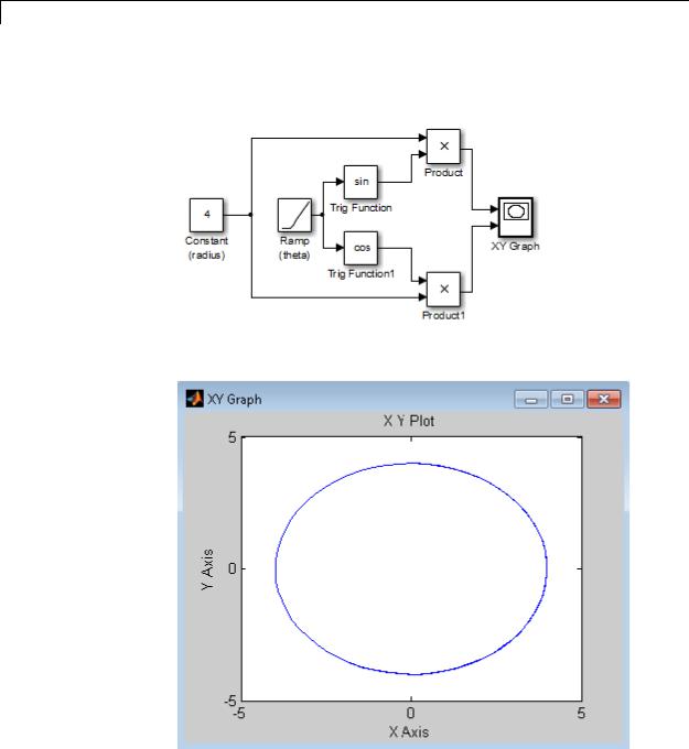
XY Graph
Examples The following model computes the points that define a circle of radius 4, centered at the origin of the x-y plane.
When you simulate the model, a figure window appears.
2-2048

XY Graph
Characteristics |
Sample Time |
Specified in the Sample time |
|
|
parameter |
|
States |
0 |
|
Zero-Crossing Detection |
No |
|
|
|
2-2049
Zero-Order Hold
Purpose |
Implement zero-order hold of one sample period |
Library Discrete
Description The Zero-Order Hold block holds its input for the sample period you specify. The block accepts one input and generates one output. Each signal can be scalar or vector. If the input is a vector, the block holds all elements of the vector for the same sample period.
You specify the time between samples with the Sample time parameter. A setting of -1 means the block inherits the Sample time.
Tip Do not use the Zero-Order Hold block to create a fast-to-slow transition between blocks operating at different sample rates. Instead, use the Rate Transition block.
Comparison |
Blocks with Similar Functionality |
|
|
||
with |
The Unit Delay, Memory, and Zero-Order Hold blocks provide similar |
|
|||
Similar |
|
||||
functionality but have different capabilities. Also, the purpose of each |
|
||||
Blocks |
block is different. The sections that follow highlight some of these |
|
|||
|
|
differences. |
|
|
|
|
|
Recommended Usage for Each Block |
|
|
|
|
|
|
|
|
|
|
|
Block |
Purpose of the Block |
Reference Examples |
|
|
|
Unit Delay |
Implement a delay using |
• sldemo_enginewc |
|
|
|
|
a discrete sample time |
(Compression |
|
|
|
|
that you specify. Ideally, |
subsystem) |
|
|
|
|
the block accepts and |
|
|
|
|
|
outputs signals with a |
|
|
|
|
|
discrete sample time. |
|
|
|
|
Memory |
Implement a delay by |
• sldemo_bounce |
|
|
|
|
one integration time step. |
• sldemo_clutch |
|
|
|
|
Ideally, the block accepts |
(Friction Mode |
|
|
|
|
|
|
|
|
|
|
|
|
|
2-2050

Zero-Order Hold
|
Block |
Purpose of the Block |
|
Reference Examples |
|
||
|
|
|
|
|
|
|
|
|
|
and outputs signals |
|
Logic/Lockup FSM |
|
||
|
|
where the sample time |
|
subsystem) |
|
||
|
|
is continuous or fixed in |
|
|
|
|
|
|
|
minor time step. For more |
|
|
|
|
|
|
|
information, see “Types |
|
|
|
|
|
|
|
of Sample Time” in the |
|
|
|
|
|
|
|
Simulink documentation. |
|
|
|
|
|
|
Zero-Order |
Convert an input signal |
|
• sldemo_radar_eml |
|
||
|
Hold |
with a continuous sample |
|
• aero_dap3dof |
|
||
|
|
time to an output signal |
|
|
|
|
|
|
|
with a discrete sample |
|
|
|
|
|
|
|
time. |
|
|
|
|
|
|
Overview of Block Capabilities |
|
|
|
|||
|
|
|
|
|
|
||
|
Capability |
|
Block |
|
|||
|
|
Unit Delay |
Memory |
|
Zero-Order |
|
|
|
|
|
|
Hold |
|
||
|
|
|
|
|
|
|
|
|
Specification |
Yes |
Yes |
|
No, because the |
|
|
|
of initial |
|
|
|
|
block output at |
|
|
condition |
|
|
|
|
time t = 0 must |
|
|
|
|
|
|
|
match the input |
|
|
|
|
|
|
|
value. |
|
|
Specification |
Yes |
No, because the |
Yes |
|
||
|
of sample |
|
block can only |
|
|
||
|
time |
|
inherit sample |
|
|
||
|
|
|
time (from the |
|
|
||
|
|
|
driving block or |
|
|
||
|
|
|
the solver used |
|
|
||
|
|
|
for the entire |
|
|
||
|
|
|
model). |
|
|
|
|
2-2051
Zero-Order Hold
|
Capability |
|
Block |
|
|
|
|
Unit Delay |
Memory |
Zero-Order |
|
|
|
|
Hold |
|
|
|
|
|
|
|
|
|
Support for |
Yes |
No |
Yes |
|
|
frame-based |
|
|
|
|
|
signals |
|
|
|
|
|
Support for |
Yes |
No |
No |
|
|
state logging |
|
|
|
|
Effect of Solver Specification on Block Output
When you specify a discrete sample time in the dialog box for a Unit Delay or Zero-Order Hold block, the block output can differ depending on the solver specification for the model.
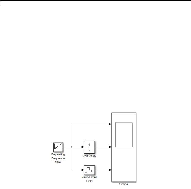
Suppose that you have a model with Unit Delay and Zero-Order Hold blocks, which both use a discrete sample time of 1:
The Repeating Sequence Stair block uses a continuous sample time of 0 to provide input signals to the Unit Delay and Zero-Order Hold blocks.
2-2052
Zero-Order Hold
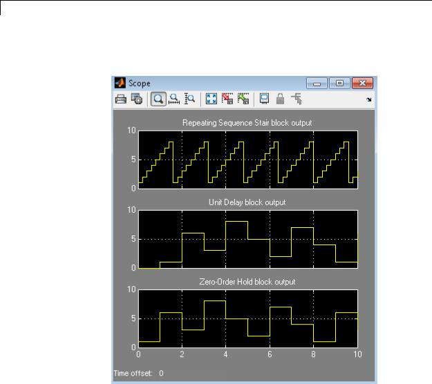
If the model uses a fixed-step solver with a step size of 1, the scope shows the following simulation results:
2-2053
Zero-Order Hold
If the model uses a variable-step solver, the scope shows the following simulation results:
The Zero-Order Hold block takes the input value of the Repeating Sequence Stair block at t = 0, 1, 2, ... , 9 and holds each input value for a sample period (1 second). The Unit Delay block applies the same 1-second hold to each input value of the Repeating Sequence Stair block, but also delays each value by a sample period. The Initial conditions
2-2054
Zero-Order Hold
Data Type
Support
Parameters and Dialog Box
parameter specifies the output for the Unit Delay block during the first sample period. For more information about sample time, see “What Is Sample Time?” and “Specify Sample Time”.
Solver specification for a model also affects the behavior of the Memory block. For details, see “Examples of Memory Block Usage” on page 2-949.
The Zero-Order Hold block accepts real or complex signals of any data type that Simulink supports, including fixed-point and enumerated data types.
For more information, see “Data Types Supported by Simulink” in the Simulink documentation.
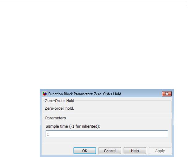
Sample time (-1 for inherited)
Specify the time interval between samples. To inherit the sample time, set this parameter to -1. See “Specify Sample Time” in the online documentation for more information.
Do not specify a continuous sample time, either 0 or [0,0]. This block supports only discrete sample times. When this parameter is -1, the inherited sample time must be discrete and not continuous.
2-2055

Zero-Order Hold
Bus |
The Zero-Order Hold block is a bus-capable block. The input can be a |
||
Support |
virtual or nonvirtual bus signal. No block-specific restrictions exist. |
||
|
|
All signals in a nonvirtual bus input to a Zero-Order Hold block must |
|
|
|
have the same sample time, even if the elements of the associated bus |
|
|
|
object specify inherited sample times. You can use a Rate Transition |
|
|
|
block to change the sample time of an individual signal, or of all signals |
|
|
|
in a bus. See “About Composite Signals” and “Bus-Capable Blocks” |
|
|
|
for more information. |
|
|
|
You can use an array of buses as an input signal to a Zero-Order Hold |
|
|
|
block. For details about defining and using an array of buses, see |
|
|
|
“Combine Buses into an Array of Buses”. |
|
Examples |
The following models show how to use the Zero-Order Hold block: |
||
|
|
• sldemo_radar_eml |
|
|
|
• aero_dap3dof |
|
Characteristics |
|
|
|
|
Bus-capable |
Yes |
|
|
|
Direct Feedthrough |
Yes |
|
|
Sample Time |
Specified in the Sample time |
|
|
|
parameter |
|
|
Scalar Expansion |
No |
|
|
Dimensionalized |
Yes |
|
|
Zero-Crossing Detection |
No |
See Also |
|
Memory, Unit Delay |
|
2-2056
Zero-Pole
Purpose |
Model system by zero-pole-gain transfer function |
Library Continuous
Description The Zero-Pole block models a system that you define with the zeros, poles, and gain of a Laplace-domain transfer function. This block can model single-input single output (SISO) and single-input multiple-output (SIMO) systems.
Conditions for Using This Block
The Zero-Pole block assumes the following conditions:
• The transfer function has the form
H(s) = K |
Z(s) |
= K |
(s − Z(1))(s − Z(2)) (s − Z(m)) |
, |
P(s) |
|
|||
|
|
(s − P(1))(s − P(2)) (s − P(n)) |
||
where Z represents the zeros, P the poles, and K the gain of the transfer function.
•The number of poles must be greater than or equal to the number of zeros.
•If the poles and zeros are complex, they must be complex-conjugate pairs.
•For a multiple-output system, all transfer functions must have the same poles. The zeros can differ in value, but the number of zeros for each transfer function must be the same.
Note You cannot use a Zero-Pole block to model a multiple-output system when the transfer functions have a differing number of zeros or a single zero each. Use multiple Zero-Pole blocks to model such systems.
2-2057

Zero-Pole
Modeling a Single-Output System
For a single-output system, the input and the output of the block are scalar time-domain signals. To model this system:
1Enter a vector for the zeros of the transfer function in the Zeros field.
2Enter a vector for the poles of the transfer function in the Poles field.
3Enter a 1-by-1 vector for the gain of the transfer function in the Gain field.
Modeling a Multiple-Output System
For a multiple-output system, the block input is a scalar and the output is a vector, where each element is an output of the system. To model this system:
1Enter a matrix of zeros in the Zeros field.
Each column of this matrix contains the zeros of a transfer function that relates the system input to one of the outputs.
2Enter a vector for the poles common to all transfer functions of the system in the Poles field.
3Enter a vector of gains in the Gain field.
Each element is the gain of the corresponding transfer function in
Zeros.
Each element of the output vector corresponds to a column in Zeros.
Transfer Function Display on the Block
The Zero-Pole block displays the transfer function depending on how you specify the zero, pole, and gain parameters.
•If you specify each parameter as an expression or a vector, the block shows the transfer function with the specified zeros, poles, and gain.
2-2058
Zero-Pole
Data Type
Support
If you specify a variable in parentheses, the block evaluates the variable.
For example, if you specify Zeros as [3,2,1], Poles as (poles), where poles is [7,5,3,1], and Gain as gain, the block looks like this:
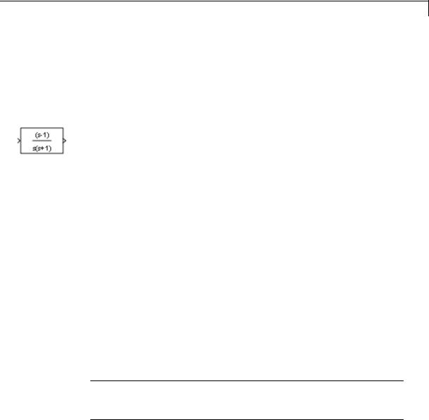
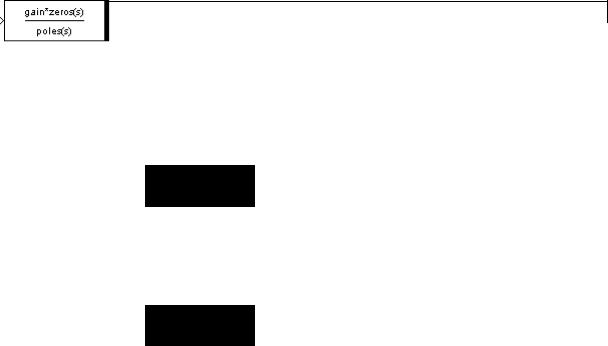
•If you specify each parameter as a variable, the block shows the variable name followed by (s) if appropriate.
For example, if you specify Zeros as zeros, Poles as poles, and Gain as gain, the block looks like this:
The Zero-Pole block accepts real signals of type double. For more information, see “Data Types Supported by Simulink” in the Simulink documentation.
2-2059
Zero-Pole
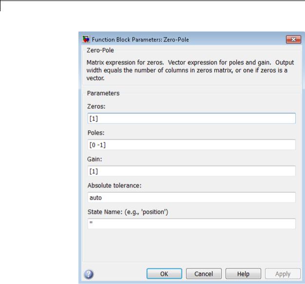
Parameters and Dialog Box
2-2060

Zero-Pole
Zeros
Define the matrix of zeros.
Settings
Default: [1]
Tips
•For a single-output system, enter a vector for the zeros of the transfer function.
•For a multiple-output system, enter a matrix. Each column of this matrix contains the zeros of a transfer function that relates the system input to one of the outputs.
Command-Line Information
See “Block-Specific Parameters” on page 8-109 for the command-line information.
2-2061

Zero-Pole
Poles
Define the vector of poles.
Settings
Default: [0 -1]
Tips
•For a single-output system, enter a vector for the poles of the transfer function.
•For a multiple-output system, enter a vector for the poles common to all transfer functions of the system.
Command-Line Information
See “Block-Specific Parameters” on page 8-109 for the command-line information.
2-2062
Zero-Pole
Gain
Define the vector of gains.
Settings
Default: [1]
Tips
•For a single-output system, enter a 1-by-1 vector for the gain of the transfer function.
•For a multiple-output system, enter a vector of gains. Each element is the gain of the corresponding transfer function in Zeros.
Command-Line Information
See “Block-Specific Parameters” on page 8-109 for the command-line information.
2-2063

Zero-Pole
Absolute tolerance
Specify the absolute tolerance for computing block states.
Settings
Default: auto
•You can enter auto, 1, a real scalar, or a real vector.
•If you enter auto or 1, then Simulink uses the absolute tolerance value in the Configuration Parameters dialog box (see “Solver Pane”) to compute block states.
•If you enter a real scalar, then that value overrides the absolute tolerance in the Configuration Parameters dialog box for computing all block states.
•If you enter a real vector, then the dimension of that vector must match the dimension of the continuous states in the block. These values override the absolute tolerance in the Configuration Parameters dialog box.
Command-Line Information
See “Block-Specific Parameters” on page 8-109 for the command-line information.
2-2064

Zero-Pole
State Name (e.g., ’position’)
Assign a unique name to each state.
Settings
Default: ' '
If this field is blank, no name assignment occurs.
Tips
•To assign a name to a single state, enter the name between quotes, for example, 'velocity'.
•To assign names to multiple states, enter a comma-delimited list surrounded by braces, for example, {'a', 'b', 'c'}. Each name must be unique.
•The state names apply only to the selected block.
•The number of states must divide evenly among the number of state names.
•You can specify fewer names than states, but you cannot specify more names than states.
For example, you can specify two names in a system with four states. The first name applies to the first two states and the second name to the last two states.
•To assign state names with a variable in the MATLAB workspace, enter the variable without quotes. A variable can be a string, cell array, or structure.
Command-Line Information
See “Block-Specific Parameters” on page 8-109 for the command-line information.
Characteristics |
Direct Feedthrough |
Only if the lengths of the Poles and |
|
|
Zeros parameters are equal |
|
Sample Time |
Continuous |
|
|
|
2-2065

Zero-Pole
|
|
Scalar Expansion |
No |
|
|
States |
Length of the Poles vector |
|
|
Dimensionalized |
No |
|
|
Zero-Crossing Detection |
No |
See Also |
|
Discrete Zero-Pole |
|
2-2066

Arduino Digital Input
Purpose |
Get logical value of digital input pin |
Library |
Target for Use with Arduino Hardware |
Description
Get the logical value of a digital pin on the Arduino hardware:
•If the logical value of the digital pin is LOW, the block outputs 0.
•If the logical value of the digital pin is HIGH, the block outputs 1.
The data type of the block output is uint8.
If you simulate your model without running it on the target hardware, this block outputs zeroes. See “Block Produces Zeros in Simulation”
Warning
Only connect digital pins to devices that use 5 Volt TTL logic.
For details, read the documentation for your Arduino hardware.
2-2067
Arduino Digital Input
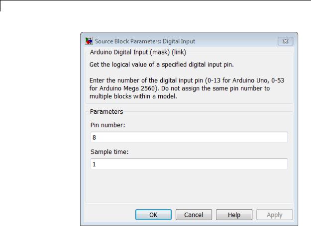
Dialog
Pin number
Enter the number of the digital pin.
Do not assign the same pin number to multiple blocks within the model.
If you set the Target hardware parameter to:
•Arduino Mega 2560, enter a pin number from 0 to 53.
•Arduino Uno, enter a pin number from 0 to 13.
2-2068

Arduino Digital Input
See Also
External
Web Sites
Note To change the Target hardware parameter, select
Tools > Run on Target Hardware > Options
Sample time
Specify how often this block reads the pin value, in seconds. Enter a value greater than zero. This value defaults to a sample time of 1 second. The minimum value is 0.000001 second.
Smaller values require the processor to complete the same number of instructions in less time, which can cause task overruns.
Arduino Digital Output | “Install Support for Arduino Hardware” | “Detect and Fix Task Overruns on Arduino Hardware” |
• http://arduino.cc/en/Reference/DigitalRead
2-2069
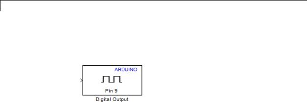
Arduino Digital Output
Purpose |
Set logical value of digital output pin |
Library |
Target for Use with Arduino Hardware |
Description
Set the logical value of a digital pin on the Arduino hardware:
•Sending 1 to the block input sets the logical value of the digital pin HIGH to 5 V or 3.3 V, depending on the board voltage.
•Sending 0 to the block input sets the logical value of the digital pin LOW to 0 V.
The block input inherits the data type of the upstream block, and internally converts it to boolean.
If you simulate your model without running it on the target hardware, this block does nothing. See “Block Produces Zeros in Simulation”.
2-2070
Arduino Digital Output
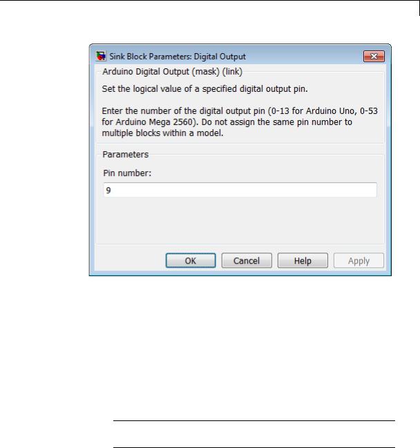
Dialog
Pin number
Enter the number of the digital pin.
Do not assign the same pin number to multiple blocks within the model.
If you set the Target hardware parameter to:
•Arduino Mega 2560, enter a pin number from 0 to 53.
•Arduino Uno, enter a pin number from 0 to 13.
Note To change the Target hardware parameter, select
Tools > Run on Target Hardware > Options
2-2071

Arduino Digital Output
See Also
External
Web Sites
Arduino Digital Input | “Install Support for Arduino Hardware” |
• http://arduino.cc/en/Reference/DigitalWrite
2-2072
Arduino Analog Input
Purpose |
Measure voltage of analog input pin |
Library |
Target for Use with Arduino Hardware |
Description
Measure the voltage of an analog pin relative to the analog input reference voltage on the Arduino hardware. Output the measurement as a 10-bit value that ranges from 0 to 1023.
•If the measured voltage equals the ground voltage, the block outputs
0.
•If the measured voltage equals the analog reference voltage, the block outputs 1023.
The default value of the analog input reference voltage is 0 to 5 V. To change the Analog input reference voltage parameter in your model Configuration Parameters, select Tools > Run on Target Hardware
> Options....
If you simulate your model without running it on the target hardware, this block outputs zeroes. See “Block Produces Zeros in Simulation”
Warning
The range of the voltage that can be applied to the analog input pin depends on the analog input reference voltage. For details, read the documentation for your Arduino hardware.
2-2073
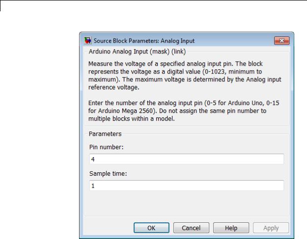
Arduino Analog Input
Dialog
Pin number
Enter the number of the analog input pin.
Do not assign the same pin number to multiple blocks within the model.
If you set the Target hardware parameter to:
• Arduino Mega 2560, enter a pin number from 0 to 15.
2-2074
Arduino Analog Input
See Also
External
Web Sites
• Arduino Uno, enter a pin number from 0 to 5.
Note To change the Target hardware parameter, select
Tools > Run on Target Hardware > Options
Sample time
Specify how often this block reads the pin value. Enter a value greater than zero. This value defaults to a sample time of 1 second. The minimum value is 0.000001 second.
Smaller values require the processor to complete the same number of instructions in less time, which can cause task overruns.
Arduino PWM | “Analog input reference voltage” | “Install Support for Arduino Hardware” | “Detect and Fix Task Overruns on Arduino Hardware” |
•http://arduino.cc/en/Reference/AnalogRead
•http://arduino.cc/en/Reference/AnalogReference
2-2075
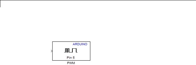
Arduino PWM
Purpose |
Generate PWM waveform on analog output pin |
Library |
Target for Use with Arduino Hardware |
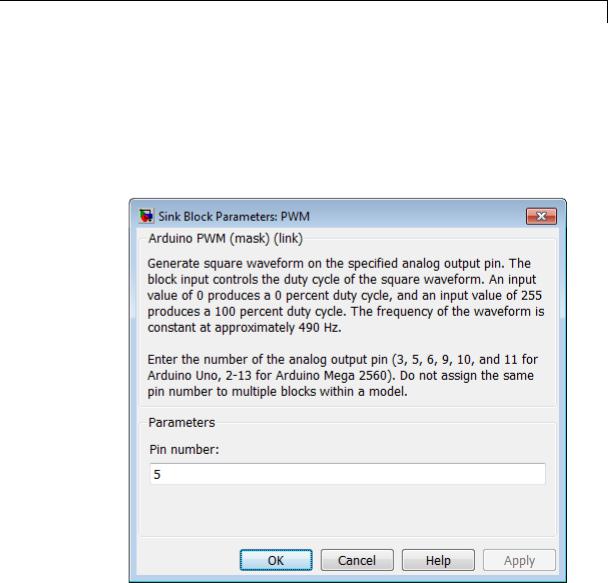
Description
Use pulse-width modulation (PWM) to change the duty-cycle of square-wave pulses output by a PWM pin on the Arduino hardware. PWM enables a digital output to provide a range of different power levels, similar to that of an analog output.
The value sent to the block input determines the width of the square wave, called duty-cycle, that the target hardware outputs on the specified PWM pin. The range of valid outputs is 0 to 255.
For example:
•Sending the maximum value, 255, to the block input produces 100% duty-cycle, which results in full power on a PWM pin.
•Sending the minimum value, 0, to the block input produces 0% duty-cycle, which results in no power on a PWM pin.
•Sending an intermediate value to the block input produces a proportional duty-cycle and power output on a PWM pin. For example, sending 192 to the block input produces 75% duty cycle and power (192/256 = 0.75).
•Sending out-of-range values, such as 500 or -500, to the block input has the same effect as sending the maximum or minimum input values.
The frequency of the square wave is ~490 Hz.
The block input inherits the data type of the upstream block, and internally converts it to uint8.
2-2076
Arduino PWM
Some limitations:
•With Arduino Uno hardware, the Arduino PWM block cannot use digital pins 9 or 10 when the model contains Servo blocks.
•With Arduino Mega 2560 hardware, the Arduino PWM block cannot use digital pins 11 or 12 when the model contains more than 12 Servo blocks.
Dialog
Pin number
Enter the number of the PWM pin.
2-2077

Arduino PWM
See Also
External
Web Sites
Do not assign the same pin number to multiple blocks within the model.
If you set the Target hardware parameter to:
•Arduino Mega 2560, enter a pin number from 2 to 13.
•Arduino Uno, enter one of the following pin numbers: 3, 5, 6, 9, 10, and 11. The board identifies these with a ~ symbol.
Note To change the Target hardware parameter, select
Tools > Run on Target Hardware > Options
“Install Support for Arduino Hardware” |
• http://arduino.cc/en/Reference/AnalogWrite
2-2078
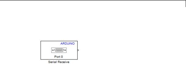
Arduino Serial Receive
Purpose |
Get one byte of data from serial port |
Library |
Target for Use with Arduino Hardware |
Description
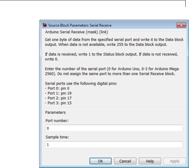
Get one byte of data per sample period from the receive buffer of the specified serial port. For more information, see “Use Serial Communications with Arduino Hardware”.
The Serial Receive block has two block outputs, Data and Status. When data is available:
•The Data block output emits data from the serial receive buffer.
•The Status block output emits 1.
When data is not available:
•The Data block output emits 255.
•The Status block output emits 0.
The datatype of the Data block output is uint8.
The datatype of the Status block output is int. You can use the Status block output to determine whether a value of 255 emitted by the Data block output is data, or an indication that no data was received.
If you simulate your model without running it on the target hardware, this block outputs zeroes. See “Block Produces Zeros in Simulation”
If you use this block in models with the Standard Servo Read, Standard Servo Write, and Continuous Servo Write blocks, use longer sample times to avoid overruns.
2-2079

Arduino Serial Receive
Warning
Only connect serial port pins to devices that use 5 Volt TTL logic. Do not connect these pins to an RS-232 serial interface, such as the DE-9M connector on a computer, without limiting the voltage. The RS-232 standard allows higher voltages that can damage your hardware. For details, read the documentation for your Arduino hardware.
2-2080
Arduino Serial Receive
Dialog
Port Number
Enter the number of the serial port.
If you set the Target hardware parameter to:
• Arduino Mega 2560, enter a port number from 0 to 3.
2-2081
Arduino Serial Receive
See Also
External
Web Sites
• Arduino Uno, enter 0.
Note To change the Target hardware parameter, select
Tools > Run on Target Hardware > Options
You can assign a Serial Transmit block and a Serial Receive block to the same serial port.
Do not assign more than one Serial Receive block to the same serial port.
Do not assign the pin numbers used by the serial port to other blocks within the model.
Serial port 0 is connected to the USB port through a converter. Do not use both serial port 0 and the USB port at the same time. For example, do not use serial port 0 if you intend to use External mode, because External mode requires the USB port.
Sample time
Specify how often this block reads the serial port buffer. Enter a value greater than zero. This value defaults to a sample time of 1 second. The minimum value is 0.000001 second.
Smaller values require the processor to complete the same number of instructions in less time, which can cause task overruns.
Arduino Serial Transmit | “Install Support for Arduino Hardware” | “Use Serial Communications with Arduino Hardware” | “Tune and Monitor Models Running on Arduino Mega 2560 Hardware” | “Detect and Fix Task Overruns on Arduino Hardware” |
• http://arduino.cc/en/Serial/Read
2-2082
Arduino Serial Transmit
Purpose |
Send buffered data to serial port |
Library |
Target for Use with Arduino Hardware |
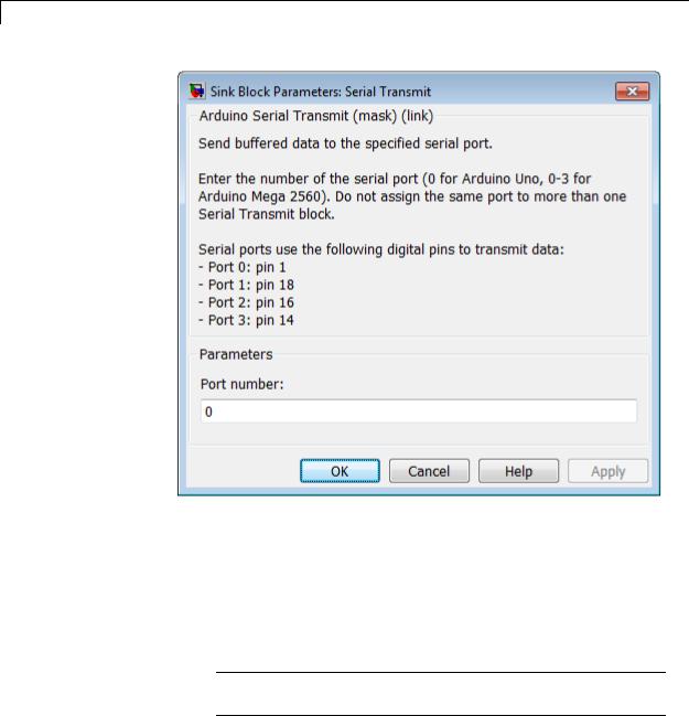
Description
Send buffered data to the specified serial port. For more information, see “Use Serial Communications with Arduino Hardware”.
The Arduino Uno hardware has one serial port device, serial port 0, connected to the digital pins marked TX 1 and RX 0. If you set the Port number parameter to 0, this block transmits over the digital pin marked TX 1.
The block input accepts vector or scalar uint8 data. To convert a data source to uint8, use a Data Type Conversion block.
If you simulate your model without running it on the target hardware, this block does nothing. See “Block Produces Zeros in Simulation”.
If you use this block in models with the Standard Servo Read, Standard Servo Write, and Continuous Servo Write blocks, use longer sample times to avoid overruns.
Warning
Only connect serial port pins to devices that use 5 Volt TTL logic. Do not connect these pins to an RS-232 serial interface, such as the DE-9M connector on a computer, without limiting the voltage. The RS-232 standard allows higher voltages that can damage your hardware. For details, read the documentation for your Arduino hardware.
2-2083
Arduino Serial Transmit
Dialog
Port Number
Enter the number of the serial port.
If you set the Target hardware parameter to:
•Arduino Mega 2560, enter a port number from 0 to 3.
•Arduino Uno, enter 0.
Note To change the Target hardware parameter, select
Tools > Run on Target Hardware > Options
2-2084

Arduino Serial Transmit
See Also
External
Web Sites
You can assign a Serial Transmit block and a Serial Receive block to the same serial port.
Do not assign multiple Serial Transmit blocks to the same serial port.
Do not assign the pin numbers used by the serial port to other blocks within the model.
Serial port 0 is connected to the USB port through a converter. Do not use both serial port 0 and the USB port at the same time. For example, do not use serial port 0 if you intend to use External mode, because External mode requires the USB port.
Arduino Serial Receive | “Install Support for Arduino Hardware” | “Use Serial Communications with Arduino Hardware” | “Tune and Monitor Models Running on Arduino Mega 2560 Hardware” |
• http://arduino.cc/en/Serial/Write
2-2085

Arduino Standard Servo Read
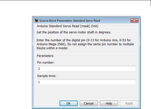
Purpose |
Get position of standard servo motor shaft in degrees |
Library |
Target for Use with Arduino Hardware |
Description
Measure the angle of a standard servo motor shaft in degrees, from 0 to 180.
The data type of the block output is uint8.
If you simulate your model without running it on the target hardware, this block outputs zeroes. See “Block Produces Zeros in Simulation”.
Some limitations:
•Do not use Servo blocks with External mode.
•If you use this block in models with the Serial Receive and Serial Transmit blocks, use longer sample times to avoid overruns.
•The maximum number of Servo blocks per model is 12 for Arduino Uno hardware, and 48 for Arduino Mega 2560 hardware.
•With Arduino Uno hardware, the Arduino PWM block cannot use digital pins 9 or 10 when the model contains Servo blocks.
•With Arduino Mega 2560 hardware, the Arduino PWM block cannot use digital pins 11 or 12 when the model contains more than 12 Servo blocks.
2-2086
Arduino Standard Servo Read
Dialog
Pin number
Enter the number of the digital pin.
Do not assign the same pin number to multiple blocks within the model.
If you set the Target hardware parameter to:
•Arduino Mega 2560, enter a pin number from 0 to 53.
•Arduino Uno, enter a pin number from 0 to 13.
2-2087
Arduino Standard Servo Read
See Also
External
Web Sites
Note To change the Target hardware parameter, select
Tools > Run on Target Hardware > Options
Sample time
Specify how often this block reads the pin value. Enter a value greater than zero. This value defaults to a sample time of 1 seconds. The minimum value is 0.000001 second.
Smaller values require the processor to complete the same number of instructions in less time, which can cause task overruns.
Arduino Standard Servo Write | Arduino Continuous Servo Write | “Install Support for Arduino Hardware” | “Detect and Fix Task Overruns on Arduino Hardware” |
• http://arduino.cc/en/Reference/ServoRead
2-2088
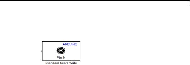
Arduino Standard Servo Write
Purpose |
Set shaft position of standard servo motor |
Library |
Target for Use with Arduino Hardware |
Description
Set the shaft position of a standard servo motor, from 0 to 180 degrees.
To rotate the servo shaft, send values from 0 to 180 to the block input.
Sending out-of-range values, such as -5 or 200, to the block input has the same effect as sending the maximum or minimum input values.
The block input inherits the data type of the upstream block, and internally converts it to uint8.
If you simulate your model without running it on the target hardware, this block does nothing. See “Block Produces Zeros in Simulation”.
Some limitations:
•Do not use Servo blocks with External mode.
•If you use this block in models with the Serial Receive and Serial Transmit blocks, use longer sample times to avoid overruns.
•The maximum number of Servo blocks per model is 12 for Arduino Uno hardware, and 48 for Arduino Mega 2560 hardware.
•With Arduino Uno hardware, the Arduino PWM block cannot use digital pins 9 or 10 when the model contains Servo blocks.
•With Arduino Mega 2560 hardware, the Arduino PWM block cannot use digital pins 11 or 12 when the model contains more than 12 Servo blocks.
2-2089
Arduino Standard Servo Write
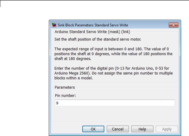
Dialog
Pin number
Enter the number of the digital pin.
Do not assign the same pin number to multiple blocks within the model.
If you set the Target hardware parameter to:
•Arduino Mega 2560, enter a pin number from 0 to 53.
•Arduino Uno, enter a pin number from 0 to 13.
2-2090
Arduino Standard Servo Write
See Also
External
Web Sites
Note To change the Target hardware parameter, select
Tools > Run on Target Hardware > Options
Arduino Standard Servo Read | Arduino Continuous Servo Write | “Install Support for Arduino Hardware” |
• http://arduino.cc/en/Reference/ServoWrite
2-2091
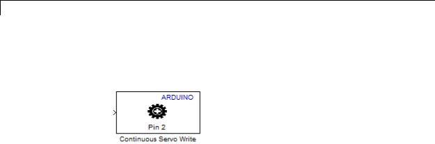
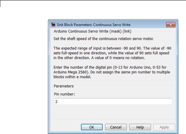
Arduino Continuous Servo Write
Purpose |
Set shaft speed of continuous rotation servo motor |
Library |
Target for Use with Arduino Hardware |
Description
Set the direction and speed of a continuous rotation servo motor:
•Sending -90 to the block input produces the maximum rate of rotation in one direction.
•Sending 90 to the block input produces the maximum rate of rotation in the opposite direction.
•Sending 0 to the block input stops the servo motor.
•Sending out-of-range values, such as -95 or 200, to the block input has the same effect as sending the maximum or minimum input values.
The characteristics of some motors cause them to continue rotating when the block input value is 0. In that case, you can experiment to find an offset value that stops the motor.
With Arduino Mega 2560 hardware, you can use External mode to determine the offset while your model is running on the hardware. See “Tune and Monitor Models Running on Arduino Mega 2560 Hardware”.
The block input inherits the data type of the upstream block, and internally converts it to uint8.
If you simulate your model without running it on the target hardware, this block does nothing. See “Block Produces Zeros in Simulation”.
Some limitations:
2-2092
Arduino Continuous Servo Write
•Do not use Servo blocks with External mode.
•If you use this block in models with the Serial Receive and Serial Transmit blocks, use longer sample times to avoid overruns.
•The maximum number of Servo blocks per model is 12 for Arduino Uno hardware, and 48 for Arduino Mega 2560 hardware.
•With Arduino Uno hardware, the Arduino PWM block cannot use digital pins 9 or 10 when the model contains Servo blocks.
•With Arduino Mega 2560 hardware, the Arduino PWM block cannot use digital pins 11 or 12 when the model contains more than 12 Servo blocks.
2-2093
Arduino Continuous Servo Write
Dialog
Pin number
Enter the number of the digital pin.
Do not assign the same pin number to multiple blocks within the model.
If you set the Target hardware parameter to:
•Arduino Mega 2560, enter a pin number from 0 to 53.
•Arduino Uno, enter a pin number from 0 to 13.
2-2094

Arduino Continuous Servo Write
See Also
External
Web Sites
Note To change the Target hardware parameter, select
Tools > Run on Target Hardware > Options
Arduino Standard Servo Read | Arduino Standard Servo Write | “Install Support for Arduino Hardware” |
• http://arduino.cc/en/Reference/ServoWrite
2-2095

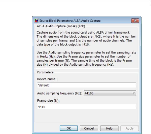
BeagleBoard ALSA Audio Capture
Purpose |
Capture audio from sound card using ALSA |
Library |
Target for Use with BeagleBoard Hardware |
|
Target for Use with PandaBoard Hardware |
Description
Capture the left and right audio channels from the AUDIO IN connector or a stereo sound device using the Advanced Linux Sound Architecture (ALSA) driver framework. The block output, Out, emits an N-by-2 frame of int16 values. The width of the frame, 2, corresponds to the left and right audio channels. To determine the sample rate of the block output, divide the Frame size (N) by the Audio sampling frequency (Hz). For example, if Frame size (N) is 4410 and Audio sampling frequency (Hz) is 44100, then the sample rate is 0.1 seconds.
2-2096
PandaBoard ALSA Audio Capture
Dialog
Device name
Use the default ALSA device, or specify an audio input device by name.
To use the default sound device specified by the ALSA configuration file, leave this parameter set to 'default'.
2-2097

PandaBoard ALSA Audio Capture
To find out which sound device the ALSA configuration file specifies, connect to the board and open the
/usr/share/alsa/alsa.conf file. In the following example, the alsa.conf file specifies device 2 on card 0 as the default device:
pcm.!default { type hw
card 0 device 2
}
To specify an audio input device by name, connect to the board and open the /proc/asound/cards file. In the following example, the cards file names two devices, VirMIDI and AudioPCI:
$ cat /proc/asound/cards 0 [Dummy ]: Dummy - Dummy Dummy 1
1 [VirMIDI ]: VirMIDI - VirMIDI Virtual MIDI Card 1
2 [AudioPCI ]: ENS1371 - Ensoniq AudioPCI Ensoniq AudioPCI ENS1371 at 0xe400, irq 11
This parameter value defaults to 'default'.
Audio sampling frequency (Hz)
Enter the sampling frequency of the ALSA Audio Capture (input) device.
By default, the sampling frequency of ALSA Audio Capture is the same as the sampling frequency of ALSA Audio Playback.
This parameter value defaults to 44100 Hz (44.1 kHz). The maximum rate equals the sampling rate of the audio capture device.
2-2098

PandaBoard ALSA Audio Capture
See Also
External
Web Sites
Frame size (N)
Enter the number of samples this block will output to your model. This parameter value defaults to 4410.
PandaBoard ALSA Audio Playback | “Connect to Serial Port on BeagleBoard Hardware” | “Install Support for BeagleBoard Hardware”
|
•http://www.alsa-project.org
•http://en.wikipedia.org/wiki/Advanced_Linux_Sound_Architecture
•http://beagleboard.org/
2-2099

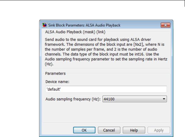
BeagleBoard ALSA Audio Playback
Purpose |
Send audio to sound card for playback using ALSA |
Library |
Target for Use with BeagleBoard Hardware |
|
Target for Use with PandaBoard Hardware |
Description
Send audio to the sound card for playback using the Advanced Linux Sound Architecture (ALSA) driver framework. The dimensions of the block input, In, are N-by-2, where N is the number of samples per frame, and 2 is the number of audio channels. The data type of the block input must be int16. Use the Audio sampling frequency parameter to set the sampling rate in Hertz (Hz).
Note When you use the software volume controls to lower the volume of one channel, crosstalk from the other channel may be audible.
2-2100
PandaBoard ALSA Audio Playback
Dialog
Device name
Use the default ALSA device, or specify an audio input device by name.
To use the default sound device specified by the ALSA configuration file, leave this parameter set to 'default'.
To find out which sound device the ALSA configuration file specifies, connect to the board and open the
/usr/share/alsa/alsa.conf file. In the following example, the alsa.conf file specifies device 2 on card 0 as the default device:
2-2101

PandaBoard ALSA Audio Playback
pcm.!default { type hw
card 0 device 2
}
To specify an audio input device by name, connect to the board and open the /proc/asound/cards file. In the following example, the cards file names two devices, VirMIDI and AudioPCI:
$ cat /proc/asound/cards 0 [Dummy ]: Dummy - Dummy Dummy 1
1 [VirMIDI ]: VirMIDI - VirMIDI Virtual MIDI Card 1
2 [AudioPCI ]: ENS1371 - Ensoniq AudioPCI Ensoniq AudioPCI ENS1371 at 0xe400, irq 11
This parameter value defaults to 'default'.
Audio sampling frequency (Hz)
Enter the sample frequency of the ALSA Audio Playback (output) device.
By default, the sample frequency of ALSA Audio Playback is the same as the sample frequency of ALSA Audio Capture.
This parameter value defaults to 44100 Hz (44.1 kHz). The maximum rate equals the sampling rate of the audio capture device.
See Also PandaBoard ALSA Audio Capture | “Connect to Serial Port on BeagleBoard Hardware” | “Install Support for BeagleBoard Hardware”
|
2-2102
PandaBoard ALSA Audio Playback
External
Web Sites
•http://www.alsa-project.org
•http://en.wikipedia.org/wiki/Advanced_Linux_Sound_Architecture
•http://beagleboard.org/
•http://pandaboard.org/
2-2103
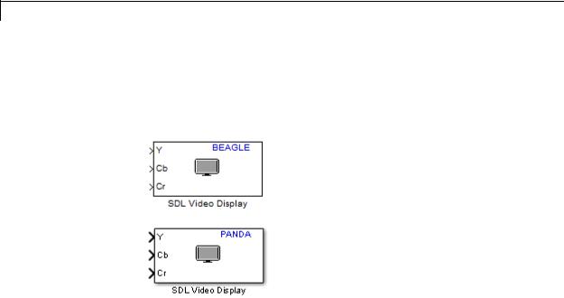
BeagleBoard SDL Video Display
Purpose |
Display video using SDL |
Library |
Target for Use with BeagleBoard Hardware |
|
Target for Use with PandaBoard Hardware |
Description
Display video data using the Simple Directmedia Layer (SDL) multimedia library. A Simulink model can contain only one SDL Video Display block.
This block takes planar or interleaved video data in YCbCr 4:2:2 or RGB formats.
2-2104
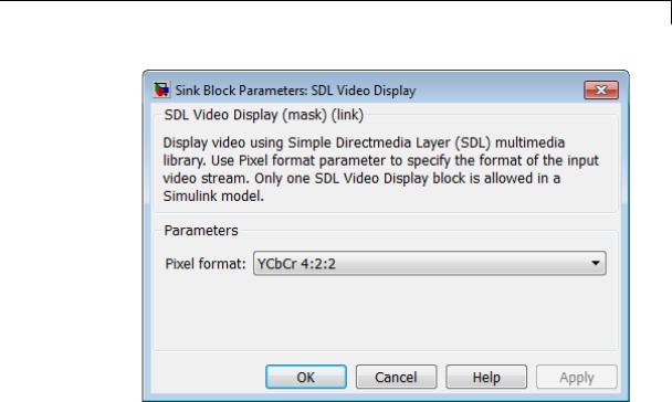
PandaBoard SDL Video Display
Dialog
Pixel format
Specify the format of the input video stream: YCbCr 4:2:2 or RGB.
YCbCr 4:2:2 uses three channels to represent color image data for each pixel:
•Y is the luma component (essentially a grayscale signal).
•Cb is the blue-difference chroma component.
•Cr is the red-difference chroma component.
Cb and Cr are sampled at half the rate of Y. Therefore, if the dimensions of Y are M*N, the dimensions of Cb and Cr are each (M/2) by N.
RGB uses three 8-bit values to represent the red, green, and blue components of each pixel.
2-2105

PandaBoard SDL Video Display
See Also
External
Web Sites
This parameter value defaults to YCbCr 4:2:2.
PandaBoard V4L2 Video Capture | “Install Support for BeagleBoard Hardware” |
•http://en.wikipedia.org/wiki/Chroma_subsampling
•http://beagleboard.org/
•http://pandaboard.org/
•https://groups.google.com/forum/#!topic/beagleboard/x8MT086mKe0
•http://processors.wiki.ti.com/index.php/Beagle_Board_Challenge:_TurtleCam
2-2106
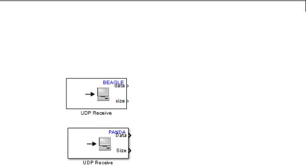
BeagleBoard UDP Receive
Purpose |
Receive UDP packets over IP network |
Library |
Target for Use with BeagleBoard Hardware |
|
Target for Use with PandaBoard Hardware |
Description
Receive UDP packets from the local network. The block output, data, emits UDP packet data as a one-dimensional vector of a specified data type. The block output, size, emits the size the data in the UDP buffer.
While UDP Receive waits for new data to arrive, size emits a stream of zeros. When new data arrives, size changes to a non-zero value.
If you simulate a model that contains the UDP Receive block on your host computer (e.g., Simulation > Normal), and send UDP packets to that model from a board, the data output emits a disproportionately large number of zeros. This is because Simulink software simulates the model as a free-running application with a shorter period than the real-time application running on the board. In other words, the free-running simulation outputs zeros because it is waiting for the “slower” real-time application on the board to send data. If both applications were running on boards, this mismatch would not occur.
2-2107
PandaBoard UDP Receive
Note If you are having trouble using UDP to communicate with a computer, investigate whether antivirus or firewall software might be blocking UDP traffic. If so, try reconfiguring the software to allow UDP traffic for a specific IP port number.
2-2108

PandaBoard UDP Receive
Dialog
Local IP port
The number of the IP port on the local device, which can range from 1 to 65535. This value defaults to 25000. The “local device” is the board running the model.
2-2109

PandaBoard UDP Receive
See Also
External
Web Sites
Data type
Set the data type of the vector elements in the Message output. Match the data type with the data input used to create the UDP packets. This option defaults to uint8.
Data size (elements)
Set the number of data elements in each UDP packet. Match the data size used to create the UDP packets. This value defaults to 255 elements.
Sample time (seconds)
Specify how often this block reads the port buffer. Enter a value greater than zero. This value defaults to a sample time of 0.01 seconds.
Smaller values require the processor to complete the same number of instructions in less time, which can cause task overruns.
PandaBoard UDP Send | “Install Support for BeagleBoard Hardware” | “Detect and Fix Task Overruns on BeagleBoard Hardware” |
•http://en.wikipedia.org/wiki/User_Datagram_Protocol
•http://beagleboard.org/
•http://pandaboard.org/
2-2110
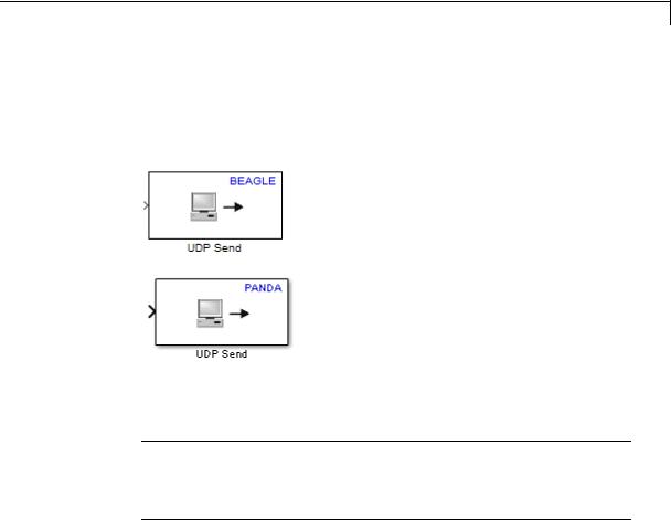
BeagleBoard UDP Send
Purpose |
Send UDP packets over IP network |
Library |
Target for Use with BeagleBoard Hardware |
|
Target for Use with PandaBoard Hardware |
Description
Send a UDP packet to a network address identified by the remote IP address and remote IP port parameters.
Note If you are having trouble using UDP to communicate with a computer, investigate whether antivirus or firewall software might be blocking UDP traffic. If so, try reconfiguring the software to allow UDP traffic for a specific IP port number.
2-2111
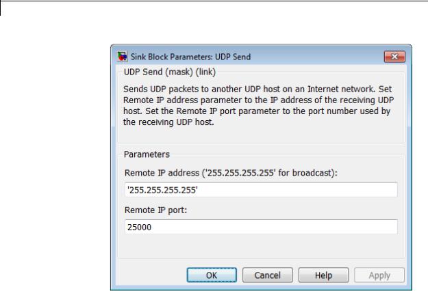
PandaBoard UDP Send
Dialog
Remote IP address (‘255.255.255.255’ for broadcast)
The address or hostname of the IP node on the remote device. To broadcast the UDP message to all remote devices, keep the default parameter value, '255.255.255.255'.
Remote IP port
The number of the IP port on the remote device, which can range from 1 to 65535. This value defaults to 25000.
See Also PandaBoard UDP Receive | “Install Support for BeagleBoard Hardware” |
2-2112
PandaBoard UDP Send
Related
Examples
External
Web Sites
•Get the IP Address of the BeagleBoard Hardware
•http://en.wikipedia.org/wiki/User_Datagram_Protocol
•http://beagleboard.org/
•http://pandaboard.org/
2-2113
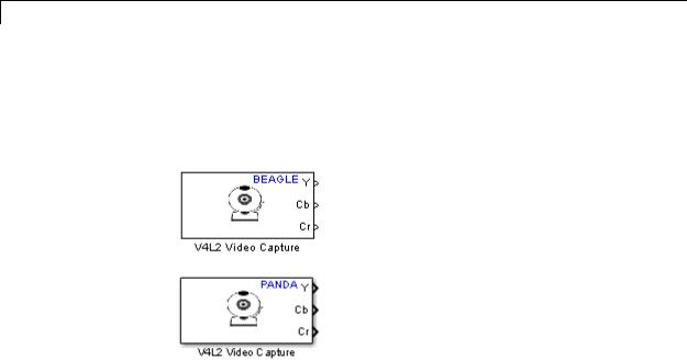
BeagleBoard V4L2 Video Capture
Purpose |
Capture video from USB camera using V4L2 |
Library |
Target for Use with BeagleBoard Hardware |
|
Target for Use with PandaBoard Hardware |
Description
Capture live video from a USB video camera, using the V4L2 (Video for Linux Two API) driver framework. The output is in row major format. During simulation, the model outputs a moving colorbar image.
The Ubuntu Linux image used on the target hardware supports video capture from USB cameras listed as Universal Video Class (UVC). In addition to being a UVC class camera, the camera itself must support data acquisition in YUYV mode.
The following cameras have been tested:
•Logitech QuickCam Pro 9000
•Logitech QuickCam Pro 3000
•Logitech Webcam C600
•Logitech HD Webcam C310
For a list of Logitech webcams that support UVC, see
http://logitech-en-amr.custhelp.com/app/answers/detail/a_id/6471.
2-2114

PandaBoard V4L2 Video Capture
For a list of UVC cameras supported by Ubuntu, see http://www.ideasonboard.org/uvc/.
For BeagleBoard hardware only: If you connect any USB camera to a USB Host port on the board, the video output contains artifacts that look like small dark scratches. This is a known hardware issue, and is independent of the Linux distribution. To work around this issue, connect the camera to the BeagleBoard’s USB OTG port using a “Micro USB OTG to USB 2.0 Adapter”. The USB OTG port is labelled “OTG” and is located next to the BeagleBoard’s “5V” or “5VDC” connector. This issue is discussed at:
•http://processors.wiki.ti.com/index.php/Beagle_Board_Challenge:_TurtleCam
•https://groups.google.com/forum/#!topic/beagleboard/x8MT086mKe0
2-2115
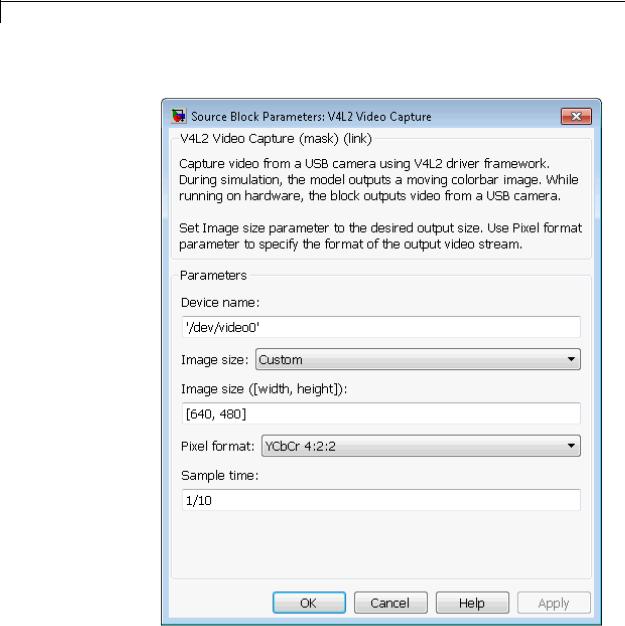
PandaBoard V4L2 Video Capture
Dialog |
Device Configuration |
2-2116

PandaBoard V4L2 Video Capture
Device name
Enter the path and name of the video device. This parameter value defaults to '/dev/video0'.
The Linux kernel creates a video device file when you connect a supported USB video camera to the board. By default, the Linux kernel supports all USB video class (UVC) devices.
To see the list of video device files, open a command line session with the board and enter: ls -al /dev/video*.
Image size ([width, height])
Specify the width in pixels and height in lines of the image to capture.
This parameter value defaults to [640, 480].
Pixel format
Select the video format of the video device, RGB or YCbCr 4:2:2.
RGB represents the red, green, and blue components of a pixel using an 8-bit value. RGB color space is device-dependent.
YCbCr 4:2:2 uses three channels to represent color image data for each pixel:
•Y is the luma component (essentially a grayscale signal).
•Cb is the blue-difference chroma component.
•Cr is the red-difference chroma component.
The Cb and Cr components are sampled at half the sample rate of Y. See http://en.wikipedia.org/wiki/Chroma_subsampling.
This parameter value defaults to YCbCr 4:2:2.
Sample time
Select the sample time of the video device. This parameter value defaults to 1/10
2-2117

PandaBoard V4L2 Video Capture
See Also
External
Web Sites
Smaller values require the processor to complete the same number of instructions in less time, which can cause task overruns.
PandaBoard SDL Video Display | “Install Support for BeagleBoard Hardware” | “Detect and Fix Task Overruns on BeagleBoard Hardware” |
•http://en.wikipedia.org/wiki/Chroma_subsampling
•http://logitech-en-amr.custhelp.com/app/answers/detail/a_id/6471
•http://www.ideasonboard.org/uvc/
•http://beagleboard.org/
•http://pandaboard.org/
•http://processors.wiki.ti.com/index.php/Beagle_Board_Challenge:_TurtleCam
•https://groups.google.com/forum/#!topic/beagleboard/x8MT086mKe0
2-2118

LEGO MINDSTORMS NXT Acceleration Sensor
Purpose |
Measure acceleration along three axes |
Library |
Target for Use with LEGO MINDSTORMS NXT Hardware |
Description
Measure the linear acceleration along the X, Y, and Z axes of the NAC1040 HiTechnic NXT Acceleration / Tilt Sensor.
The axes of the sensor are oriented as shown here.
For each axis, the sensor measures -2 g to +2 g of acceleration. The sensor outputs approximately 200 counts per g.
Note The SI equivalent of 1 g is 9.8 meters per second squared.
You can use this sensor to:
2-2119
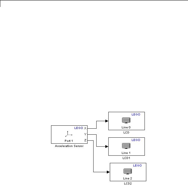
LEGO MINDSTORMS NXT Acceleration Sensor
•Determine the orientation of the sensor, for example in a self-levelling robot.
•Measure small and moderate acceleration forces, such as road surface vibration and acceleration in a vehicle.
•Detect larger acceleration events, such as a collision.
If you simulate your model without running it on the target hardware, this block outputs zeroes. See “Block Produces Zeros in Simulation”.
Use the Acceleration Sensor
View the changing outputs of an acceleration sensor as you change the orientation of the sensor.
Open the legonxtlib block library and copy the blocks shown to a new model.
Connect the Acceleration Sensor block to the LCD blocks, as shown.
Double click each LCD block to open the block masks for each block.
2-2120
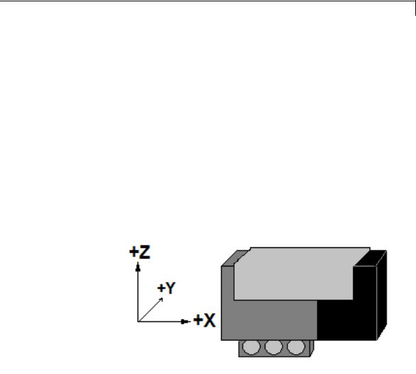
LEGO MINDSTORMS NXT Acceleration Sensor
Use the Display at line parameters to select a different line number for each block.
Use the Display label parameters to add an X, Y, or Z label for each line.
Connect the Acceleration sensor to Port 1 on the NXT brick.
Prepare and run the model on the NXT brick.
Move the Acceleration sensor about and observe the outputs on the LCD.
Position the Acceleration sensor on a table and systematically change the orientation of the sensor. The horizontal axes, such as X and Y in the following illustration, output values near zero. The vertical axis, such as Z in the following illustration, measures Earth’s gravitational acceleration and therefore outputs a value near 200. If you invert the Z axis from the position shown, the sensor outputs a value near -200.
2-2121
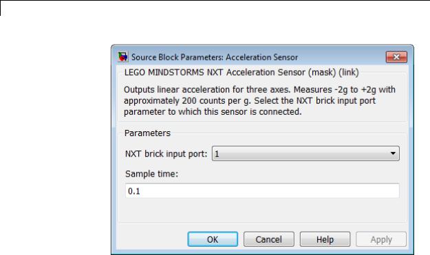
LEGO MINDSTORMS NXT Acceleration Sensor
Dialog
Box
See Also
External
Web Sites
NXT brick input port
Select the NXT sensor port to which the sensor is connected. Avoid assigning multiple devices to the same port. The options are 1, 2, 3, or 4.
Sample time
Specify how often the block reads sensor values.
Smaller values require the processor to complete the same number of instructions in less time, which can cause task overruns.
“Install Support for LEGO MINDSTORMS NXT Hardware” | “Detect and Fix Task Overruns on NXT Brick” |
• HiTechnic NXT Acceleration / Tilt Sensor (NAC1040)
2-2122
LEGO MINDSTORMS NXT Battery
Purpose |
Measure voltage of battery in NXT brick |
Library |
Target for Use with LEGO MINDSTORMS NXT Hardware |
Description
This block measures the voltage of the battery located in the NXT brick, and outputs the value in millivolts. For example, when the six 1.5 volt batteries are fully charged, the output value is approximately 9000.
If you simulate your model without running it on the target hardware, this block outputs zeroes. See “Block Produces Zeros in Simulation”.
Measure Battery Voltage
Measure the voltage of the batteries in the NXT brick.
Open the legonxtlib block library and copy the blocks shown to a new model.
Connect the Battery block to the LCD block, as shown.
Prepare and run the model on the NXT brick.
Observe the battery voltage, shown in millivolts, on the LCD display.
2-2123
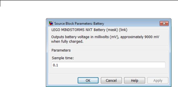
LEGO MINDSTORMS NXT Battery
Dialog
Box
See Also
External
Web Sites
Sample time
Specify how often the block reads battery values.
Smaller values require the processor to complete the same number of instructions in less time, which can cause task overruns.
LEGO MINDSTORMS NXT Battery | LEGO MINDSTORMS NXT Button | LEGO MINDSTORMS NXT LCD | LEGO MINDSTORMS NXT Speaker | LEGO MINDSTORMS NXT Timer | “Install Support for LEGO MINDSTORMS NXT Hardware” | “Detect and Fix Task Overruns on NXT Brick” |
• http://mindstorms.lego.com
2-2124
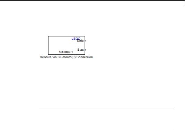
LEGO MINDSTORMS NXT Receive via Bluetooth Connection
Purpose |
Receive data from another NXT brick over Bluetooth |
Library |
Target for Use with LEGO MINDSTORMS NXT Hardware |
Description
Receive data from another NXT brick over the built-in Bluetooth device. The model running on the other NXT brick must contain a Send via Bluetooth Connection block.
To establish multiple channels between the two NXT bricks, use multiple pairs of Bluetooth blocks, and set the Mailbox parameters for each pair to a unique number. This approach cannot be used to establish communication between more than two NXT bricks.
Note Because External mode relies on a Bluetooth connection between the host computer and the NXT brick, you cannot use External mode with models that contain a Send via Bluetooth Connection block or a Receive via Bluetooth Connection block.
2-2125
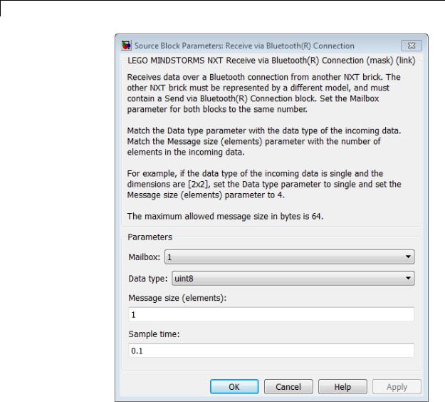
LEGO MINDSTORMS NXT Receive via Bluetooth Connection
Dialog
Box
Mailbox
Set the Mailbox parameter in both the Send via Bluetooth
Connection and Receive via Bluetooth Connection blocks to the
same number.
2-2126

LEGO MINDSTORMS NXT Receive via Bluetooth Connection
See Also
Related
Examples
External
Web Sites
Data type
Match the Data type parameter with the data type of the incoming data.
Message size (elements)
Match the Message size (elements) parameter with the number of elements in the incoming data. For example, if the data type of the incoming data is single and the dimensions are [2x2], set the Message size (elements) parameter to single and set the
Message size (elements) to 4.
Sample time
Specify how often the block reads buffer values.
Smaller values require the processor to complete the same number of instructions in less time, which can cause task overruns.
LEGO MINDSTORMS NXT Send via Bluetooth Connection | “Install Support for LEGO MINDSTORMS NXT Hardware” | “Detect and Fix Task Overruns on NXT Brick” |
•“Exchange Data Between Two NXT Bricks”
•http://mindstorms.lego.com
2-2127
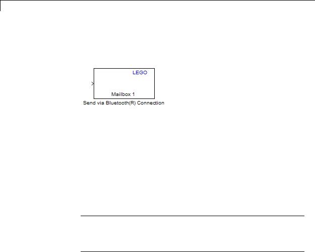
LEGO MINDSTORMS NXT Send via Bluetooth Connection
Purpose |
Send data to another NXT brick over Bluetooth |
Library |
Target for Use with LEGO MINDSTORMS NXT Hardware |
Description
Send data to another NXT brick over the built-in Bluetooth device. The model running on the other NXT brick must contain a Receive via Bluetooth Connection block.
To establish multiple channels between the two NXT bricks, use multiple pairs of Bluetooth blocks, and set the Mailbox parameters for each pair to a unique number. This approach cannot be used to establish communication between more than two NXT bricks.
The maximum size for the block input is 64 bytes. The supported data types for the block input are uint8, int8, uint16, int16, uint32, int32, single, and double.
Note Because External mode relies on a Bluetooth connection between the host computer and the NXT brick, you cannot use External mode with models that contain a Send via Bluetooth Connection block or a Receive via Bluetooth Connection block.
2-2128
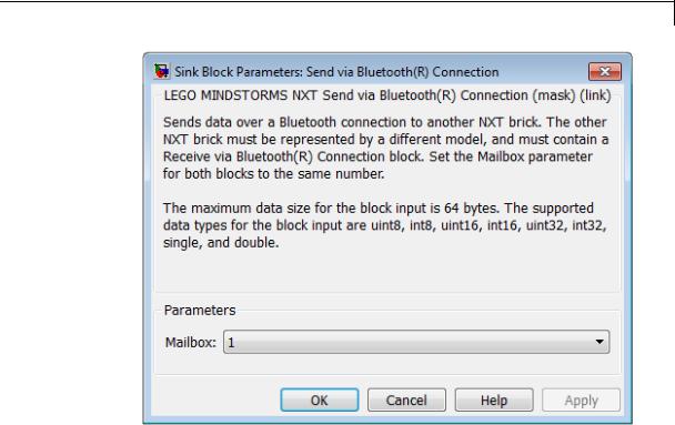
LEGO MINDSTORMS NXT Send via Bluetooth Connection
Dialog
Box
See Also
Related
Examples
External
Web Sites
Mailbox
Set the Mailbox parameter in both the Send via Bluetooth Connection and Receive via Bluetooth Connection blocks to the same number.
LEGO MINDSTORMS NXT Receive via Bluetooth Connection | “Install Support for LEGO MINDSTORMS NXT Hardware” |
•“Exchange Data Between Two NXT Bricks”
•http://mindstorms.lego.com
2-2129
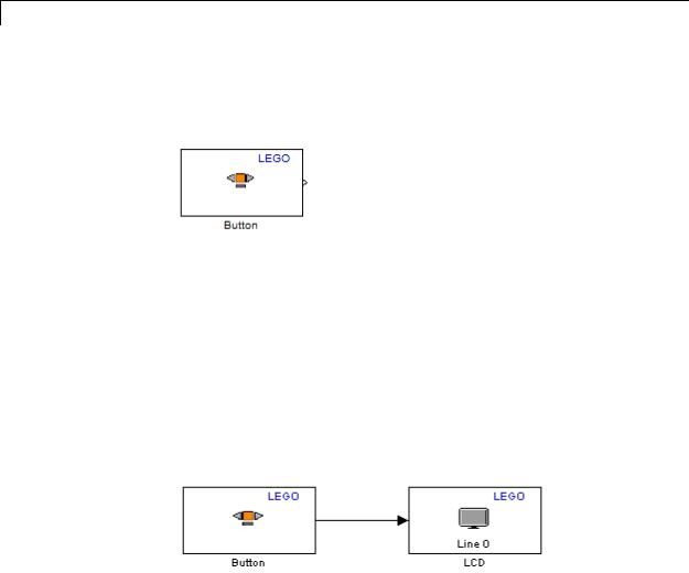
LEGO MINDSTORMS NXT Button
Purpose |
Output state of button on NXT brick |
Library |
Target for Use with LEGO MINDSTORMS NXT Hardware |
Description
Get the state of the “middle orange” or “right arrow” button on the NXT brick: 1 while pressed and 0 while released.
If you simulate your model without running it on the target hardware, this block outputs zeroes. See “Block Produces Zeros in Simulation”.
Use the Button
Measure the voltage of the batteries in the NXT brick.
Open the legonxtlib block library and copy the blocks shown to a new model.
Connect the Button block to the LCD block, as shown.
Prepare and run the model on the NXT brick.
Press the orange button on the NXT brick, and observe 0 on the LCD display turn to 1.
2-2130
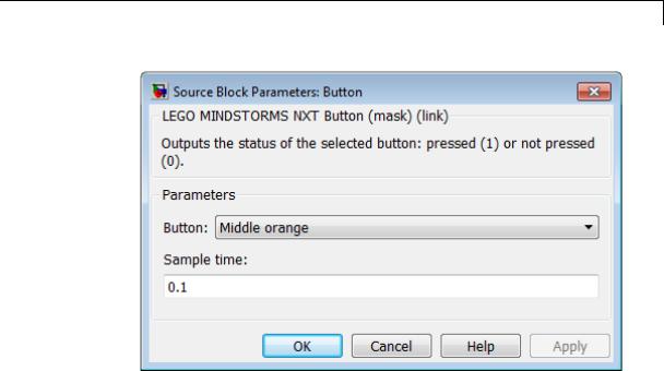
LEGO MINDSTORMS NXT Button
Dialog
Box
See Also
External
Web Sites
Button
Select the button for which to output status. The options are
Middle orange and Right arrow.
Sample time
Specify how often the block reads the state of the button.
Smaller values require the processor to complete the same number of instructions in less time, which can cause task overruns.
LEGO MINDSTORMS NXT Battery | LEGO MINDSTORMS NXT Button | LEGO MINDSTORMS NXT LCD | LEGO MINDSTORMS NXT Speaker | LEGO MINDSTORMS NXT Timer | “Install Support for LEGO MINDSTORMS NXT Hardware” | “Detect and Fix Task Overruns on NXT Brick” |
• http://mindstorms.lego.com
2-2131

LEGO MINDSTORMS NXT Color Sensor
Purpose |
Measure color or light intensity |
Library |
Target for Use with LEGO MINDSTORMS NXT Hardware |
Description
Measure color, or light intensity (luminance) from the LEGO 10286 Color Sensor. The sensor measures color using separate red, green, and blue (RGB) components.
If you simulate your model without running it on the target hardware, this block outputs zeroes. See “Block Produces Zeros in Simulation”.
Use the Color Sensor
Use the Color Sensor block to measure the color or light intensity of an object.
Open the legonxtlib block library and copy the blocks shown to a new model.
2-2132
LEGO MINDSTORMS NXT Color Sensor
Connect the Color Sensor block to the LCD blocks.
Double click each LCD block to open the block masks for each block.
Use the Display at line parameters to select a different line number for each block.
Use the Display label parameters to add an R, G, or B label for each line.
Connect the color sensor to Port 1 on the NXT brick.
Prepare and run the model on the NXT brick.
Point the color sensor at a variety of well-lit colored objects and observe the measured red, green, and blue components of that color on the LCD. When you point the sensor at a bright white light, all three output values are near 255. When you point the sensor at a dark shadow, all three output values are low, nearer to 0.
In the Color Sensor block, change the Sensor type parameter to Light. This action changes the block output for the red component, R, into an unlabeled block output for light measurements.
2-2133

LEGO MINDSTORMS NXT Color Sensor
Delete the broken connectors and unused LCD blocks from the model, and then run the model on the NXT brick.
Point the color sensor at a variety of well-lit colored objects and observe the light measurements. When you point the sensor at a bright white light, the block output values are high, near 90. When you point the sensor at a dark shadow, all three output values are low, near 6.
2-2134
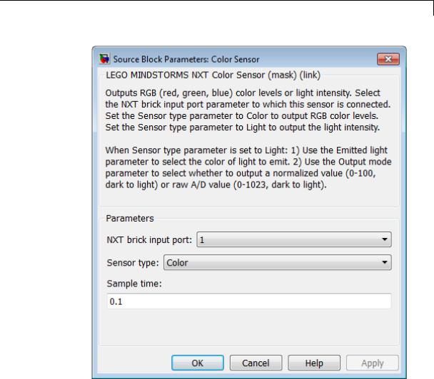
LEGO MINDSTORMS NXT Color Sensor
Dialog
Box
NXT brick input port
Select the NXT sensor port to which the sensor is connected. Avoid assigning multiple devices to the same port. The options are 1, 2, 3, or 4.
2-2135

LEGO MINDSTORMS NXT Color Sensor
Sensor type
Select the type of measurement to perform, Color (the default) or
Light.
When you select Color, the block outputs a 1-by-3 matrix of RGB values. Each value ranges from 0 (darkest) to 255 (brightest).
When you select Light, the block displays two new parameters,
Emitted light and Output mode.
Emitted light
This parameter is only available when the Sensor type parameter is set to Light.
Use Emitted light to choose the color of light the LED on the sensor emits, or to turn the LED off. The options are Red, Green,
Blue, White, and None.
Output mode
This parameter is only available when the Sensor type parameter is set to Light.
Select the range the block outputs, Normalized (0-100) or Raw A/D (0-1023).
When you select Normalized (0-100), the block outputs light intensity as normalized values that range from 0 (darkest) to 100 (brightest).
When you select Raw A/D (0-1023), the block outputs light intensity as raw values that ranges from 0 (darkest) to 1023 (brightest).
Sample time
Specify how often the block reads sensor values.
Smaller values require the processor to complete the same number of instructions in less time, which can cause task overruns.
2-2136

LEGO MINDSTORMS NXT Color Sensor
See Also
External
Web Sites
LEGO MINDSTORMS NXT Light Sensor | “Install Support for LEGO MINDSTORMS NXT Hardware” | “Detect and Fix Task Overruns on NXT Brick” |
• http://mindstorms.lego.com
2-2137
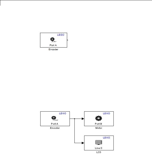
LEGO MINDSTORMS NXT Encoder
Purpose |
Measure encoder rotation from NXT Interactive Servo Motor |
Library |
Target for Use with LEGO MINDSTORMS NXT Hardware |
Description
This block uses the encoder in the LEGO 9842 Interactive Servo Motor to measure the rotation of the wheel in degrees. Driving the wheel forward increments the measurement, and driving the wheel in reverse decrements the measurement.
If you simulate your model without running it on the target hardware, this block outputs zeroes. See “Block Produces Zeros in Simulation”.
Use the Encoder
Use the Encoder block to measure encoder rotation from an NXT
Interactive Servo Motor
Open the legonxtlib block library and copy the blocks shown to a new model.
2-2138

LEGO MINDSTORMS NXT Encoder
Connect the Encoder block to the Motor block and the LCD block, as shown.
Double click the Motor block to open the block mask, and change the
NXT brick output port parameter to B.
Connect one servo motor to Port A on the NXT brick. Connect another servo motor to Port B on the NXT brick.
Prepare and run the model on the NXT brick.
Slowly rotate the wheel of servo motor connected to Port A in each direction. Observe the servo motor connected to Port B drive in one direction and then in the other direction as you input positive or negative values. Using the input value displayed on the LCD, observe that values larger than 100 or -100 do not increase the motor speed.
In the Encoder block, experiment with changing the Reset mode parameter to Reset at each sample time, and changing the Sample time parameter to 1.
Run the model on the NXT brick again.
Observe that the block output values remain lower and reset to zero every second.
2-2139
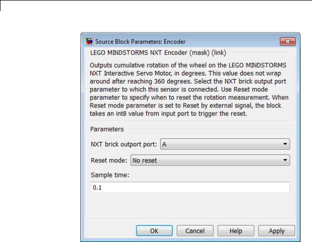
LEGO MINDSTORMS NXT Encoder
Dialog
Box
NXT brick output port
Select the NXT brick output port to which the encoder is connected. The options are A, B, or C.
The LEGO 9842 Interactive Servo Motor contains both a motor and an encoder. If your model uses a Motor block and an Encoder block for the same LEGO 9842 Interactive Servo Motor, set the NXT brick output port parameter in both of those blocks to the same port.
2-2140

LEGO MINDSTORMS NXT Encoder
See Also
External
Web Sites
Reset mode
Choose whether to reset the measurement value:
•No reset — Do not reset the measurement value. Measure the total degrees of rotation.
•Reset at each sample time — For each sample period, output the measurement value and then reset it to 0.
•Reset by external signal — Create a block input that can reset the measurement value to 0. When you send a value other than 0 to the block input, reset the measurement value to 0. For each sample period, output the measurement value since the last reset.
Sample time
Specify how often the block reads sensor values.
Smaller values require the processor to complete the same number of instructions in less time, which can cause task overruns.
LEGO MINDSTORMS NXT Motor | “Install Support for LEGO MINDSTORMS NXT Hardware” | “Detect and Fix Task Overruns on NXT Brick” |
• http://mindstorms.lego.com
2-2141
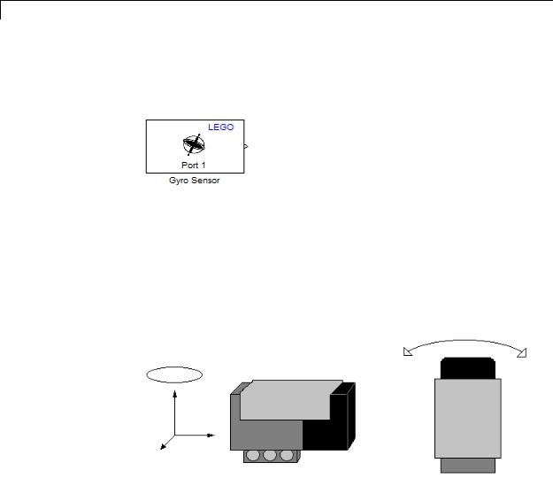
LEGO MINDSTORMS NXT Gyro Sensor
Purpose |
Measure rate of rotation |
Library |
Target for Use with LEGO MINDSTORMS NXT Hardware |
Description
This block measures rate of rotation (yaw) along the a single axis of the HiTechnic NXT Gyro Sensor (NGY1044). This yaw is indicated by a circle above the vertical axis in the image on the left, and by a double-arrow in the image on the right.
Before using this sensor for precise measurements, use the offset value to remove small positive or negative bias in the output values, as described in the example below.
If you simulate your model without running it on the target hardware, this block outputs zeroes. See “Block Produces Zeros in Simulation”.
Calibrate the Gyro Sensor
Use the Gyro Sensor block to perform zero-calibration for the gyro sensor
2-2142
LEGO MINDSTORMS NXT Gyro Sensor
Open the legonxtlib block library and copy the blocks shown to a new model.
Connect the Gyro Sensor block to the LCD block, as shown.
Connect the NXT Gyro Sensor to the NTX brick.
Prepare and run the model on the NXT brick.
Observe any bias in the measurement values from the Gyro sensor visible on the LCD display of the NXT brick.
Double-click the Gyro Sensor block. In the block mask that opens, increase or decrease the offset value to reduce the bias.
Save the changes to your model and run the model again. Repeat these last two steps until the bias is nearly zero.
2-2143

LEGO MINDSTORMS NXT Gyro Sensor
Dialog
Box
NXT brick input port
Select the NXT sensor port to which the sensor is connected. Avoid assigning multiple devices to the same port. The options are 1, 2, 3, or 4.
Output mode
Select the type of rotation data to output:
2-2144

LEGO MINDSTORMS NXT Gyro Sensor
See Also
External
Web Sites
Rotation rate (-360 - 360) outputs the rate of rotation in degrees per second. When this option is selected, the block displays the Offset parameter.
Raw A/D (0 - 1023) outputs the rate of rotation in raw analog-to-digital values per second. When this option is selected, the block hides the Offset parameter.
Sample time
Specify how often the block reads sensor values.
Smaller values require the processor to complete the same number of instructions in less time, which can cause task overruns.
LEGO MINDSTORMS NXT Acceleration Sensor | “Install Support for LEGO MINDSTORMS NXT Hardware” | “Detect and Fix Task Overruns on NXT Brick” |
• HiTechnic NXT Gyro Sensor (NGY1044)
2-2145
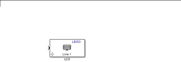
LEGO MINDSTORMS NXT LCD
Purpose |
Display number on single line of NXT LCD screen |
Library |
Target for Use with LEGO MINDSTORMS NXT Hardware |
Description
This block displays the value of the block input on the LCD located on the NXT brick. This block lets you enter a label for the value, and select the line of the LCD upon which to display the label/value.
If the value displayed changes faster than the refresh rate of the LCD, the displayed values may be blurry and hard to read.
If the model running on the NXT brick does not use the LCD, the LCD displays a default message that it is running a program.
Avoid configuring other LCD blocks to display information on the same line number.
This block automatically converts the data type of the data it receives. You do not need to perform data-type conversion on the input signals.
If you simulate your model without running it on the target hardware, this block does nothing. See “Block Produces Zeros in Simulation”.
Use the LCD Display
Use the LCD block to display a number on a single line of the LCD display on the NXT brick
Open the legonxtlib block library and copy the blocks shown to a new model.
2-2146
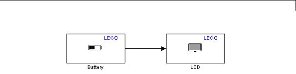
LEGO MINDSTORMS NXT LCD
Connect the Battery block to the LCD block, as shown.
Prepare and run the model on the NXT brick.
Observe the battery voltage, shown in millivolts, on line 1 of the LCD display.
Double-click the LCD block in your model.
In the block mask that opens, set the Display label parameter to Mv and the Display at line parameter to 3.
Run the model again. On the NXT brick, observe the new label and position of the battery output on the LCD screen.
2-2147
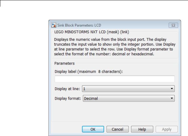
LEGO MINDSTORMS NXT LCD
Dialog
Box
Display label (maximum 8 characters)
Enter a prefix or label for the input to display. the LCD displays the prefix to the left of the input value. The prefix cannot be longer than 8 characters. For example, if you are displaying the state of the Button block, enter Button:.
Display at line
Select the line upon which to display the number. Line 1 is at the top of the LCD. Line 8 is at the bottom.
2-2148

LEGO MINDSTORMS NXT LCD
See Also
External
Web Sites
Display format
Select the format of the number. The options are Decimal or Hex (hexadecimal).
LEGO MINDSTORMS NXT Battery | LEGO MINDSTORMS NXT Button | LEGO MINDSTORMS NXT LCD | LEGO MINDSTORMS NXT Speaker | LEGO MINDSTORMS NXT Timer | “Install Support for LEGO MINDSTORMS NXT Hardware” |
• http://mindstorms.lego.com
2-2149

LEGO MINDSTORMS NXT Light Sensor
Purpose |
Measure light intensity |
Library |
Target for Use with LEGO MINDSTORMS NXT Hardware |
Description
This block outputs the intensity of light detected by the NXT Light Sensor. The sensor includes an illuminating LED to actively measure the reflectance of nearby surfaces. For example, the light-intensity under a desk measures approximately 20 while a the light-intensity of fluorescent light is approximately 85.
If you simulate your model without running it on the target hardware, this block outputs zeroes. See “Block Produces Zeros in Simulation”.
Use the Light Sensor
1Open the legonxtlib block library and copy the blocks shown to a new model.
2Connect the Light Sensor block to the LCD block, as shown.
3Connect the Light sensor to Port 1 on the NXT brick.
4Prepare and run the model on the NXT brick.
5Point the Light sensor at a variety of well-lit objects and observe the measurement on the LCD.
2-2150

LEGO MINDSTORMS NXT Light Sensor
When you point the sensor at a bright light, the measurement value is higher.
When you point the sensor at a dark shadow, the measurement value is lower.
6Hold the Light sensor near a piece of white paper in a dark location, such as under your desk. The red LED in the sensor illuminates the paper. Observe the measurements on the LCD.
When you hold the sensor nearer to the paper, the measurement value is higher.
When you hold the sensor further away from the paper, the measurement value is lower.
2-2151
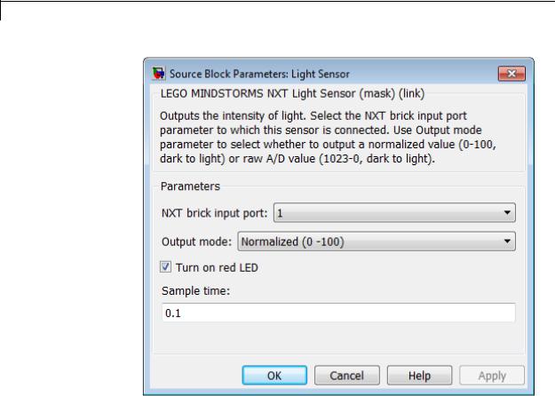
LEGO MINDSTORMS NXT Light Sensor
Dialog
Box
NXT brick input port
Select the NXT sensor port to which the sensor is connected. Avoid assigning multiple devices to the same port. The options are 1, 2, 3, or 4.
Output mode
Select the type of light intensity data to output:
Light intensity (0 - 100) outputs the intensity of the light on a scale from 0 to 100. 0 is the weakest intensity. 100 is the strongest intensity.
2-2152
LEGO MINDSTORMS NXT Light Sensor
See Also
External
Web Sites
Raw A/D (1023 - 0) outputs the intensity of the light on a scale from 1023 to 0. 1023 is the weakest intensity. 0 is the strongest intensity.
Turn on red LED
Emit red light from the LED located next to the light sensor. Under low light conditions, the sensor can use this capability to measure the amount of red light nearby objects reflect.
Sample time
Specify how often the block reads sensor values.
Smaller values require the processor to complete the same number of instructions in less time, which can cause task overruns.
LEGO MINDSTORMS NXT Color Sensor | “Install Support for LEGO MINDSTORMS NXT Hardware” | “Detect and Fix Task Overruns on NXT Brick” |
• http://mindstorms.lego.com
2-2153
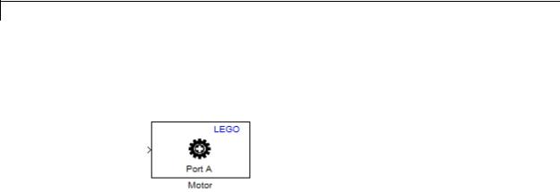
LEGO MINDSTORMS NXT Motor
Purpose |
Set motor speed and stopping action |
Library |
Target for Use with LEGO MINDSTORMS NXT Hardware |
Description
This blocks controls the speed, direction, and stopping action of the LEGO 9842 Interactive Servo Motor.
You can use this block with the LEGO MINDSTORMS NXT Encoder block, which outputs the rotation of the servo motor.
The Motor block input value controls the motor speed and direction.
•Forward: 1 to 100 (slowest to fastest)
•Reverse: –1 to –100 (slowest to fastest)
•Stop: 0
Using the Stop action parameter in the block, you can configure the motor to coast or brake when it receives an input of 0 (stop). As a side effect, when you change Stop action from Brake to Coast, the servo motor requires higher block input values to start moving and to maintain speed. The following graph shows this relationship.
2-2154
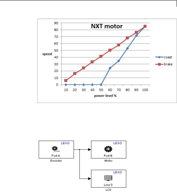
LEGO MINDSTORMS NXT Motor
This block automatically converts the data type of the data it receives. You do not need to perform data-type conversion on the input signals.
If you simulate your model without running it on the target hardware, this block does nothing. See “Block Produces Zeros in Simulation”.
Use the Motor
2-2155

LEGO MINDSTORMS NXT Motor
1Open the legonxtlib block library and copy the blocks shown to a new model.
2Connect the Encoder block to the Motor block and the LCD block, as shown.
3Double click the Motor block to open the block mask, and change the
NXT brick output port parameter to B.
4Connect one servo motor to Port A on the NXT brick. Connect another servo motor to Port B on the NXT brick.
5Prepare and run the model on the NXT brick.
6Slowly rotate the wheel of servo motor connected to Port A in each direction. Observe the servo motor connected to Port B drive in one direction and then in the other direction as you input positive or negative values. Using the input value displayed on the LCD, observe that values larger than 100 or -100 do not increase the motor speed.
7In the Motor block, experiment with changing the Stop action parameter to Coast.
Run the model on the NXT brick again.
Observe that the motor requires higher block input values both to start and to achieve the same speed as when the Stop action parameter was set to Brake.
2-2156

LEGO MINDSTORMS NXT Motor
Dialog
Box
NXT brick output port
Select the NXT brick output port to which the encoder is connected. The options are A, B, or C.
The LEGO 9842 Interactive Servo Motor contains both a motor and an encoder. If your model uses a Motor block and an Encoder block for the same LEGO 9842 Interactive Servo Motor, configure the NXT brick output port parameter in both of those blocks to use the same NXT brick output port.
Stop action
Select the stopping behavior of the motor:
•Coast stops the motor gradually through loss of momentum. When Stop action is set to coast, getting the motor to start
2-2157

LEGO MINDSTORMS NXT Motor
See Also
External
Web Sites
and run requires higher values at the block input than when
Stop action is brake.
• Brake stops the motor immediately.
LEGO MINDSTORMS NXT Encoder | “Install Support for LEGO MINDSTORMS NXT Hardware” |
• http://mindstorms.lego.com
2-2158
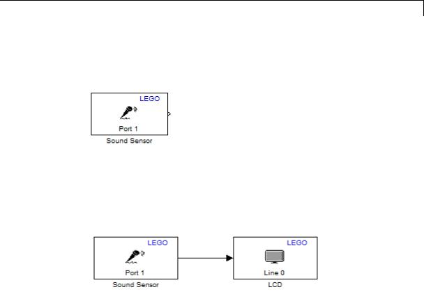
LEGO MINDSTORMS NXT Sound Sensor
Purpose |
Measure sound level |
Library |
Target for Use with LEGO MINDSTORMS NXT Hardware |
Description
Measure sound level using the LEGO MINDSTORMS NXT Sound Sensor.
If you simulate your model without running it on the target hardware, this block outputs zeroes. See “Block Produces Zeros in Simulation”.
Use the Sound Sensor
1Open the legonxtlib block library and copy the blocks shown to a new model.
2Connect the Sound block to the LCD block, as shown.
3Prepare and run the model on the NXT brick.
4While making sounds close to the sensor, and observe the sound levels shown on the LCD display.
2-2159

LEGO MINDSTORMS NXT Sound Sensor
Dialog
Box
NXT brick input port
Select the NXT sensor port to which the sensor is connected. Avoid assigning multiple devices to the same port. The options are 1, 2, 3, or 4.
Output mode
Select the type of data to output:
Sound level (0 - 100) outputs the intensity of the sound on a scale from 0 to 100. 0 is the weakest intensity. 100 is the strongest intensity.
2-2160

LEGO MINDSTORMS NXT Sound Sensor
See Also
External
Web Sites
Raw A/D (1023 - 0) outputs the intensity of the sound on a scale from 1023 to 0. 1023 is the weakest intensity. 0 is the strongest intensity.
Sample time
Specify how often the block reads sensor values.
Smaller values require the processor to complete the same number of instructions in less time, which can cause task overruns.
“Install Support for LEGO MINDSTORMS NXT Hardware” | “Detect and Fix Task Overruns on NXT Brick” |
• http://mindstorms.lego.com
2-2161
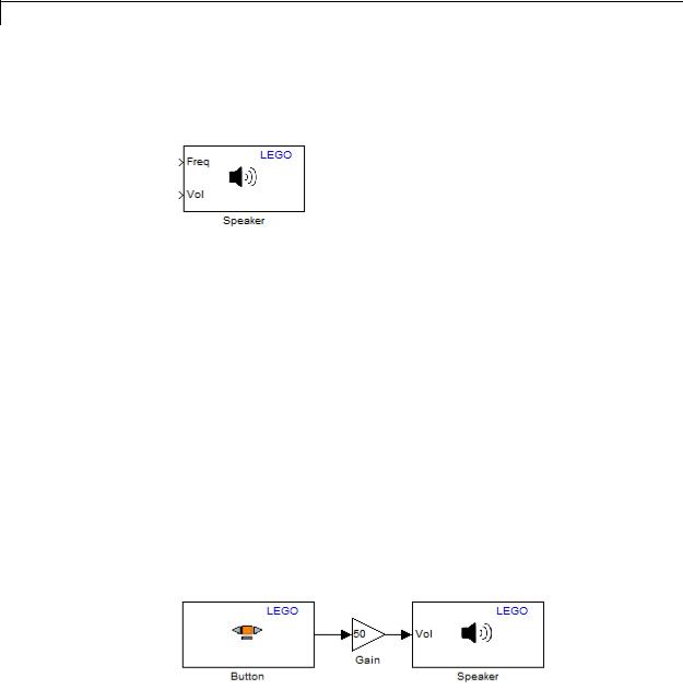
LEGO MINDSTORMS NXT Speaker
Purpose
Library
Description
Play tones on speaker in NXT brick
Target for Use with LEGO MINDSTORMS NXT Hardware
Use this block to play tones from the speaker in the NXT brick.
To play a tone, send an audible value to the block input for frequency (Freq) and/or volume (Vol). To stop playing a tone, send an inaudible value, such as zero, to either block input. The range of audible frequencies that the speaker can produce is approximately 32 to 13000 Hz. The speaker volume ranges from 0 to 100 (softest to loudest).
To set either the frequency or volume to a static value, disable one of the block inputs using the Input mode parameter, and then enter the static value for the equivalent parameter on the block mask. For example, if the speaker is only going to play a single frequency, set Input mode to Volume only, and then set the Frequency (Hz) parameter to 440.
This block automatically converts the data type of the data it receives. You do not need to perform data-type conversion on the input signals.
If you simulate your model without running it on the target hardware, this block does nothing. See “Block Produces Zeros in Simulation”.
Use the Speaker
2-2162
LEGO MINDSTORMS NXT Speaker
1Open the legonxtlib block library and copy the blocks shown to a new model.
2Double click the Speaker block. In the block mask that opens, change the Input mode parameter to Volume only, and enter a value of 440 for the Frequency (Hz) parameter. Then click OK.
3Connect the Button block to the Gain block, and the Gain block to the Speaker block, as shown.
4Double click the Gain block. In the block mask that opens, set the Gain parameter to 50. When you press the orange button on the NXT brick, the Gain block will send a value of 50 to the volume input on the Speaker block.
5Prepare and run the model on the NXT brick.
6When you press the orange button, the speaker emits a 440 Hz tone.
2-2163
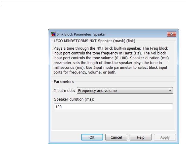
LEGO MINDSTORMS NXT Speaker
Dialog Box
2-2164
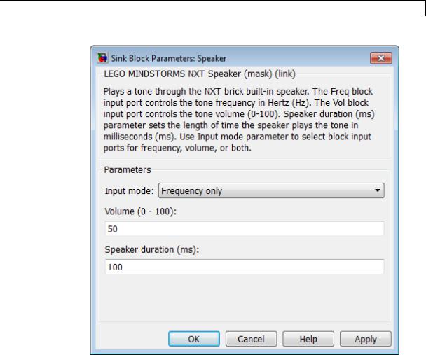
LEGO MINDSTORMS NXT Speaker
2-2165
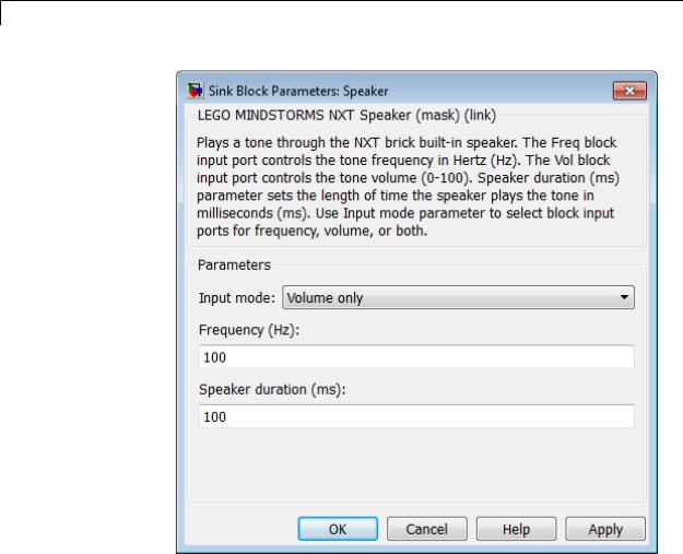
LEGO MINDSTORMS NXT Speaker
Input mode
Enable or disable the block inputs:
•Frequency and volume — Enables both Freq and Vol.
•Volume only — Enables the Vol block input, disables the Freq block input, and enables the Frequency (Hz) parameter on the block mask.
2-2166

LEGO MINDSTORMS NXT Speaker
See Also
External
Web Sites
•Frequency only — Enables the Freq block input, disables the Vol block input, and enables the Volume (0 - 100) parameter on the block mask.
Frequency (Hz)
Enter the frequency of the tone the speaker emits. When the Input mode parameter is configured to enable a Freq input, this parameter is not available.
Volume (0 - 100)
Set the volume of the tone the speaker emits. When the Input mode parameter is configured to enable a Vol input, this parameter is not available.
Speaker duration (ms)
Play a continuous tone or an intermittent tone (beeps). If this value is equal to or greater than the sample time of the source block, the speaker emits a continuous tone. If this value is shorter than the sample time of the source block, the speaker emits an intermittent tone at each sample period. For example, in the preceding ex_battery_voltage_alarm model, if the sample time for the battery is 0.1 seconds, and the speaker duration is 100 milliseconds (0.1 seconds), the speaker plays a continuous tone. If you change the speaker duration to 50 milliseconds (half the battery sample time), the speaker emits a beep every 0.1 seconds.
LEGO MINDSTORMS NXT Battery | LEGO MINDSTORMS NXT Button | LEGO MINDSTORMS NXT LCD | LEGO MINDSTORMS NXT Speaker | LEGO MINDSTORMS NXT Timer | “Install Support for LEGO MINDSTORMS NXT Hardware” |
• http://mindstorms.lego.com
2-2167
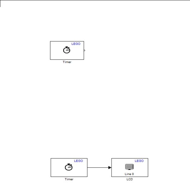
LEGO MINDSTORMS NXT Timer
Purpose |
Measure elapsed time from timer in NXT brick |
Library |
Target for Use with LEGO MINDSTORMS NXT Hardware |
Description
Measure the elapsed time, in milliseconds, from the time the NXT brick starts running the model.
With External mode disabled, the default setting, the NXT brick starts running the model when you press the right-arrow button on the NXT brick. With External mode enabled, the NXT brick automatically starts running the model when Simulink finishes downloading the model to the NXT brick.
You can see when the NXT brick starts running a model by observing the LCD on the NXT brick. For models that do not use an LCD block, the LCD on the NXT brick displays “I am running ...” followed by the model name. For models that use an LCD block, the model displays whatever output is sent to it.
If you simulate your model without running it on the target hardware, this block outputs zeroes. See “Block Produces Zeros in Simulation”.
Use the Timer
1Open the legonxtlib block library and copy the blocks shown to a new model.
2-2168
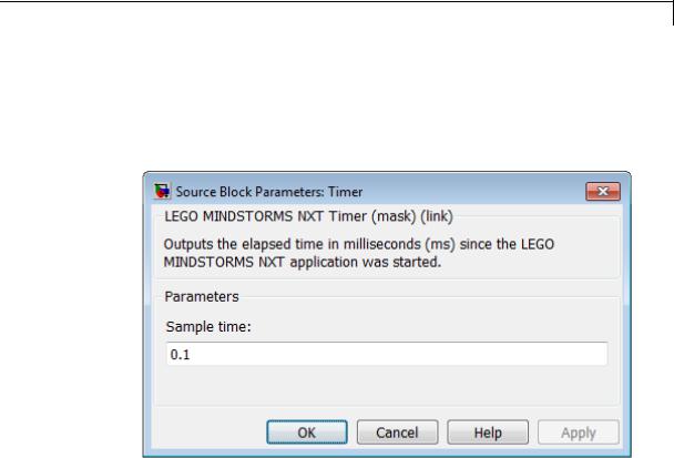
LEGO MINDSTORMS NXT Timer
2Connect the Timer block to the LCD block, as shown.
3Prepare and run the model on the NXT brick.
4Observe the elapsed time, in milliseconds, on the LCD display.
Dialog
Box
Sample time
Specify how often the block reads timer values.
Smaller values require the processor to complete the same number of instructions in less time, which can cause task overruns.
See Also LEGO MINDSTORMS NXT Battery | LEGO MINDSTORMS NXT Button | LEGO MINDSTORMS NXT LCD | LEGO MINDSTORMS NXT Speaker | LEGO MINDSTORMS NXT Timer | “Install Support for LEGO MINDSTORMS NXT Hardware” | “Detect and Fix Task Overruns on NXT Brick” |
2-2169

LEGO MINDSTORMS NXT Timer
External • http://mindstorms.lego.com
Web Sites
2-2170
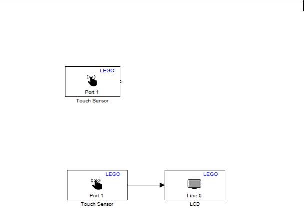
LEGO MINDSTORMS NXT Touch Sensor
Purpose |
Output state of touch sensor |
Library |
Target for Use with LEGO MINDSTORMS NXT Hardware |
Description
This block outputs the state of the LEGO MINDSTORMS 9843 Touch Sensor: 1 while pressed, and 0 while released.
If you simulate your model without running it on the target hardware, this block outputs zeroes. See “Block Produces Zeros in Simulation”.
Use the Touch Sensor
1Open the legonxtlib block library and copy the blocks shown to a new model.
2Connect the Touch block to the LCD block, as shown.
3Connect the touch sensor to Port 1 on the NXT brick.
4Prepare and run the model on the NXT brick.
5Observe the state of the touch sensor on the LCD display while you press and release the touch sensor.
2-2171

LEGO MINDSTORMS NXT Touch Sensor
Dialog
Box
See Also
External
Web Sites
NXT brick input port
Select the NXT sensor port to which the sensor is connected. Avoid assigning multiple devices to the same port. The options are 1, 2, 3, or 4.
Sample time
Specify how often the block reads sensor values.
Smaller values require the processor to complete the same number of instructions in less time, which can cause task overruns.
“Install Support for LEGO MINDSTORMS NXT Hardware” | “Detect and Fix Task Overruns on NXT Brick” |
• http://mindstorms.lego.com
2-2172
LEGO MINDSTORMS NXT Ultrasonic Sensor
Purpose |
Measure distance from object in centimeters |
Library |
Target for Use with LEGO MINDSTORMS NXT Hardware |
Description
Measure the distance between the LEGO MINDSTORMS 9846 Ultrasonic Sensor and the nearest object in front of the sensor.
The sensor can detect objects from approximately 5 to 255 centimeters away. When the nearest object is beyond the maximum range of the Ultrasonic Sensor, the sensor outputs the maximum value, 255.
The measured distances are approximate. For greater precision, calibrate the sensor output values against physical measurements.
The distance from which the sensor first detects an approaching object depends on:
•The ultrasonic reflectance of the object, which is a function of the object’s size and composition. The sensor detects large hard objects from a greater distance than small soft ones. For example, the sensor might detect a pane of glass at 255 cm and a hand puppet at 150 cm.
•The angle of incidence of the object relative to the sensor. The sensor detects objects directly in front of it at greater distances than objects off to the sides.
If you simulate your model without running it on the target hardware, this block outputs zeroes. See “Block Produces Zeros in Simulation”.
Use the Ultrasonic Sensor
With the following blocks, the output from ultrasonic sensor drives the motor forward. As the ultrasonic sensor approaches an obstacle, the output values decrease, slowing the motor.
2-2173
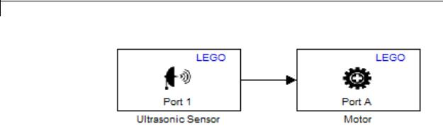
LEGO MINDSTORMS NXT Ultrasonic Sensor
1Open the legonxtlib block library and copy the blocks shown to a new model.
2Connect the Ultrasonic Sensor block to the Motor block, as shown.
3Connect the ultrasonic sensor to Port 1 on the NXT brick, and connect the servo motor to Port A on the NXT brick.
4Prepare and run the model on the NXT brick.
5Observe the speed of the motor decrease as you hold the ultrasonic sensor closer to an object.
2-2174
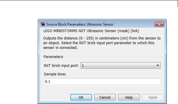
LEGO MINDSTORMS NXT Ultrasonic Sensor
Dialog
Box
NXT brick input port
Select the NXT sensor port to which the sensor is connected. Avoid assigning multiple devices to the same port. The options are 1, 2, 3, or 4.
Sample time
|
Specify how often the block reads sensor values. This value |
|
defaults to 0.1. Shorter sample times, such as 0.01, may produce |
|
unreliable measurements. |
|
Smaller values require the processor to complete the same number |
|
of instructions in less time, which can cause task overruns. |
See Also |
“Install Support for LEGO MINDSTORMS NXT Hardware” | “Detect |
|
and Fix Task Overruns on NXT Brick” | |
2-2175

LEGO MINDSTORMS NXT Ultrasonic Sensor
External • http://mindstorms.lego.com
Web Sites
2-2176