

- •Block Reference
- •Commonly Used
- •Continuous
- •Discontinuities
- •Discrete
- •Logic and Bit Operations
- •Lookup Tables
- •Math Operations
- •Model Verification
- •Model-Wide Utilities
- •Ports & Subsystems
- •Signal Attributes
- •Signal Routing
- •Sinks
- •Sources
- •User-Defined Functions
- •Additional Math & Discrete
- •Additional Discrete
- •Additional Math: Increment — Decrement
- •Run on Target Hardware
- •Target for Use with Arduino Hardware
- •Target for Use with BeagleBoard Hardware
- •Target for Use with LEGO MINDSTORMS NXT Hardware
- •Blocks — Alphabetical List
- •Command-Line Information
- •Command-Line Information
- •Command-Line Information
- •Command-Line Information
- •Command-Line Information
- •Command-Line Information
- •Command-Line Information
- •Command-Line Information
- •Command-Line Information
- •Command-Line Information
- •Command-Line Information
- •Command-Line Information
- •Command-Line Information
- •Command-Line Information
- •Command-Line Information
- •Command-Line Information
- •Settings Pane
- •Measurements Pane
- •Signal Statistics Measurements
- •Settings Pane
- •Transitions Pane
- •Overshoots/Undershoots
- •Cycles
- •Settings Pane
- •Peaks Pane
- •Command-Line Information
- •Command-Line Information
- •Command-Line Information
- •Command-Line Information
- •Command-Line Information
- •Command-Line Information
- •Command-Line Information
- •Command-Line Information
- •Command-Line Information
- •Function Reference
- •Model Construction
- •Simulation
- •Linearization and Trimming
- •Data Type
- •Examples
- •Main Toolbar
- •Command-Line Alternative
- •Command-Line Alternative
- •Command-Line Alternative
- •Command-Line Alternative
- •Command-Line Alternative
- •Command-Line Alternative
- •Mask Icon Drawing Commands
- •Simulink Classes
- •Model Parameters
- •About Model Parameters
- •Examples of Setting Model Parameters
- •Common Block Parameters
- •About Common Block Parameters
- •Examples of Setting Block Parameters
- •Block-Specific Parameters
- •Mask Parameters
- •About Mask Parameters
- •Notes on Mask Parameter Storage
- •Simulink Identifier
- •Simulink Identifier
- •Model Advisor Checks
- •Simulink Checks
- •Simulink Check Overview
- •See Also
- •Identify unconnected lines, input ports, and output ports
- •Description
- •Results and Recommended Actions
- •Capabilities and Limitations
- •Tips
- •See Also
- •Check root model Inport block specifications
- •Description
- •Results and Recommended Actions
- •See Also
- •Check optimization settings
- •Description
- •Results and Recommended Actions
- •Tips
- •See Also
- •Description
- •Results and Recommended Actions
- •See Also
- •Check for implicit signal resolution
- •Description
- •Results and Recommended Actions
- •See Also
- •Check for optimal bus virtuality
- •Description
- •Results and Recommended Actions
- •Capabilities and Limitations
- •See Also
- •Description
- •Results and Recommended Actions
- •Capabilities and Limitations
- •See Also
- •Identify disabled library links
- •Description
- •Results and Recommended Actions
- •Capabilities and Limitations
- •Tips
- •See Also
- •Identify parameterized library links
- •Description
- •Results and Recommended Actions
- •Capabilities and Limitations
- •Tips
- •See Also
- •Identify unresolved library links
- •Description
- •Results and Recommended Actions
- •Capabilities and Limitations
- •See Also
- •Results and Recommended Actions
- •Capabilities and Limitations
- •See Also
- •Results and Recommended Actions
- •Capabilities and Limitations
- •See Also
- •Check usage of function-call connections
- •Description
- •Results and Recommended Actions
- •See Also
- •Check signal logging save format
- •Description
- •Results and Recommended Actions
- •See Also
- •Description
- •Results and Recommended Actions
- •See Also
- •Description
- •Results and Recommended Actions
- •Tips
- •See Also
- •Check data store block sample times for modeling errors
- •Description
- •Results and Recommended Actions
- •See Also
- •Check for potential ordering issues involving data store access
- •Description
- •Results and Recommended Actions
- •Tips
- •See Also
- •Check for partial structure parameter usage with bus signals
- •Description
- •Results and Recommended Actions
- •Tips
- •See Also
- •Check for calls to slDataTypeAndScale
- •Description
- •Results and Recommended Actions
- •Tips
- •See Also
- •Check for proper bus usage
- •Description
- •Results and Recommended Actions
- •Action Results
- •Tips
- •See Also
- •Description
- •Results and Recommended Actions
- •See Also
- •Description
- •Results and Recommended Actions
- •See Also
- •Check for proper Merge block usage
- •Description
- •Input Parameters
- •Results and Recommended Actions
- •See Also
- •Description
- •Results and Recommended Actions
- •Action Results
- •See Also
- •Check for non-continuous signals driving derivative ports
- •Description
- •Results and Recommended Actions
- •See Also
- •Runtime diagnostics for S-functions
- •Description
- •Results and Recommended Actions
- •See Also
- •Check file for foreign characters
- •Description
- •Results and Recommended Actions
- •Tips
- •See Also
- •Check model for known block upgrade issues
- •Description
- •Results and Recommended Actions
- •Action Results
- •See Also
- •Description
- •Results and Recommended Actions
- •Action Results
- •See Also
- •Check that the model is saved in SLX format
- •Description
- •Results and Recommended Actions
- •Tips
- •See Also
- •Check Model History properties
- •Description
- •Results and Recommended Actions
- •See Also
- •Analyze model hierarchy for upgrade issues
- •Description
- •Results and Recommended Actions
- •Tips
- •See Also
- •Description
- •Results and Recommended Actions
- •See Also
- •Simulink Performance Advisor Checks
- •Simulink Performance Advisor Check Overview
- •See Also
- •Baseline
- •See Also
- •Check Preupdate Items
- •See Also
- •Checks that need Update Diagram
- •See Also
- •Checks that require simulation to run
- •See Also
- •Check Accelerator Settings
- •See Also
- •Create Baseline
- •See Also
- •Identify resource intensive diagnostic settings
- •See Also
- •Check optimization settings
- •See Also
- •Identify inefficient lookup table blocks
- •See Also
- •Identify Interpreted MATLAB Function blocks
- •See Also
- •Check MATLAB Function block debug settings
- •See Also
- •Check Stateflow block debug settings
- •See Also
- •Identify simulation target settings
- •See Also
- •Check model reference rebuild setting
- •See Also
- •Check Model Reference parallel build
- •See Also
- •Check solver type selection
- •See Also
- •Select normal or accelerator simulation mode
- •See Also
- •Simulink Limits
- •Maximum Size Limits of Simulink Models
- •Index
- •Filter Structures and Filter Coefficients
- •Valid Initial States
- •Number of Delay Elements (Filter States)
- •Frame-Based Processing
- •Sample-Based Processing
- •Valid Initial States
- •Frame-Based Processing
- •Sample-Based Processing
- •Model Parameters in Alphabetical Order
- •Common Block Parameters
- •Continuous Library Block Parameters
- •Discontinuities Library Block Parameters
- •Discrete Library Block Parameters
- •Logic and Bit Operations Library Block Parameters
- •Lookup Tables Block Parameters
- •Math Operations Library Block Parameters
- •Model Verification Library Block Parameters
- •Model-Wide Utilities Library Block Parameters
- •Ports & Subsystems Library Block Parameters
- •Signal Attributes Library Block Parameters
- •Signal Routing Library Block Parameters
- •Sinks Library Block Parameters
- •Sources Library Block Parameters
- •User-Defined Functions Library Block Parameters
- •Additional Discrete Block Library Parameters
- •Additional Math: Increment - Decrement Block Parameters
- •Mask Parameters

Enable
States when enabling
At the instant when an enabled system is being disabled, specify what happens to the states of blocks in the enabled system.
Settings
Default: held
held
Holds the states at their previous values.
reset
Resets the states to their initial conditions (zero if not defined).
Command-Line Information
Parameter: StatesWhenEnabling
Type: string
Value: 'held' | 'reset'
Default: 'held'
2-567

Enable
Propagate sizes of variable-size signals
Specify when to propagate a variable-size signal.
Settings
Default: Only when enabling
Only when enabling
Propagates variable-size signals only when reenabling the system containing the Enable Port block. When you select this option, sample time must be periodic.
During execution
Propagates variable-size signals at each time step.
Command-Line Information
Parameter: PropagateVarSize
Type: string
Value: 'Only when enabling' | 'During execution' Default: 'Only when enabling'
2-568

Enable
Show output port
Select this check box to output the enabling signal.
Settings
Default: On
 On
On
Shows the Enable block output port and outputs the enabling signal. Selecting this option allows the system to process the enabling signal.
 Off
Off
Removes the output port from the Enable block.
Command-Line Information
Parameter: ShowOutputPort
Type: string
Value: 'on' | 'off'
Default: 'on'
2-569

Enable
Enable zero-crossing detection
Select this check box to enable zero-crossing detection.
Settings
Default: On
 On
On
Detect zero crossings.
 Off
Off
Do not detect zero crossings.
Command-Line Information
Parameter: ZeroCross
Type: string
Value: 'on' | 'off'
Default: 'on'
2-570

Enable
Port dimensions
Specify the dimensions of the input signal to the block.
Settings
Default: 1
Valid values are:
n |
Vector signal of width n accepted |
[m n] |
Matrix signal having m rows and n columns accepted |
|
|
Command-Line Information
See “Block-Specific Parameters” on page 8-109 for the command-line information.
2-571

Enable
Sample time
Specify the time interval between samples.
Settings
Default: -1
See “Specify Sample Time” in the online documentation for more information.
Command-Line Information
See “Block-Specific Parameters” on page 8-109 for the command-line information.
2-572
Enable
Minimum
Specify the minimum value that the block should output.
Settings
Default: [] (unspecified)
This number must be a finite real double scalar value.
Note If you specify a bus object as the data type for this block, do not set the minimum value for bus data on the block. Simulink ignores this setting. Instead, set the minimum values for bus elements of the bus object specified as the data type. For information on the Minimum property of a bus element, see Simulink.BusElement.
Simulink software uses this value to perform:
•Simulation range checking (see “Signal Ranges”)
•Automatic scaling of fixed-point data types
Command-Line Information
See “Block-Specific Parameters” on page 8-109 for the command-line information.
2-573

Enable
Maximum
Specify the maximum value that the block should output.
Settings
Default: [] (unspecified)
This number must be a finite real double scalar value.
Note If you specify a bus object as the data type for this block, do not set the maximum value for bus data on the block. Simulink ignores this setting. Instead, set the maximum values for bus elements of the bus object specified as the data type. For information on the Maximum property of a bus element, see Simulink.BusElement.
Simulink software uses this value to perform:
•Simulation range checking (see “Signal Ranges”)
•Automatic scaling of fixed-point data types
Command-Line Information
See “Block-Specific Parameters” on page 8-109 for the command-line information.
2-574

Enable
Data type
Specify the output data type of the external input.
Settings
Default: double
double
Data type is double.
single
Data type is single.
int8
Data type is int8.
uint8
Data type is uint8.
int16
Data type is int16.
uint16
Data type is uint16.
int32
Data type is int32.
uint32
Data type is uint32.
boolean
Data type is boolean.
fixdt(1,16,0)
Data type is fixed point fixdt(1,16,0).
fixdt(1,16,2^0,0)
Data type is fixed point fixdt(1,16,2^0,0).
<data type expression>
The name of a data type object, for example
Simulink.NumericType
2-575

Enable
Do not specify a bus object as the expression.
Command-Line Information
See “Block-Specific Parameters” on page 8-109 for the command-line information.
2-576

Enable
Show data type assistant
Display the Data Type Assistant.
Settings
The Data Type Assistant helps you set the Output data type parameter.
For more information, see “Specify Block Output Data Types”.
Command-Line Information
See “Block-Specific Parameters” on page 8-109 for the command-line information.
2-577

Enable
Mode
Select the category of data to specify.
Settings
Default: double
Built in
Built-in data types. Selecting Built in enables a second menu/text box to the right. Select one of the following choices:
•double (default)
•single
•int8
•uint8
•int16
•uint16
•int32
•uint32
•boolean
Fixed point
Fixed-point data types.
Expression
Expressions that evaluate to data types. Selecting Expression enables a second menu/text box to the right, where you can enter the expression.
Do not specify a bus object as the expression.
Dependency
Clicking the Show data type assistant button enables this parameter.
2-578

Enable
Command-Line Information
See “Block-Specific Parameters” on page 8-109 for the command-line information.
See Also
See “Specify Data Types Using Data Type Assistant”.
2-579

Enable
Interpolate data
Cause the block to interpolate or extrapolate output at time steps for which no corresponding workspace data exists when loading data from the workspace.
Settings
Default: On
 On
On
Cause the block to interpolate or extrapolate output at time steps for which no corresponding workspace data exists when loading data from the workspace.
 Off
Off
Do not cause the block to interpolate or extrapolate output at time steps for which no corresponding workspace data exists when loading data from the workspace.
Command-Line Information
See “Block-Specific Parameters” on page 8-109 for the command-line information.
Characteristics |
Sample Time |
Determined by the signal at the enable |
|
|
port |
|
Dimensionalized |
Yes |
|
Virtual |
Yes, if not connected directly to an |
|
|
Outport block |
|
|
For more information, see |
|
|
“Virtual Blocks” in the Simulink |
|
|
documentation. |
|
Zero-Crossing Detection |
Yes, if enabled |
|
|
|
2-580

Enabled and Triggered Subsystem
Purpose |
Represent subsystem whose execution is enabled and triggered by |
|
external input |
Library |
Ports & Subsystems |
Description |
|
This block is a Subsystem block that is preconfigured to serve as the starting point for creating an enabled and triggered subsystem. For more information, see “Triggered and Enabled Subsystems” in the online Simulink help.
2-581

Enabled Subsystem
Purpose |
Represent subsystem whose execution is enabled by external input |
Library |
Ports & Subsystems |
Description |
This block is a Subsystem block that is preconfigured to serve as the |
|
starting point for creating an enabled subsystem. For more information, |
|
see “Enabled Subsystems” in the “Creating a Model” chapter of the |
|
Simulink documentation. |
2-582
Enumerated Constant
Purpose |
Generate enumerated constant value |
Library Sources
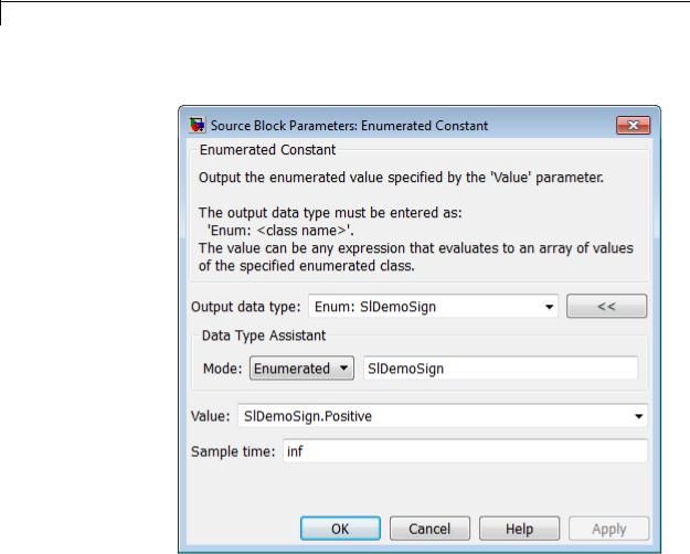
Description The Enumerated Constant block outputs a scalar, array, or matrix of enumerated values. You can also use the Constant block to output enumerated values, but it provides block parameters that do not apply to enumerated types, such as Output minimum and Output maximum. When you need a block that outputs only constant enumerated values, preferably use Enumerated Constant rather than Constant. For more information, see “About Simulink Enumerations”.
Data Type
Support
The Enumerated Constant block supports only enumerated data types. Use the Constant block to output constant data of other types. For more information, see “Data Types Supported by Simulink”.
2-583
Enumerated Constant
Parameters The Enumerated Constant block dialog box initially appears as follows:
and Dialog Box
Output data type
The Output data type field specifies the enumerated type from which you want the block to output one or more values. The initial value, Enum: SlDemoSign, is a dummy enumerated type that prevents a newly cloned block from causing an error. To specify the desired enumerated type, select it from the pulldown or enter Enum: ClassName in the Output data type field, where ClassName is the name of the MATLAB class that defines the type.
2-584

Enumerated Constant
Command-Line Information
See “Block-Specific Parameters” on page 8-109 for the command-line information.
Value
The Value field specifies the value(s) that the block outputs. The output of the block has the same dimensions and elements as the Value parameter. The initial value, SlDemoSign.Positive, is a dummy enumerated value that prevents a newly cloned block from causing
an error.
To specify the desired enumerated value(s), select from the pulldown or enter any MATLAB expression that evaluates to the desired result, including an expression that uses tunable parameters. All values specified must be of the type indicated by the Output data type. To specify an array that includes every value in the enumerated type, use the enumeration function.
Command-Line Information
See “Block-Specific Parameters” on page 8-109 for the command-line information.
Sample time
Specify the interval between times that the Constant block output can change during simulation (for example, due to tuning the Constant value parameter).
Settings
Default: inf
This setting indicates that the block output can never change. This setting speeds simulation and generated code by avoiding the need to recompute the block output. See “Specify Sample Time” for more information.
Command-Line Information
See “Block-Specific Parameters” on page 8-109 for the command-line information.
2-585

Enumerated Constant
Characteristics |
Direct Feedthrough |
N/A |
|
Sample Time |
Specified in the Sample time parameter |
|
Scalar Expansion |
No |
|
Dimensionalized |
Yes |
|
Multidimensionalized |
Yes |
|
Zero-Crossing Detection |
No |
|
|
|
2-586

Environment Controller
Purpose
Library
Description
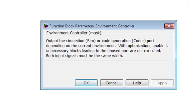
Create branches of block diagram that apply only to simulation or only to code generation
Signal Routing
This block outputs the signal at its Sim port only if the model that contains it is being simulated. It outputs the signal at its Coder port only if code is being generated from the model. This option enables you to create branches of a block diagram that apply only to simulation or code generation. The table below describes various scenarios where either the Sim or Coder port applies.
|
Scenario |
Output |
|
|
Normal mode simulation |
Sim |
|
|
Accelerator mode simulation |
Sim |
|
|
Rapid Accelerator mode |
Coder |
|
|
simulation |
|
|
|
Simulation of a referenced model |
Sim |
|
|
(Normal or Accelerator modes) |
|
|
|
Simulation of a referenced model |
Coder |
|
|
(Processor-in-the-loop (PIL) |
(uses the same code generated for |
|
|
mode) |
a referenced model) |
|
|
External mode simulation |
Coder |
|
|
Standard code generation |
Coder |
|
|
Code generation of a referenced |
Coder |
|
|
model |
|
|
2-587

Environment Controller
Data Type
Support
Simulink Coder software does not generate code for blocks connected to the Sim port if these conditions hold:
•You select the Inline parameters check box on the Optimization > Signals and Parameters pane of the Configuration Parameters dialog box.
•The blocks connected to the Sim port do not have external signals.
•The Sim port input path does not contain a MATLAB S-function or an Interpreted MATLAB Function block.
If you enable block reduction optimization, Simulink eliminates blocks in the branch connected to the Coder port when compiling the model for simulation. For information about block reduction, see “Block reduction” in the online Simulink documentation.
Note Simulink Coder code generation eliminates the blocks connected to the Sim branch only if the Sim branch has the same signal dimensions as the Coder branch. Regardless of whether it eliminates the Sim branch, Simulink Coder uses the sample times on the Sim branch as well as the Coder branch to determine the fundamental sample time of the generated code and might, in some cases, generate sample-time handling code that applies only to sample times specified on the Sim branch.
The Environment Controller block accepts signals of any data type that Simulink supports. The output uses the same data type as the input.
For more information, see “Data Types Supported by Simulink” in the Simulink documentation.
2-588
Environment Controller
Parameters and Dialog Box
Characteristics |
Multidimensionalized |
Yes |
2-589

Extract Bits
Purpose |
Output selection of contiguous bits from input signal |
Library |
Logic and Bit Operations |
Description |
|
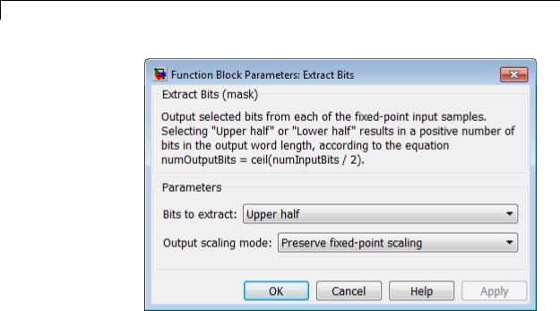
The Extract Bits block allows you to output a contiguous selection of bits from the stored integer value of the input signal. Use the Bits to extract parameter to define the method for selecting the output bits.
•Select Upper half to output the half of the input bits that contain the most significant bit. If there is an odd number of bits in the input signal, the number of output bits is given by the equation
number of output bits = ceil(number of input bits/2)
•Select Lower half to output the half of the input bits that contain the least significant bit. If there is an odd number of bits in the input signal, the number of output bits is given by the equation
number of output bits = ceil(number of input bits/2)
• Select Range starting with most significant bit to output a certain number of the most significant bits of the input signal.
Specify the number of most significant bits to output in the Number of bits parameter.
•Select Range ending with least significant bit to output a certain number of the least significant bits of the input signal. Specify the number of least significant bits to output in the Number of bits parameter.
2-590

Extract Bits
Data Type
Support
•Select Range of bits to indicate a series of contiguous bits of the input to output in the Bit indices parameter. You indicate the range in [start end] format, and the indices of the input bits are labeled contiguously starting at 0 for the least significant bit.
The Extract Bits block accepts inputs of any numeric data type that Simulink supports, including fixed-point data types. Floating-point inputs are passed through the block unchanged. Boolean inputs are treated as uint8 signals.
Note Performing bit operations on a signed integer is difficult. You can avoid difficulty by converting the data type of your input signals to unsigned integer types.
For more information, see “Data Types Supported by Simulink” in the Simulink documentation.
2-591
Extract Bits
Parameters and Dialog Box
Bits to extract
Select the method for extracting bits from the input signal.
Number of bits
(Not shown on dialog above.) Select the number of bits to output from the input signal. Signed integer data types can have no less then two bits in them. Unsigned data integer types can be as short as a single bit.
This parameter is only visible if you select Range starting
with most significant bit or Range ending with least significant bit for the Bits to extract parameter.
Bit indices
(Not shown on dialog above.) Specify a contiguous range of bits of the input signal to output. Specify the range in [start end] format. The indices are assigned to the input bits starting with 0 at the least significant bit.
2-592
Extract Bits
This parameter is only visible if you select Range of bits for the Bits to extract parameter.
Output scaling mode
|
Select the scaling mode to use on the output bits selection: |
|
|
• When you select Preserve fixed-point scaling, the fixed-point |
|
|
scaling of the input is used to determine the output scaling during |
|
|
the data type conversion. |
|
|
• When you select Treat bit field as an integer, the fixed-point |
|
|
scaling of the input is ignored, and only the stored integer is used to |
|
|
compute the output data type. |
|
Example |
Consider an input signal that is represented in binary by 110111001: |
|
|
• If you select Upper half for the Bits to extract parameter, the |
|
|
output is 11011 in binary. |
|
|
• If you select Lower half for the Bits to extract parameter, the |
|
|
output is 11001 in binary. |
|
|
• If you select Range starting with most significant bit for the |
|
|
Bits to extract parameter, and specify 3 for the Number of bits |
|
|
parameter, the output is 110 in binary. |
|
|
• If you select Range ending with least significant bit for the |
|
|
Bits to extract parameter, and specify 8 for the Number of bits |
|
|
parameter, the output is 10111001 in binary. |
|
|
• If you select Range of bits for the Bits to extract parameter, and |
|
|
specify [4 7] for the Bit indices parameter, the output is 1011 in |
|
|
binary. |
|
Characteristics |
|
|
Direct Feedthrough |
Yes |
|
|
Sample Time |
Inherited |
|
Scalar Expansion |
N/A |
|
|
|
2-593

Extract Bits
States |
None |
Dimensionalized |
Inherited |
Multidimensionalized |
Yes |
Zero Crossing |
No |
|
|
2-594

Fcn
Purpose
Library
Description
Apply specified expression to input
User-Defined Functions
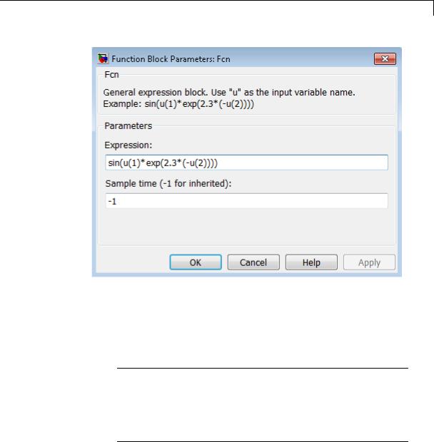
The Fcn block applies the specified mathematical expression to its input. The expression can include one or more of these components:
•u — The input to the block. If u is a vector, u(i) represents the ith element of the vector; u(1) or u alone represents the first element.
•Numeric constants
•Arithmetic operators (+ - * / ^)
• Relational operators (== != > < >= <=) — The expression returns 1 if the relation is true; otherwise, it returns 0.
•Logical operators (&& || !) — The expression returns 1 if the relation is true; otherwise, it returns 0.
•Parentheses
•Mathematical functions — abs, acos, asin, atan, atan2, ceil, cos, cosh, exp, fabs, floor, hypot, ln, log, log10, pow, power, rem, sgn, sin, sinh, sqrt, tan, and tanh.
Note The Fcn block does not support round and fix. Use the Rounding Function block to apply these rounding modes.
•Workspace variables — Variable names that are not recognized in the preceding list of items are passed to MATLAB for evaluation. Matrix or vector elements must be specifically referenced (e.g., A(1,1) instead of A for the first element in the matrix).
2-595

Fcn
Data Type
Support
The Fcn block observes the following rules of operator precedence:
1 ( )
2^
3+ - (unary)
4!
5* /
6+ -
7> < <= >=
8== !=
9&&
10||
The expression differs from a MATLAB expression in that the expression cannot perform matrix computations. Also, this block does not support the colon operator (:).
Block input can be a scalar or vector. The output is always a scalar. For vector output, consider using the Math Function block. If a block input is a vector and the function operates on input elements individually (for example, the sin function), the block operates on only the first vector element.
The Fcn block accepts and outputs signals of type single or double.
For more information, see “Data Types Supported by Simulink” in the Simulink documentation.
2-596
Fcn
Parameters and Dialog Box
Expression
Specify the mathematical expression to apply to the input. Expression components are listed above. The expression must be mathematically well-formed (uses matched parentheses, proper number of function arguments, and so on).
Note You cannot tune this expression during simulation in Normal or Accelerator mode (see “How Acceleration Modes Work”), or in generated code.
The Fcn block does not support custom storage classes. See “Custom Storage Classes” in the Embedded Coder documentation.
2-597

Fcn
Sample time (-1 for inherited)
Specify the time interval between samples. To inherit the sample time, set this parameter to -1. See “Specify Sample Time” in the online documentation for more information.
Examples The following example models show how to use the Fcn block:
•sldemo_absbrake
•sldemo_enginewc (Throttle & Manifold/Throttle subsystem)
Characteristics |
Direct Feedthrough |
Yes |
|
Sample Time |
Inherited from the driving block |
|
Scalar Expansion |
No |
|
Dimensionalized |
No |
|
Multidimensionalized |
No |
|
Zero-Crossing Detection |
No |
|
|
|
2-598

Find
Purpose |
Find nonzero elements in array |
Library |
Math Operations |
Description |
The Find block locates all nonzero elements of the input signal |
|
and returns the linear indices of those elements. If the input is a |
|
multidimensional signal, the Find block can also return the subscripts |
|
of the nonzero input elements. In both cases, you can show an output |
|
port with the nonzero input values. |
Data Type
Support
The Find block accepts and outputs real values of any numeric data type that Simulink supports.
For more information, see “Data Types Supported by Simulink” in the Simulink documentation.
2-599
Find
Parameters The Main pane of the Find block dialog box appears as follows:
and Dialog Box
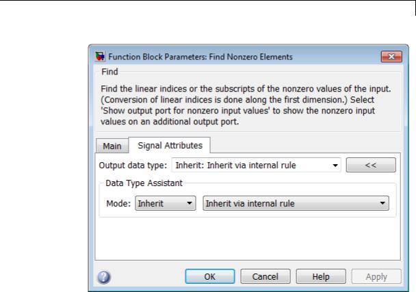
The Signal Attributes pane of the Find block dialog appears as follows:
2-600
Find
•“Index output format” on page 2-604
•“Number of input dimensions” on page 2-605
•“Index mode” on page 2-606
•“Show output port for nonzero input values” on page 2-607
•“Sample time (-1 for inherited)” on page 2-608
•“Output data type” on page 2-609
•“Mode” on page 2-611
•“Data type override” on page 2-1892
•“Signedness” on page 2-614
2-601

Find
•“Word length” on page 2-615
•“Scaling” on page 2-616
2-602
Find
2-603

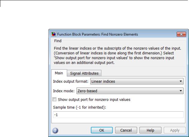
Find
Index output format
Select the output format for the indices of the nonzero input values.
Settings
Default: Linear indices
Linear indices
Provides the element indices of any dimension signal in a vector form. For one dimension (vector) signals, indices correspond to the position of nonzero values within the vector. For signals with more than one dimension, the conversion of subscripts to indices is along the first dimension. You do not need to know the signal dimension of the input signal.
Subscripts
Provides the element indices of a two-dimension or larger signal in a subscript form. Because the block shows an output port for each dimension, this option requires you to know the number of dimensions for the input signal.
Dependencies
Selecting Subscripts from the Index output format list enables the
Number of input dimensions parameter.
Command-Line Information
Parameter: IndexOutputFormat
Type: string
Value: Linear indices | Subscripts
Default: Linear indices
2-604

Find
Number of input dimensions
Specify the number of dimensions for the input signal.
Settings
Default: 1
Minimum: 1
Maximum: 32
Dependencies
Selecting Subscripts from the Index output format list enables this parameter.
Command-Line Information
Parameter: NumberOfInputDimensions
Type: int
Value: positive integer value
Default: 1
2-605

Find
Index mode
Specify the indexing mode.
Settings
Default: Zero-based
Zero-based
An index of 0 specifies the first element of the input vector. An index of 1 specifies the second element, and so on.
One-based
An index of 1specifies the first element of the input vector. An index of 2, specifies the second element , and so on.
Command-Line Information
Parameter: IndexMode
Type: string
Value: Zero-based | One-based
Default: Zero-based
2-606

Find
Show output port for nonzero input values
Show or hide the output port for nonzero input values.
Settings
Default: Off
 On
On
Display the output port for nonzero input values. The additional output port provides the values of the nonzero input elements.
 Off
Off
Hide the output port for nonzero input values.
Command-Line Information
Parameter: ShowOutputPortForNonzeroInputValues
Type: string
Value: 'on' | 'off'
Default: 'off'
2-607

Find
Sample time (-1 for inherited)
Specify the time interval between samples. To inherit the sample time, set this parameter to -1. See “Specify Sample Time” in the “How Simulink Works” chapter of the Simulink documentation.
Command-Line Information
Parameter: SampleTime
Type: string
Value: -1 (for inherited)| positive number
Default: -1
2-608

Find
Output data type
Specify the output data type.
Settings
Default: Inherit: Inherit via internal rule
Inherit: Inherit via internal rule
Output data type is defined by the target.
int8
Output data type is int8.
uint8
Output data type is uint8.
int16
Output data type is int16.
uint16
Output data type is uint16.
int32
Output data type is int32.
uint32
Output data type is unt32.
fixdt(1,16)
Output data type is fixed point, fixdt(1,16).
<data type expression>
Use a data type object, for example, Simulink.NumericType.
Click the Show data type assistant button  to display additional parameters for the Output data type parameter.
Command-Line Information
Parameter: OutDataTypeStr
Type: string
2-609

Find
Value: 'Inherit: |
Inherit via internal rule' | 'int8' |
| 'uint8' | 'int16' | 'uint16' | 'int32' | 'uint32'| |
|
'fixdt(1,16)'| '<data type expression>' |
|
Default: 'Inherit: |
Inherit via internal rule' |
See Also
“Specify Block Output Data Types”, “Specify Data Types Using Data
Type Assistant”
2-610

Find
Mode
Select the category of data to specify.
Settings
Default: Inherit
Inherit
Inheritance rules for data types. Selecting Inherit enables a second list of the possible values:
•Inherit via internal rule (Discrete-Time Integrator, Gain, Product, Sum, Switch block default)
Built in
Built-in data types. Selecting Built in enables a second list of the possible values:
•int8
•uint8
•int16
•uint16
•int32
•uint32
Fixed point
Fixed-point data types.
Expression
Expressions that evaluate to data types. Selecting Expression enables a second text box, where you can enter the expression.
Dependencies
Clicking the Show data type assistant button enables this parameter.
Selecting Fixed point from the Mode list enables the following parameters:
• Signed
2-611

Find
•Scaling
•Word length
See Also
“Specify Data Types Using Data Type Assistant”
2-612
Find
Data type override
Specify data type override mode for this signal.
Settings
Default: Inherit
Inherit
Inherits the data type override setting from its context, that is, from the block, Simulink.Signal object or Stateflow chart in Simulink that is using the signal.
Off
Ignores the data type override setting of its context and uses the fixed-point data type specified for the signal.
Tip
The ability to turn off data type override for an individual data type provides greater control over the data types in your model when you apply data type override. For example, you can use this option to ensure that data types meet the requirements of downstream blocks regardless of the data type override setting.
Dependency
This parameter appears only when the Mode is Built in or Fixed point.
2-613

Find
Signedness
Specify whether the fixed-point data is signed or unsigned.
Settings
Default: Signed
Signed
Specifies the fixed-point data as signed.
Unsigned
Specifies the fixed-point data as unsigned.
Dependency
Selecting Fixed point from the Mode list enables this parameter.
2-614

Find
Word length
Specify the bit size of the word that holds the quantized integer.
Settings
Default: 16
Minimum: 0
Maximum: 32
Large word sizes represent large values with greater precision than small word sizes.
Dependency
Selecting Fixed point from the Mode list enables this parameter.
2-615

Find
Scaling
Specify the method for scaling your fixed-point data to avoid overflow conditions and minimize quantization errors.
Settings
Default: Integer
Integer
Specifies a binary point location for fixed-point data and sets the fraction length to 0.
The Scaling list has only one item for you to select.
Dependency
Selecting Fixed point from the Mode list enables this parameter.
Characteristics |
Direct Feedthrough |
Yes |
|
Sample Time |
Specified in the Sample time |
|
|
parameter |
|
Scalar Expansion |
No |
|
Dimensionalized |
Yes |
|
Multidimensionalized |
Yes |
|
Zero-Crossing Detection |
No |
|
|
|
2-616

First-Order Hold
Purpose
Library
Description
Data Type
Support
Implement first-order sample-and-hold
Discrete
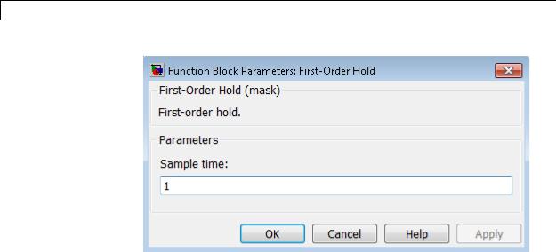
The First-Order Hold block implements a first-order sample-and-hold that operates at the specified sampling interval. This block has little value in practical applications and is included primarily for academic purposes.
This figure compares the output from a Sine Wave block and a First-Order Hold block.
The First-Order Hold block accepts and outputs signals of type double. For more information, see “Data Types Supported by Simulink” in the Simulink documentation.
2-617
First-Order Hold
Parameters and
Dialog |
Sample time |
|
||
Box |
The time interval between samples. See “Specify Sample Time” in |
|||
the online documentation for more information. |
||||
|
|
|||
Characteristics |
|
|
|
|
|
Direct Feedthrough |
No |
||
|
|
Sample Time |
Specified in the Sample time |
|
|
|
|
parameter |
|
|
|
Scalar Expansion |
No |
|
|
|
States |
1 continuous and 1 discrete per input |
|
|
|
|
element |
|
|
|
Dimensionalized |
Yes |
|
|
|
Zero Crossing |
No |
|
See Also |
|
Zero-Order Hold |
|
|
2-618

Fixed-Point State-Space
Purpose
Library
Description
Implement discrete-time state space
Additional Math & Discrete / Additional Discrete
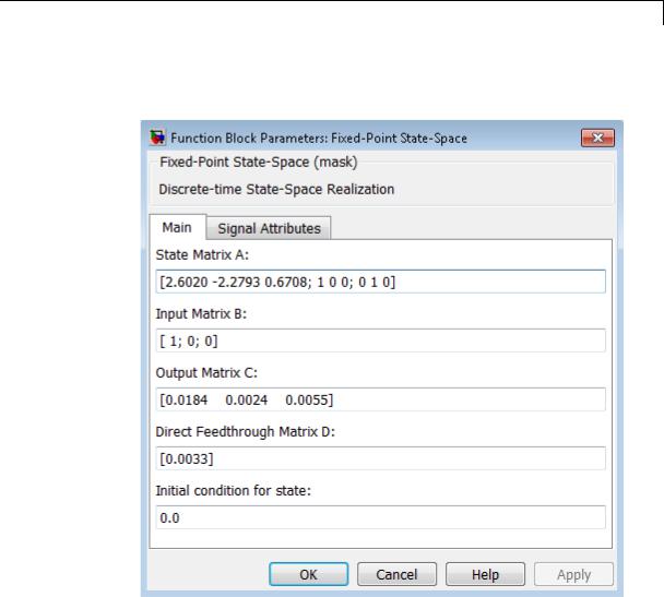
The Fixed-Point State-Space block implements the system described by
y(n) = Cx(n) + Du(n)
x(n+1) = Ax(n) + Bu(n)
where u is the input, x is the state, and y is the output. Both equations have the same data type.
The matrices A, B, C and D have the following characteristics:
•A must be an n-by-n matrix, where n is the number of states.
•B must be an n-by-m matrix, where m is the number of inputs.
•C must be an r-by-n matrix, where r is the number of outputs.
•D must be an r-by-m matrix.
In addition:
•The state x must be an n-by-1 vector.
•The input u must be an m-by-1 vector.
•The output y must be an r-by-1 vector.
2-619

Fixed-Point State-Space
Data Type
Support
The block accepts one input and generates one output. The block determines the input vector width by the number of columns in the B and D matrices. Similarly, the block determines the output vector width by the number of rows in the C and D matrices.
The Fixed-Point State-Space block accepts signals of the following data types:
•Floating point
•Built-in integer
•Fixed point
For more information, see “Data Types Supported by Simulink” in the Simulink documentation.
2-620
Fixed-Point State-Space
Parameters |
The Main pane of the Fixed-Point State-Space block dialog box appears |
and |
as follows: |
Dialog |
|
Box |
|
State Matrix A
Specify the matrix of states.
Input Matrix B
Specify the column vector of inputs.
2-621

Fixed-Point State-Space
Output Matrix C
Specify the column vector of outputs.
Direct Feedthrough Matrix D
Specify the matrix for direct feedthrough.
Initial condition for state
Specify the initial condition for the state.
The Signal Attributes pane of the Fixed-Point State-Space block dialog box appears as follows:
2-622
Fixed-Point State-Space
Data type for internal calculations
Specify the data type for internal calculations.
Scaling for State Equation AX+BU
Specify the scaling for state equations.
Scaling for Output Equation CX+DU
Specify the scaling for output equations.
2-623

Fixed-Point State-Space
Lock output data type setting against changes by the fixed-point tools
Select to lock the output data type setting of this block against changes by the Fixed-Point Tool and the Fixed-Point Advisor. For more information, see “Use Lock Output Data Type Setting”.
Integer rounding mode
Specify the rounding mode for fixed-point operations. For more information, see “Rounding”. in the Simulink Fixed Point documentation.
Saturate to max or min when overflows occur
Select to have overflows saturate to the maximum or minimum value that the data type can represent. Otherwise, overflows wrap.
When you select this check box, saturation applies to every internal operation on the block, not just the output or result. In general, the code generation process can detect when overflow is not possible. In this case, the code generator does not produce saturation code.
Characteristics
See Also
Direct Feedthrough |
Yes |
Scalar Expansion |
Yes, of initial conditions |
Multidimensionalized |
No |
Zero-Crossing Detection |
No |
|
|
Discrete State-Space
2-624
For Each
Purpose |
Enable blocks inside For Each Subsystem to process elements or |
||||||||||||
|
subarrays of input signal independently |
||||||||||||
Library |
Ports & Subsystems |
|
|
|
|
||||||||
Description |
The For Each block serves as a control block for the For Each Subsystem |
||||||||||||
|
block. Specifically, the For Each block enables the blocks inside the |
||||||||||||
|
For Each Subsystem to process elements or subarrays of the input |
||||||||||||
|
signals independently. Each block inside this subsystem that has states |
||||||||||||
|
maintains a separate set of states for each element or subarray it |
||||||||||||
|
processes. As the set of blocks in the subsystem process the elements |
||||||||||||
|
(or subarrays), the subsystem concatenates the results to form output |
||||||||||||
|
signals. |
|
|
|
|
|
|
|
|||||
|
Using the For Each block, you specify how to decompose each input |
||||||||||||
|
signal to the subsystem into elements or subarrays by setting the |
||||||||||||
|
integer values of the “Partition Dimension” on page 2-632 and the |
||||||||||||
|
“Partition Width” on page 2-633. Similarly, you define the dimension |
||||||||||||
|
along which to concatenate the results by specifying the “Concatenation |
||||||||||||
|
Dimension” on page 2-635. |
||||||||||||
|
As an illustration, consider an input signal A of the form: |
||||||||||||
|
|
|
|
|
|
|
|
|
d2 |
|
|
|
|
|
|
|
|
|
|
|
|
|
|
|
|
|
|
|
|
|
|
|
|
|
|
|
|
|
|
|
|
|
|
|
|
|
|
|
|
|
|
|
|
|
|
|
|
|
|
|
|
|
|
|
|
|
|
|
|
|
d1 |
|
|
|
|
A11 |
A12 |
A13 |
|
||||
|
|
|
|
A21 |
A22 |
A23 |
|
||||||
|
|
|
|
|
|
|
A31 |
A32 |
A33 |
|
|||
|
|
|
|
|
|
|
|
|
|
|
|
|
|
The labels d1 and d2, respectively define dimension 1 and dimension 2. If you retain the default setting of 1 for both the partition dimension and the partition width, then Simulink slices perpendicular to partition dimension d1 at a width equal to the partition width, one element.
2-625

For Each
|
|
|
|
|
|
|
|
|
|
|
|
Partition |
|
|
|
A11 |
A12 |
A13 |
|
||||
|
|
|
|
||||||||
|
|
|
A21 |
A22 |
A23 |
|
|||||
|
|
|
|
||||||||
dimension |
|
|
|
||||||||
set to 1 |
|
|
|
|
|
|
|
|
|
||
|
|
|
A31 |
A32 |
A33 |
|
|||||
|
|
|
|
|
|
|
|||||
|
|
|
|
|
|
|
|||||
|
|
|
|
|
|
|
|
|
|
|
|
Input signal A decomposes into the following three row vectors:
A11 A12 A13
A21 A22 A23
A31 A32 A33
If instead you specify d2 as the partition dimension by entering the value 2, Simulink slices perpendicular to d2 to form three column vectors:
|
|
|
|
|
|
|
|
|
|
A11 |
|
|
A12 |
|
|
A13 |
|||
A21 |
|
|
A22 |
|
|
A23 |
|||
A31 |
|
|
A32 |
|
|
A33 |
|||
|
|
|
|
|
|
|
|
|
|
In either case, the results generated by the block for each subarray stack along the concatenation dimension, d1 (y-axis). Whereas, if you specify d2 by setting the concatenation dimension to 2, the results concatenate along the d2 direction (x-axis). Thus if the process generates row vectors, then the concatenated result is a row vector.
2-626
For Each
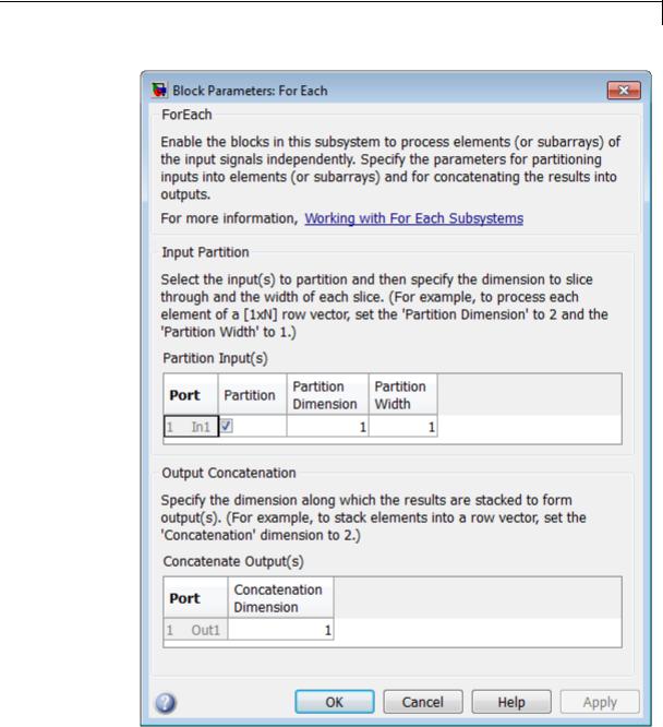
Parameters and
Dialog |
• |
“Partition Input(s)” on page 2-629 |
Box |
• |
“Port” on page 2-630 |
2-627

For Each
•“Partition” on page 2-631
•“Partition Dimension” on page 2-632
•“Partition Width” on page 2-633
•“Concatenate Output(s)” on page 2-634
•“Port” on page 2-634
•“Concatenation Dimension” on page 2-635
2-628

For Each
Partition Input(s)
Use this table to select each input signal that you need to partition and to specify the corresponding Partition Dimension and Partition Width parameters.
2-629

For Each
Port
The Port column displays the input index and the name of the input port connected to the For Each Subsystem block.
Tip
You can have any number of ports.
Command-Line Information
See “Block-Specific Parameters” on page 8-109 for the command-line information.
2-630

For Each
Partition
Select the check box beside each input signal that you want to partition into subarrays or elements.
Settings
Default: Off
 On
On
Enables the partitioning of the input signal.
 Off
Off
Disables the partitioning of the input signal.
Dependencies
Selecting this check box enables the Partition Dimension and
Partition Width parameters.
Command-Line Information
See “Block-Specific Parameters” on page 8-109 for the command-line information.
2-631

For Each
Partition Dimension
Specify the dimension through which to slice the input signal array. The resulting slices are perpendicular to the dimension that you specify. The slices also partition the array into subarrays or elements, as appropriate.
Settings
Default: 1
Minimum: 1
Tip
Specify the corresponding width of each slice by setting the Partition Width parameter for a given input port.
Command-Line Information
See “Block-Specific Parameters” on page 8-109 for the command-line information.
2-632
For Each
Partition Width
Specify the width of each partition slice of the input signal.
Settings
Default: 1
Minimum: 1
Tips
•The default width of 1 represents a width of one element.
•Specify this parameter with the Partition Dimension parameter to define fully how to create the partitioned signal.
Command-Line Information
See “Block-Specific Parameters” on page 8-109 for the command-line information.
2-633

For Each
Concatenate Output(s)
For each output port, specify the dimension along which to stack (concatenate) the For Each Subsystem results.
Port
The Port column displays the output index and the name of the output port connected to the For Each Subsystem block.
Tip
You can have any number of ports.
Command-Line Information
See “Block-Specific Parameters” on page 8-109 for the command-line information.
2-634

For Each
Concatenation Dimension
Specify the dimension along which to stack the results of the For Each Subsystem.
Settings
Default: 1
Minimum: 1
Tips
•If you specify the default, the results stack in the d1 direction. Thus if the block generates column vectors, the concatenation process results in a single column vector.
•If you specify 2, the results stack in the d2 direction. Thus if the block generates row vectors, the concatenation process results in a single row vector.
Command-Line Information
See “Block-Specific Parameters” on page 8-109 for the command-line information.
2-635
For Each
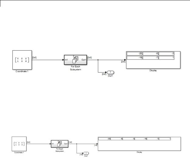
Examples
See Also
The following model demonstrates the partitioning of an input signal by a For Each block. Each row of this 2-by-3 input array contains three integers that represent the (x, y, z)-coordinates of a point. The goal is to translate each of these points based on a new origin at (–20, –10, –5) and to display the results.
By placing the process of summing an input signal and the new origin inside of a For Each Subsystem, you can operate on each set of coordinates by partitioning the input signal into two row vectors. To accomplish such partitioning, use the default settings of 1 for both the partition dimension and the partition width. If you also use the default concatenation dimension of 1, each new set of coordinates stacks in the d1 direction, making your display a 2-by-3 array.
Alternatively, if you specify a concatenation dimension of 2, then you get a single row vector because each set of results stacks in the d2 direction.
This example shows how to partition an input signal. To learn how the For Each block and subsystem handle a model with states, see the For Each Subsystem documentation.
For Each Subsystem
2-636

For Each Subsystem
Purpose |
Repeatedly perform algorithm on each element or subarray of input |
|
signal and concatenate results |
Library |
Ports & Subsystems |
Description |
|
The For Each Subsystem block is useful in modeling scenarios where you need to repeat the same algorithm for individual elements (or subarrays) of an input signal. The set of blocks within the subsystem represents the algorithm applied to a single element (or subarray) of the original signal. The For Each block inside the subsystem allows you to configure the decomposition of the subsystem inputs into elements (or subarrays), and to configure the concatenation of the individual results into output signals.
Inside this subsystem, each block that has states maintains separate sets of states for each element or subarray that it processes. Consequently, the operation of this subsystem is similar in behavior to copying the contents of the subsystem for each element in the original input signal and then processing each element using its respective copy of the subsystem.
An additional benefit of the For Each Subsystem is that, for certain models, it improves the code reuse in Simulink Coder generated code. Consider a model containing two reusable Atomic Subsystems with the same scalar algorithm applied to each element of the signal. If the input signal dimensions of these subsystems are different, Simulink Coder generated code includes two distinct functions. You can replace these two subsystems with two identical For Each Subsystems that are configured to process each element of their respective inputs using the same algorithm. For this case, Simulink Coder generated code
2-637

For Each Subsystem
consists of a single function parameterized by the number of input signal elements. This function is invoked twice — once for each unique instance of the For Each Subsystem in the model. For each of these cases, the input signal elements have different values.
Limitations
The For Each Subsystem block has these limitations, which you can work around.
|
Limitation |
Workaround |
|
|
You cannot log any signals in the |
Pull the signal outside the |
|
|
subsystem. |
subsystem using an output port |
|
|
|
for logging. |
|
|
You cannot log the states of the |
Save and restore the simulation |
|
|
blocks in the model in array |
state (SimState). |
|
|
format. Also, you cannot log |
|
|
|
the states of the blocks in the |
|
|
|
subsystem, even if you are using |
|
|
|
structure format. |
|
|
|
Reusable code is generated for |
Permute the signal dimensions to |
|
|
two For Each Subsystems with |
transform the partition dimension |
|
|
identical contents if their input |
and the concatenation dimension |
|
|
and output signals are vectors ( |
to the highest nonsingleton |
|
|
1-D or 2-D row or column vector). |
dimension for n-D signals. |
|
|
For n-D input and output signals, |
|
|
|
reusable code is generated only |
|
|
|
when the dimension along which |
|
|
|
the signal is partitioned is the |
|
|
|
highest dimension. |
|
|
The For Each Subsystem block does not support the following features:
•You cannot include the following blocks or S-functions inside a For Each Subsystem:
2-638

For Each Subsystem
-Data Store Memory, Data Store Read, or Data Store Write blocks inside the subsystem
-The From Workspace block if the input is a Structure with Time that has an empty time field.
-The To Workspace and To File data saving blocks
-Model Reference block with simulation mode set to ’Normal’
-Shadow Inports
-ERT S-functions
For a complete list of the blocks that support the For Each Subsystem, type showblockdatatypetable at the MATLAB command line.
•You cannot use the following kinds of signals:
-Test-pointed signals or signals with an external storage class inside the system
-Frame signals on subsystem input and output boundaries
-Variable-size signals
-Function-call signals crossing the boundaries of the subsystem
•Creation of a linearization point inside the subsystem
•Setting the initial state of blocks inside the model if the format of the data is in either of the following formats:
-Array
-Structure that includes data for a block inside of the For Each subsystem
•Propagating the Jacobian flag for the blocks inside the subsystem. You can check this condition in MATLAB using
J.Mi.BlockAnalyticFlags.jacobian, where J is the Jacobian object. To verify the correctness of the Jacobian of the For Each Subsystem, perform the following steps
2-639

For Each Subsystem
-Look at the tag of the For Each Subsystem Jacobian. If it is “not_supported”, then the Jacobian is incorrect.
-Move each block out of the For Each Subsystem and calculate its Jacobian. If any block is “not_supported” or has a warning tag, the For Each Subsystem Jacobian is incorrect.
•You cannot perform the following kinds of code generation:
-
-
-
-
Generation of a Simulink Coder S-function target
Simulink Coder code generation under both of the following conditions:
•A Stateflow or MATLAB Function block resides in the subsystem.
•This block tries to access global data outside the subsystem, such as Data Store Memory blocks or Simulink.Signal objects of ExportedGlobal storage class.
HDL code generation
PLC code generation
S-Function Support
The For Each Subsystem block supports both C-MEX S-functions and Level-2 MATLAB S-functions, provided that the S-function supports multiple execution instances using one of the following techniques:
•A C-MEX S-function must declare ssSupportsMultipleExecInstances(S, true) in the mdlSetWorkWidths method.
•A Level-2 MATLAB S-function must declare ’block.SupportsMultipleExecInstances = true’ in the Setup method.
If you use the above specifications:
•Do not cache run-time data, such as DWork and Block I/O, using global or persistent variables or within the userdata of the S-function.
2-640

For Each Subsystem
Data Type
Support
Examples of Working with For Each Subsystems
•Every S-function execution method from mdlStart up to mdlTerminate is called once for each element processed by the S-function, when it is in a For Each Subsystem. Consequently, you need to be careful not to free the same memory on repeated calls to mdlTerminate. For example, consider a C-MEX S-function that allocates memory for a run-time parameter within mdlSetWorkWidths. The memory only needs to be freed once in mdlTerminate. As a solution, set the pointer to be empty after the first call to mdlTerminate.
The For Each Subsystem block accepts real or complex signals of the following data types:
•Floating point
•Built-in integer
•Fixed point
•Boolean
•Enumerated
For more information, see “Data Types Supported by Simulink” in the Simulink documentation.
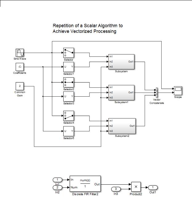
Example of Simplifying a Model
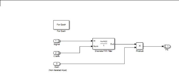
The following model uses an FIR filter to independently process each element of the input sine wave signal, in an identical manner. The model uses Selector blocks and three identical subsystems: Subsystem, Subsystem1, and Subsystem2. A Vector Concatenate block concatenates the resulting vectors. This repetitive process is graphically complex and difficult to maintain. Also, adding another element to the signal requires a significant rework of the model.
2-641
For Each Subsystem
Each subsystem contains an identical FIR filter that accepts a different set of input coefficients. For example, Subsystem2 contains the following blocks:
2-642
For Each Subsystem
You can simplify this model by replacing the repetitive operations with a single For Each Subsystem block.
This subsystem contains a For Each block and a model representing the identical algorithm of the three subsystems that it replaces. The For Each block specifies how to partition the input signal into individual elements and how to concatenate the processed signals to form output signals. Also, every block that has state maintains a separate set of states for each input element processed during a given execution step.
2-643
For Each Subsystem
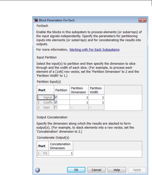
For this example, both the input signal and the input coefficients are selected for partitioning. The partition dimension and the partition width are both set to 1 for both inputs.
2-644
For Each Subsystem
2-645

For Each Subsystem
Therefore, the For Each block slices the input signals into horizontal partitions of width 1. The input signal of coefficients transforms from a single array,
|
|
|
|
|
|
|
|
|
|
|
|
|
Partition |
|
|
|
0.0284 |
0.2370 |
0.4692 |
0.2370 |
0.0284 |
|
|||
|
|
|
|
|
|
|
|
|
|
|
||
|
|
|
-0.0651 |
0.0000 |
0.8698 |
0.0000 |
-0.0651 |
|
||||
|
|
|
|
|||||||||
dimension |
|
|
|
|||||||||
set to 1 |
|
|
0.0284 |
-0.2370 |
0.4692 |
-0.2370 |
0.0284 |
|
||||
|
|
|
||||||||||
|
|
|
|
|
|
|||||||
|
|
|
|
|
|
|
|
|
|
|
|
|
into three signals,
0.0284 0.2370 0.4692 0.2370 0.0284 -0.0651 0.0000 0.8698 0.0000 -0.0651 0.0284 -0.2370 0.4692 -0.2370 0.0284
To match the output signal dimension to the input signal dimension, set the concatenation dimension equal to the partition dimension. (The output signal dimension and the input signal dimension do not have to match, but matching them makes it easier to compare the input and output.)
Example of Improved Code Reuse
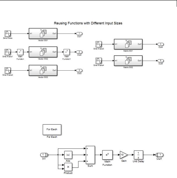
The purpose of this example is to show how code reuse can be improved when you have two or more identical For Each Subsystems. Consider the following model, rtwdemo_foreachreuse.
2-646
For Each Subsystem
The intent is for the three subsystems — Vector SS1, Vector SS2, and Vector SS3 — to apply the same processing to each scalar element of the vector signal at their respective input. Because these three subsystems perform the same processing, it is desirable for them to produce a single shared Output (and Update) function for all three subsystems in the code generated for this model. For example, the Vector SS3 subsystem contains the following blocks:
To generate a single shared function for the three subsystems, the configuration of the partitioning they perform on their input signals
2-647

For Each Subsystem
must be identical. For Vector SS1 and Vector SS3, this configuration is straightforward because you can set the partition dimension and width to 1. However, in order for Vector SS2 to also partition its input signal along dimension 1, you must insert a Math Function block to transpose the 1-by-8 row vector into an 8-by-1 column vector. You can subsequently convert the output of the subsystem back to a 1-by-8 row vector using a second Math Function block set to the transpose operator.
If you use the Build button on the Code Generation pane of the Configuration Parameters dialog to generate code, the resulting code uses a single Output function. This function is shared by all three For Each Subsystem instances.
/*
*Output and update for iterator system:
*'<Root>/Vector SS1'
*'<Root>/Vector SS2'
*'<Root>/Vector SS3'
*/
void VectorProcessing(int32_T NumIters, const real_T rtu_In1[], real_T rty_Out1[],
rtDW_VectorProcessing *localDW)
The functions has an input parameter NumIters that indicates the number of independent scalars which each For Each Subsystem is to process. This function is called three times with the parameter NumIters set to 10, 8, and 7 respectively.
The remaining two subsystems in this model show how reusable code can also be generated for matrix signals that are processed using the For Each Subsystem. Once again, a Build provides code reuse of a single function.
Characteristics |
Sample Time |
Inherited from the driving block |
|
Scalar Expansion |
No |
|
|
|
2-648

For Each Subsystem
|
|
Dimensionalized |
Yes |
|
|
Multidimensionalized |
Yes |
See Also |
|
For Each |
|
2-649
For Iterator
Purpose |
Repeatedly execute contents of subsystem at current time step until |
|
iteration variable exceeds specified iteration limit |
Library |
Ports & Subsystems |
Description |
The For Iterator block, when placed in a subsystem, repeatedly executes |
|
the contents of the subsystem at the current time step until an iteration |
|
variable exceeds a specified iteration limit. You can use this block |
|
to implement the block diagram equivalent of a for loop in the C |
|
programming language. |
|
The output of a For Iterator subsystem can not be a function-call signal. |
|
Simulink software will display an error message if the simulation is run |
|
or the diagram updated. |
|
The block’s parameter dialog allows you to specify the maximum value |
|
of the iteration variable or an external source for the maximum value |
|
and an optional external source for the next value of the iteration |
|
variable. If you do not specify an external source for the next value of |
|
the iteration variable, the next value is determined by incrementing the |
|
current value: |
|
in+1 = in +1 |
|
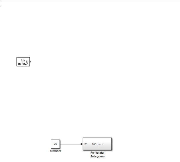
Suppose that you have the following model: |
2-650

For Iterator
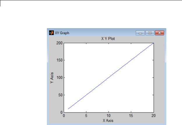
Over 20 iterations, the For Iterator block increments a value by 10 at each time step:
2-651
For Iterator
The following figure shows the result.
The For Iterator subsystem in this example is equivalent to the following C code.
sum = 0; iterations = 20; sum_increment = 10;
for (i = 0; i < iterations; i++) { sum = sum + sum_increment;
}
2-652
For Iterator
Data Type
Support
Note Placing a For Iterator block in a subsystem makes it an atomic subsystem if it is not already an atomic subsystem.
The following rules apply to the data type of the number of iterations
(N) input port:
•The input port accepts data of mixed numeric types.
•If the input port value is noninteger, it is first truncated to an integer.
•Internally, the input value is cast to an integer of the type specified for the iteration variable output port.
•If no output port is specified, the input port value is cast to type int32.
•If the input port value exceeds the maximum value of the output port’s type, it is truncated to that maximum value.
Data output for the iterator value can be selected as double, int32, int16, or int8 in the block parameters dialog box.
The following rules apply to the iteration variable input port:
•It can appear only if the iteration variable output port is enabled.
•The data type of the iteration variable input port is the same as the data type of the iteration variable output port.
For more information, see “Data Types Supported by Simulink” in the Simulink documentation.
2-653
For Iterator
Parameters
2-654

For Iterator
and Dialog Box
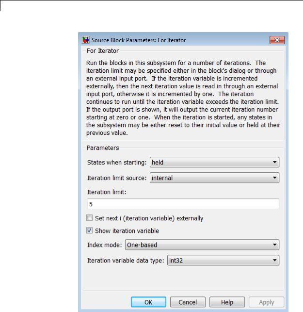
States when starting
Set this field to reset if you want the states of the For subsystem to be reinitialized before the first iteration at each time step. Otherwise, set this field to held (the default) to make sure that these subsystem states retain their values from the last iteration at the previous time step.
Iteration limit source
If you set this field to internal, the value of the Iteration limit field determines the number of iterations. If you set this field to external, the signal at the For Iterator block’s N port determines the number of iterations. The iteration limit source must reside outside the For Iterator subsystem.
Iteration limit
Set the number of iterations by specifying a number or a named constant. This field appears only if you selected internal for the Iteration limit source field. This parameter supports storage classes. You can define the named constant in the base workspace of the Model Explorer as a Simulink.Parameter object of the built-in storage class Define (custom) type. For more information, see “Apply Custom Storage Classes to Parameters” in the Embedded Coder documentation.
Set next i (iteration variable) externally
This option can be selected only if you select the Show iteration variable option. If you select this option, the For Iterator block displays an additional input for connecting an external iteration variable source. The value of the input at the current iteration is used as the value of the iteration variable at the next iteration.
Show iteration variable
If you select this check box, the For Iterator block outputs its iteration value.
Index mode
If you set this field to Zero-based, the iteration number starts at zero. If you set this field to One-based, the iteration number starts at one.
2-655

For Iterator
Iteration variable data type
Set the type for the iteration value output from the iteration number port to double, int32, int16, or int8.
Characteristics |
Direct Feedthrough |
No |
|
Sample Time |
Inherited from driving blocks |
|
Scalar Expansion |
No |
|
Dimensionalized |
No |
|
Zero Crossing |
No |
|
|
|
2-656

For Iterator Subsystem
Purpose |
Represent subsystem that executes repeatedly during simulation time |
|
step |
Library |
Ports & Subsystems |
Description |
|
The For Iterator Subsystem block is a Subsystem block that is preconfigured to serve as a starting point for creating a subsystem that executes repeatedly during a simulation time step.
For more information, see the For Iterator block in the online Simulink block reference and “Control Flow Logic” in the Simulink documentation.
When using simplified initialization mode, you cannot place any block needing elapsed time within an Iterator Subsystem. In simplified initialization mode, Iterator subsystems do not maintain elapsed time, so Simulink will report an error if any such block (such as the Discrete-Time Integrator block) is placed within the subsystem. For more information on simplified initialization modes, see “Underspecified initialization detection”.
2-657
From
Purpose |
Accept input from Goto block |
Library |
Signal Routing |
Description |
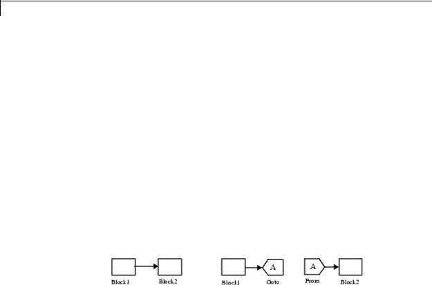
The From block accepts a signal from a corresponding Goto block, then |
|
passes it as output. The data type of the output is the same as that of |
|
the input from the Goto block. From and Goto blocks allow you to pass |
|
a signal from one block to another without actually connecting them. |
|
To associate a Goto block with a From block, enter the Goto block’s |
|
tag in the Goto Tag parameter. |
|
A From block can receive its signal from only one Goto block, although a |
|
Goto block can pass its signal to more than one From block. |
|
This figure shows that using a Goto block and a From block is equivalent |
|
to connecting the blocks to which those blocks are connected. In the |
|
model at the left, Block1 passes a signal to Block2. That model is |
|
equivalent to the model at the right, which connects Block1 to the Goto |
|
block, passes that signal to the From block, then on to Block2. |
The visibility of a Goto block tag determines the From blocks that can receive its signal. For more information, see Goto and Goto Tag Visibility. The block indicates the visibility of the Goto block tag:
•A local tag name is enclosed in brackets ([]).
•A scoped tag name is enclosed in braces ({}).
•A global tag name appears without additional characters.
The From block supports signal label propagation.
2-658
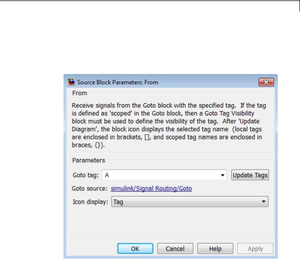
From
Data Type
Support
Parameters and Dialog Box
The From block outputs real or complex signals of any data type that Simulink supports, including fixed-point and enumerated data types.
For more information, see “Data Types Supported by Simulink” in the Simulink documentation.
Goto Tag
The tag of the Goto block that forwards its signal to this From block. To change the tag, select a new tag from this control’s drop-down list. The drop-down list displays the Goto tags that the From block can currently see. An item labeled <More Tags...> appears at the end of the list the first time you display the list in a Simulink session. Selecting this item causes the block to update
2-659

From
the tags list to include the tags of Goto blocks residing in library subsystems referenced by the model containing this From block. Simulink software displays a progress bar while building the list of library tags. Simulink software saves the updated tags list for the duration of the Simulink session or until the next time you select the adjacent Update Tags button. You need to update the tags list again in the current session only if the libraries referenced by the model have changed since the last time you updated the list.
Update Tags
Updates the list of tags visible to this From block, including tags residing in libraries referenced by the model containing this From block.
Goto Source
Path of the Goto block connected to this From block. Clicking the path displays and highlights the Goto block.
Icon Display
Specifies the text to display on the From block’s icon. The options are the block’s tag, the name of the signal that the block represents, or both the tag and the signal name.
Examples The following models show how to use the From block:
•sldemo_auto_climatecontrol
•sldemo_hardstop
Characteristics |
Sample Time |
Inherited from the block driving the |
|
|
Goto block |
|
Dimensionalized |
Yes |
|
Multidimensionalized |
Yes |
|
|
|
2-660

From
|
|
Virtual |
Yes |
|
|
|
For more information, see |
|
|
|
“Virtual Blocks” in the Simulink |
|
|
|
documentation. |
|
|
Zero-Crossing Detection |
No |
See Also |
|
Goto |
|
2-661

From File
Purpose |
Read data from MAT-file |
Library Sources
Description The From File block reads data from a MAT-file and outputs the data as a signal. The data is a sequence of samples. Each sample consists of a time stamp and an associated data value.
The From File block icon shows the name of the MAT-file that supplies the data.
You can have multiple From File blocks that read from the same MAT-file.
During the current simulation, the From File block cannot read data from a MAT-file that is being written to by a To File block.
Version 7.3 MAT-Files
For a Version 7.3 MAT-file, the From File block incrementally reads data from the MAT-file during simulation. The Sample time parameter specifies the sample time that the From File block uses to read data from a MAT-file. For details, see “Parameters and Dialog Box”.
The time stamps in the file must be monotonically nondecreasing.
For each simulation time hit for which the MAT-file contains no matching time stamp, Simulink software interpolates or extrapolates to obtain the needed data using the method that you select. For details, see “Simulation Time Hits That Have No Corresponding MAT-File Time Stamps.”
When the From File block reads data from a MAT-file, that data must be stored in one of two formats:
•MATLAB timeseries object
•Array
2-662
From File
Use array format only for vector, double, noncomplex signals. To load a bus signal, use a MATLAB structure that matches the bus hierarchy, where each leaf of the structure is a MATLAB timeseries object.
MATLAB timeseries format data can have:
•Any dimensionality and complexity
•Any built-in data type, including Boolean
•A fixed-point data type with a word length of up to 32 bits
•An enumerated data type
For the array format, the stored data is a matrix containing two or more rows. The matrix in the MAT-file must have the following form:
|
t1 |
t2 |
|
tfinal |
|
|
u1 |
u1 |
u1 |
|
|
||
|
1 |
2 |
|
|
final |
|
|
|
|
|
|
|
|
|
|
un2 |
|
|
|
|
un1 |
unfinal |
|||||
|
|
|
|
|
|
|
The first element of each column contains a time stamp. The remainder of the column contains data for the corresponding output values.
For data stored using the array format, the width of the From File output depends on the number of rows in the matrix. Given a matrix containing m rows, the block outputs a vector of length m–1.
Version 7.0 and Earlier Version MAT-Files
For Version 7.0 or an earlier version of a MAT-file, the From File block reads only array-format data. The complete, uncompressed data from a MAT-file loads into memory at the start of the simulation.
If you have a Version 7.0 or earlier version MAT-file that you want to use with the From File block, consider converting the file to a Version 7.3 MAT-file. Use a Version 7.3 MAT-file if you want the From File block to incrementally read the data during simulation or you want to use MATLAB timeseries data. For example, to convert a Version 7.0
2-663

From File
file named my_data_file.mat that contains the variable var, at the MATLAB command line, enter:
load('my_data_file.mat') save('my_data_file.mat', 'var', '-v7.3')
Simulation Time Hits That Have No Corresponding MAT-File Time Stamps
If the simulation time hit does not have a corresponding MAT-file time stamp, then the From File block output depends on:
•The location of the simulation time hit relative to the time stamps in the MAT-file
•The interpolation or extrapolation methods that you select
•The data type of the MAT-file data
For details about interpolation and extrapolation options, see the descriptions of the following parameters in “Parameters and Dialog Box”:
•Data extrapolation before first data point
•Data interpolation within time range
•Data extrapolation after last data point
Sometimes the MAT-file includes duplicate time stamps (two or more data values that have the same time stamp). In such cases, the From File block action depends on the location of the simulation time hit, relative to the duplicate time stamps in the MAT-file.
For example, suppose the MAT-file contains the following data, with three data points having a time stamp value of 2:
time stamps: 0 1 2 2 2 3 4 data values: 2 3 6 4 9 1 5
The following table describes the From File block output.
2-664

From File
|
Simulation Time, Relative to |
From File Block Action |
|
|
Duplicate Time Stamp Values |
|
|
|
in MAT-File |
|
|
|
Before the duplicate time stamps |
Performs the same actions |
|
|
|
as when the time stamps are |
|
|
|
distinct, using the first of the |
|
|
|
duplicate time stamp values as |
|
|
|
the basis for interpolation. (In |
|
|
|
this example, that time stamp |
|
|
|
value is 6.) |
|
|
At or after the duplicate time |
Performs the same actions as |
|
|
stamps |
when the times stamps are |
|
|
|
distinct, using the last of the |
|
|
|
duplicate time stamp values as |
|
|
|
the basis for interpolation. (In |
|
|
|
this example, that time stamp |
|
|
|
value is 9.) |
|
Using Data Saved by a To File Block
The From File block reads data written by a To File block without any modifications to the data or other special provisions.
Using Bus Data
The From File block supports loading nonvirtual bus signals.
The data must be in a MATLAB structure that matches the bus hierarchy. Each leaf of the structure must be a MATLAB timeseries object.
The data can underspecify the bus signal, but cannot overspecify the bus signal. The structure cannot have any elements that do not have corresponding signals in the bus.
The structure does not require data for every element in the bus hierarchy, but the structure must have data for at least one of the signals in the bus. For signals that do not specify data, the From File block outputs the ground values. If any data read by the From
2-665

From File
Data Type
Support
File block has variable dimensions, then you must specify data for all complex bus signals.
The From File block can read real or complex signal data of any data type that Simulink supports, except that fixed-point data cannot have a word length that exceeds 32 bits.
The From File block supports reading nonvirtual bus signals.
2-666
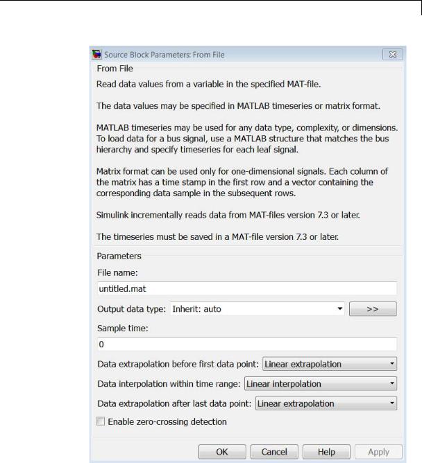
From File
Parameters and Dialog Box
File name
The path or file name of the MAT-file that contains the data used as input. On UNIX® systems, the path name can start with a tilde
2-667

From File
(~) character signifying your home folder. The default file name is untitled.mat. If you specify a file name without path information, Simulink reads the file in the MATLAB working folder. (To determine the working folder, type pwd at the MATLAB command line.) If Simulink cannot find the specified file name in the working folder, it displays an error message.
Output data type
The data type for the data that the From File block loads. For non-bus types, you can use Inherit: auto to skip any data type verification. If you specify an output data type, then the From File block verifies that the data in the file matches the data type that you specified. For more information, see “Specify Block Output Data Types”.
If you set Output data type to be a bus object, the bus object must be available when you compile the model. For each signal in a bus, the From File block verifies that the data type, dimension, and complexity of the data matches the data type, dimension, and complexity that the bus object defines for the signal.
•Inherit: auto — Default
•double
•single
•int8
•uint8
•int16
•uint16
•int32
•uint32
•boolean
•fixdt(1,16,0) — Data type is fixed-point (1,16,0).
•fixdt(1,16,2^0,0) — Data type is fixed-point (1,16,2^0,0).
2-668

From File
•Enum: <class_name> — Data type is enumerated.
•Bus: <bus_object> — Data type is a bus object. For details, see the “Using Bus Data” section.
•<data type expression> — The name of a data type object, for example Simulink.NumericType. Do not specify a bus object as the expression.
>> (Show data type assistant)
Displays the Data Type Assistant, to help you to set the Output data type parameter.
Mode
The category of data to specify. For more information, see “Specify Block Output Data Types”.
•Inherit — Inheritance rule for data types. Selecting Inherit enables a second menu/text box to the right. (Default)
•Built in — Built-in data types. Selecting Built in enables a second menu/text box to the right. Select one of the following choices:
-double — Default
-single
-int8
-uint8
-int16
-uint16
-int32
-uint32
-boolean
-Fixed point — Fixed-point data types
2-669

From File
-Enumerated — Enumerated data types. Selecting Enumerated enables a second menu/text box to the right, where you can enter the class name.
-Bus — Bus object. Selecting Bus enables a Bus object parameter to the right, where you enter the name of a bus object that you want to use to define the structure of the bus. If you need to create or change a bus object, click Edit to the right of the Bus object field to open the Simulink Bus Editor. For details, see “Manage Bus Objects with the Bus Editor”.
-Expression — Expression that evaluates to a data type. Selecting Expression enables a second menu/text box to the right, where you enter the expression. Do not specify a bus object as the expression.
Sample time
The sample period and offset of the data read from the file.
The From File block reads data from a MAT-file using a sample time that:
•You specify for the From File block
•The From File block inherits from the blocks into which the From File block feeds data
The default is 0, which specifies a continuous sample time, The MAT-file is read at the base (fastest) rate of the model. For details, see “Specify Sample Time”.
Data extrapolation before first data point
Extrapolation method that Simulink uses for a simulation time hit that is before the first time stamp in the MAT-file. Choose one of the following extrapolation methods.
2-670

From File
|
Method |
Description |
|
|
Linear |
(Default) |
|
|
extrapolation |
If the MAT-file contains only one sample, then |
|
|
|
|
|
|
|
the From File block outputs the corresponding |
|
|
|
data value. |
|
|
|
If the MAT-file contains more than one sample, |
|
|
|
then the From File block linearly extrapolates |
|
|
|
using the first two samples: |
|
|
|
• For double data, linearly extrapolates the |
|
|
|
value using the first two samples |
|
|
|
• For Boolean data, outputs the first data |
|
|
|
value |
|
|
|
• For a built-in data type other than double |
|
|
|
or Boolean, upcasts the data to double, |
|
|
|
performs linear extrapolation (as described |
|
|
|
above for double data), and then downcasts |
|
|
|
the extrapolated data value to the original |
|
|
|
data type |
|
|
|
You cannot use the Linear extrapolation |
|
|
|
option with enumerated (enum) data. All signals |
|
|
|
in a bus use the same extrapolation setting, so |
|
|
|
if any signal in a bus uses enum data, then you |
|
|
|
cannot use the Linear extrapolation option. |
|
|
Hold first value |
Uses the first data value in the file |
|
|
Ground value |
Uses a value that depends on the data type of |
|
|
|
MAT-file sample data values: |
|
|
|
• Fixed-point data types — uses the ground |
|
|
|
value |
|
|
|
• Numeric types other than fixed–point — |
|
|
|
uses 0 |
|
|
|
|
|
2-671

From File
Method Description
•Boolean — uses false
•Enumerated data types — uses default value
Data interpolation within time range
The interpolation method that Simulink uses for a simulation time hit between two time stamps in the MAT-file. Choose one of the following interpolation methods.
|
Method |
Description |
|
|
Linear |
(Default) |
|
|
interpolation |
The From File block interpolates using the two |
|
|
|
|
|
|
|
corresponding MAT-file samples: |
|
|
|
• For double data, linearly interpolates the |
|
|
|
value using the two corresponding samples |
|
|
|
• For a built-in data type other than double |
|
|
|
or Boolean, upcasts the data to double, |
|
|
|
performs linear interpolation (as described |
|
|
|
above for double data), and then downcasts |
|
|
|
the interpolated value to the original data |
|
|
|
type |
|
|
|
You cannot use the Linear interpolation |
|
|
|
option with enumerated (enum) data. All signals |
|
|
|
in a bus use the same interpolation setting, so |
|
|
|
if any signal in a bus uses enum data, then you |
|
|
|
cannot use the Linear interpolation option. |
|
|
Zero order hold |
Uses the data from the first of the two samples |
|
|
|
|
|
2-672
From File
Data extrapolation after last data point
The extrapolation method that Simulink uses for a simulation time hit that is after the last time stamp in the MAT-file. Choose one of the following extrapolation methods.
|
Method |
Description |
|
|
Linear |
(Default) |
|
|
extrapolation |
If the MAT-file contains only one sample, then |
|
|
|
|
|
|
|
the From File block outputs the corresponding |
|
|
|
data value. |
|
|
|
If the MAT-file contains more than one sample, |
|
|
|
then the From File block linearly extrapolates |
|
|
|
using data values of the last two samples: |
|
|
|
• For double data, extrapolates the value |
|
|
|
using the last two samples |
|
|
|
• For Boolean data, outputs the last data |
|
|
|
value |
|
|
|
• For a built-in data type other than double |
|
|
|
or Boolean, upcasts the data to double, |
|
|
|
performs linear extrapolation (as described |
|
|
|
above for double data), and then downcasts |
|
|
|
the extrapolated value to the original data |
|
|
|
type |
|
|
|
You cannot use the Linear extrapolation |
|
|
|
option with enumerated (enum) data. All signals |
|
|
|
in a bus use the same extrapolation setting, so |
|
|
|
if any signal in a bus uses enum data, then you |
|
|
|
cannot use the Linear extrapolation option. |
|
|
Hold last value |
Uses the last data value in the file |
|
|
Ground value |
Uses a value that depends on the data type of |
|
|
|
MAT-file sample data values: |
|
|
|
|
|
2-673

From File
Method Description
•Fixed-point data types — uses the ground value
•Numeric types other than fixed–point — uses 0
•Boolean — uses false
•Enumerated data types — uses default value
Enable zero-crossing detection
Select to enable zero-crossing detection.
For details, see “Zero-Crossing Detection”, as well as the discussion below.
Simulink uses a technique known as zero-crossing detection to accurately locate a discontinuity, without resorting to excessively small time steps. This section uses “zero-crossing” to represent discontinuities.
For the From File block, zero-crossing detection can only occur at sample points in the file. To determine whether zero crossing occurs, the From File block examines only the time stamps within the sample points.
If the input array contains duplicate time stamps (more than one entry for the same time stamp), Simulink detects a zero crossing at that time stamp. For example, suppose the input array has this data:
time: 0 1 2 2 3 signal: 2 3 4 5 6
At time 2, there is a zero crossing from the input signal discontinuity.
For data with nonduplicate time stamps, zero-crossing detection depends on the settings of the following parameters:
• Data extrapolation before first data point
2-674

From File
•Data interpolation within time range
•Data extrapolation after last data point
The From File block applies the following rules when determining when zero-crossing occurs for the first time stamp, for time stamps between the first and last time stamp, and for the last time stamp.
|
Time Stamp |
When Zero-Crossing Detection Occurs |
|
|
First |
Data extrapolation before first data point is set |
|
|
|
to Ground value. |
|
|
Between first |
Data interpolation within time range is set to |
|
|
and last |
Zero-order hold. |
|
|
Last |
One or both of these settings occur: |
|
|
|
• Data extrapolation after last data point is set |
|
|
|
to Ground value. |
|
|
|
• Data interpolation within time range is set to |
|
|
|
Zero-order hold. |
|
The following figure illustrates zero-crossing detection for data accessed by a From File block that has the following settings:
•Data extrapolation before first data point — Linear extrapolation
•Data interpolation within time range (for internal points) —
Zero order hold
•Data extrapolation after last data point — Linear extrapolation
2-675
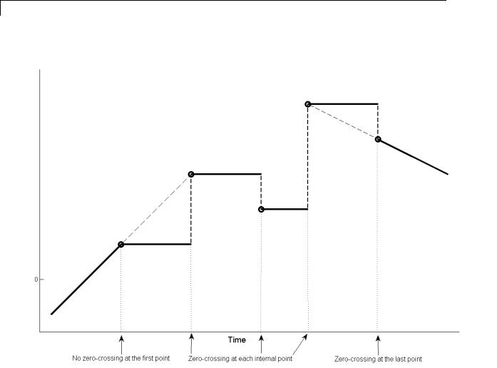
From File
The following figure is another illustration of zero-crossing detection for data accessed by a From File block. The block has the following settings for the time stamps (points):
•Data extrapolation before first data point — Hold first value
•Data interpolation within time range — Zero order hold
•Data extrapolation after last data point — Hold last value
2-676
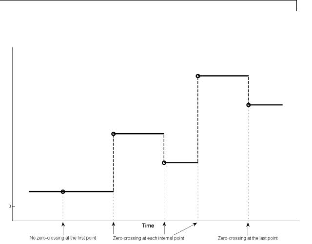
From File
Characteristics |
Sample Time |
Specified in the Sample time |
|
|
parameter |
|
Scalar Expansion |
No |
|
Dimensionalized |
Yes |
|
Zero Crossing |
Yes, if enabled |
|
|
|
2-677

From File
See Also |
“Import Data”, From Workspace, To File, To Workspace |
2-678

From Workspace
Purpose |
Read data from workspace |
Library Sources
Description The From Workspace block reads data from a workspace and outputs the data as a signal.
The From Workspace icon displays the expression specified in the Data parameter. For details about how Simulink software evaluates this expression, see “Symbol Resolution”.
Specifying the Workspace Data
In the Data parameter of the block, enter a MATLAB expression that specifies the workspace data. The expression must evaluate to one of the following:
•A MATLAB timeseries object
•A structure of MATLAB timeseries objects
•An array or structure containing an array of simulation times and corresponding signal values
The format of a MATLAB timeseries object, matrix, or structure loaded (imported) by a From Workspace block is the same as that used to load root-level input port data from the workspace.
•To load any non-bus data from the workspace, use a MATLAB timeseries object or a structure with time. For guidelines on choosing time vectors for discrete systems, see “Techniques for Importing Signal Data”.
•To load bus data, use a structure of MATLAB timeseries objects. For details, see “Import Structures of timeseries Objects for Buses”.
2-679

From Workspace
Using Data Saved by a To File Block
You can use the From Workspace block to load MATLAB timeseries object data that was saved by a To File block, without making any changes to the data.
To use the From Workspace block to load Array format data, before the From Workspace block loads the data that a To File block saved, transpose the array data. The data saved by the To File block contains consecutive time stamps at the beginnings of columns, followed by the corresponding data. The transposed data contains consecutive time stamps at the beginning of rows, followed by the corresponding data. To provide the required format, use MATLAB load and transpose commands with the MAT-file (see “Reshaping a Matrix”). To avoid having to transpose the data again later, resave the transposed data for future use.
Using Data Saved by a To Workspace Block
To use the From Workspace block to load data exported by a To Workspace block in a previous simulation for use in a later simulation, save the To Workspace block data in either Timeseries or Structure with Time format. For details, see “Techniques for Importing Signal Data”.
Loading Variable-Size Signals
You can use a To Workspace block (with Structure or Structure With Time format) or a root Outport block to log variable-size signals. You can then use the To Workspace variable with the From Workspace block.
Alternatively, you can create a MATLAB structure to contain variable-size signal data. For each values field in the structure, include a valueDimensions field that specifies the run-time dimensions for the signal. For details, see Simulink Models Using Variable-Size Signals.
Interpolating Missing Data Values
If you select the Interpolate data option, the block uses linear Lagrangian interpolation to compute data values for time steps that occur between time steps for which the workspace supplies data.
2-680

From Workspace
Data Type
Support
For variable-size signals, clear Interpolate data.
Specifying Output After Final Data
Combine the settings of the Form output after final data value by and Interpolate data parameters to determine the block output after the last time step for which workspace data is available. For details, see the Form output after final data value by parameter.
Detecting Zero Crossings
The Enable zero-crossing detection parameter applies only if the sample time is continuous (0).
If you select the Enable zero-crossing detection parameter, and if the input array contains more than one entry for the same time step, Simulink detects a zero crossing at that time step.
For bus signals, Simulink detects zero crossings across all leaf bus elements.
The From Workspace block accepts data from the workspace and outputs real or complex signals of any type supported by Simulink, including fixed-point and enumerated data types.
The From Workspace block also accepts a bus object as a data type. To load bus data, use a structure of MATLAB timeseries objects. For details, see “Import Structures of timeseries Objects for Buses”.
Real signals of type double can be in any format that the From Workspace block supports. For complex signals and real signals of a data type other than double, use any format except Array.
2-681
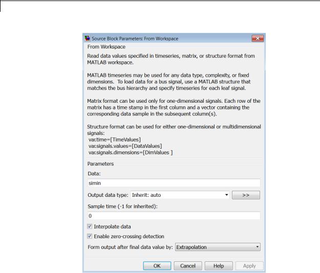
From Workspace
Parameters |
|
|
and |
Data |
|
Dialog |
||
A MATLAB expression that evaluates to one of the following: |
||
Box |
||
|
• A MATLAB timeseries object |
|
|
• A structure of MATLAB timeseries objects |
2-682
From Workspace
To load bus data, use a structure of MATLAB timeseries objects. For details, see “Import Structures of timeseries Objects for Buses”.
•A two-dimensional matrix:
-The first element of each matrix row is a time stamp.
-The rest of each row is a scalar or vector of signal values.
The leftmost element of each row is the time stamp of the value(s) in the rest of the row.
•A structure, with or without time, which contains:
-An array or matrix named signals.values, which contains scalars or vectors of signal values.
-An array named signals.dimensions, which contains the dimensions of the signals.
-Optionally, a vector named time, which contains time stamps.
The n’th time element is the time stamp of the n’th signals.values element. For details, see “Techniques for Importing Signal Data”.
For example, suppose that the workspace contains a column vector of times named T and a column vector of corresponding signal values named U. Entering the expression [T U] for this parameter yields the required input array. If the required array or structure already exists
in the workspace, enter the name of the structure or matrix in this field.
Output data type
The required data type for the data for the workspace variable that the From Workspace block loads. For non-bus types, you can use Inherit: auto to skip any data type verification. For more information, see “Specify Block Output Data Types”.
To load bus data, use a structure of MATLAB timeseries objects. For details, see “Import Structures of timeseries Objects for Buses”.
• Inherit: auto — Default.
2-683

From Workspace
•double
•single
•int8
•uint8
•int16
•uint16
•int32
•uint32
•boolean
•fixdt(1,16,0) — Data type is fixed-point (1,16,0).
•fixdt(1,16,2^0,0) — Data type is fixed-point (1,16,2^0,0).
•Enum: <class_name> — Data type is enumerated, for example,
Enum: Basic Colors.
•Bus: <bus_object> — Data type is a bus object.
•<data type expression> — The name of a data type object, for example Simulink.NumericType. Do not specify a bus object as the expression.
>> (Show data type assistant)
Displays the Data Type Assistant, to help you to set the Output data type parameter.
Mode
The category of data to specify. For more information, see “Specify Block Output Data Types”.
•Inherit — Inheritance rule for data types. Selecting Inherit enables a second menu/text box to the right. (Default)
•Built in — Built-in data types. Selecting Built in enables a second menu/text box to the right. Select one of the following choices:
2-684

From Workspace
-double — Default
-single
-int8
-uint8
-int16
-uint16
-int32
-uint32
-boolean
-Fixed point — Fixed-point data types
-Enumerated — Enumerated data types. Selecting Enumerated enables a second menu/text box to the right, where you can enter the class name.
-Bus — Bus object. Selecting Bus enables a Bus object parameter to the right, where you enter the name of a bus object that you want to use to define the structure of the bus. If you need to create or change a bus object, click Edit (to the right of the Bus object field) to open the Simulink Bus Editor. For details, see “Manage Bus Objects with the Bus Editor”.
-Expression — Expression that evaluates to a data type. Selecting Expression enables a second menu/text box to the right, where you enter the expression. Do not specify a bus object as the expression.
Sample time
Sample rate of data from the workspace. For details, see “Specify Sample Time”.
Interpolate data
Select this option to have the block linearly interpolate at time steps for which no corresponding workspace data exists. Otherwise, the current output equals the output at the most recent time for which data exists.
2-685

From Workspace
If you select this option, the block linearly interpolates a missing data point from the two known data points between which it falls. For example, suppose the block reads the following time series from the workspace:
time: |
1 |
2 |
3 |
4 |
signal: |
253 |
254 |
? |
256 |
The block would output: |
|
|||
time: |
1 |
2 |
3 |
4 |
signal: |
253 |
254 |
255 |
256 |
If you clear the Interpolate data option, the block uses the most recent data value supplied from the workspace to provide any missing data values. For example, the result of the incomplete set of signal values shown above would be:
time: 1 2 3 4 signal: 253 254 254 256
Integer data — If the input data type is an integer type and an interpolated data point exceeds the data type’s range, the block sets the missing data point to be the maximum value that the data type can represent. Similarly, if the interpolated or extrapolated value is less than the minimum value that the data type can represent, the block sets the missing data point to the minimum value that the data type can represent. For example, suppose that the data type is uint8 and the value interpolated for a missing data point is 256.
time: 1 2 3 4 signal: 253 254 255 ?
In this case, the block sets the value of the missing point to 255, the largest value that can be represented by the uint8 data type:
time: 1 2 3 4 signal: 253 254 255 255
2-686

From Workspace
Boolean data — If the input data is boolean, the block uses the value of the nearest workspace data point as the value of missing data point when determining missing data points that fall between the first and last known points. For example, suppose the workspace supplies values at time steps 1 and 4 but not at 2 and 3:
time: 1 2 3 4 signal: 1 ? ? 0
In this case, the block would use the value of data point 1 as the value of data point 2 and the value of data point 4 as the value of data point 3:
time: 1 2 3 4 signal: 1 1 0 0
The block uses the value of the last known data point as the value of time steps that occur after the last known data point.
Combine the settings of the Interpolate data and Form output after final data value by parameters to determine the block output after the last time step for which workspace data is available. For details, see the Form output after final data value by parameter.
Enable zero-crossing detection
If you select the Enable zero-crossing detection parameter, then when the input array contains more than one entry for the same time step, Simulink detects a zero crossing at that time step. For example, suppose the input array has this data:
time: 0 1 2 2 3 signal: 2 3 4 5 6
At time 2, there is a zero crossing from input signal discontinuity. For more information, see “Zero-Crossing Detection”.
For bus signals, Simulink detects zero crossings across all leaf bus elements.
2-687

From Workspace
Form output after final data value by
Combine the settings of the Form output after final data value by and Interpolate data parameters to determine the block output after the last time step for which workspace data is available. The following table describes the block output based on the values of the two options:
|
Setting for Form |
Setting for |
|
|
|
Output After Final |
Interpolate |
Block Output After Final |
|
|
Data Value By |
Data |
Data |
|
|
Extrapolation |
On |
Extrapolated from final data |
|
|
|
|
value |
|
|
|
Off |
Error |
|
|
Setting to zero |
On |
Zero |
|
|
|
|
|
|
|
|
Off |
Zero |
|
|
Holding final value |
On |
Final value from workspace |
|
|
|
Off |
Final value from workspace |
|
|
Cyclic repetition |
On |
Error |
|
|
|
Off |
Repeated from workspace |
|
|
|
|
if the workspace data is |
|
|
|
|
in structure-without-time |
|
|
|
|
format. Error otherwise. |
|
For example, if Form output after final data value by is
Extrapolation and Interpolate data is selected, the block uses the last two known data points to extrapolate data points that occur after the last known point. Consider the following model.
2-688

From Workspace
In this model, the From Workspace block reads data from the workspace consisting of the output of the Simulink Sine block sampled at one-second intervals. The workspace contains the first 16 samples of the output. The top and bottom X-Y plots display the output of the Sine Wave and From Workspace blocks, respectively, from 0 to 20 seconds. The straight line in the output of the From Workspace block reflects the block’s linear extrapolation of missing data points at the end of the simulation.
Examples The From Workspace block allows you to read 1-D and 2-D signals into Simulink.
2-689

From Workspace
Reading 1-D Signals in Array Format
Create two signals x and y with a time vector t, and then import the values into Simulink with an array.
1In the MATLAB Command Window, enter
t= [0:0.2:10]';
x= sin(t);
y= 10*sin(t);
The time vector must be a column vector.
2Add a From Workspace block to your model.
3Double-click the block to open the block parameters dialog. In the Data field, enter the array [t,x,y],
Reading 1-D Signals in Structure Format
Create two signals x and y with a time vector t, and then import the values into Simulink with a structure.
1In the MATLAB Command Window, enter
t= [0:0.2:10]';
x= sin(t);
y= 10*sin(t);
wave.time = t; wave.signals.values = [x,y]; wave.signals.dimensions =2;
The time vector must be a column vector. The signals.dimensions field for a 1-D signal is a scalar corresponding to the number of signals or number of columns in the signals.values field. Each column in the signals.values field corresponds to a signal
2 Add a From Workspace block to your model.
2-690

From Workspace
Using
Sample Time from Model
3Double-click the block to open the block parameters dialog. In the Data field, enter the structure name.
If you do not have a time vector, you can define the sample time in your model.
1In the MATLAB Command Window, enter wave.time = [];
2Double-click the From Workspace block to open the block parameters dialog. In the Sample time field, enter a time interval. For example, enter 0.2. Clear the Interpolate data check box.
From the Form output after final data value by, select either
Setting to zero, Holding final value, or Cyclic repetition. Do not select Extrapolation.
Reading 2-D Signals in Structure Format
To load 2-D signals from the MATLAB workspace into Simulink, you must have the signals in a structure format. This example creates a 10–by–10 matrix (2-D signal) using the magic function, and then creates a 3-D matrix by adding a time vector.
1In the MATLAB Command Window, enter
t1 = [0:0.2:10]'; m = magic(10);
M = repmat(m,[1 1 length(t1)]); data.time=t1; data.signals.values = M; data.signals.dimensions=[10 10];
2-691

From Workspace
The time vector must be a column vector. The signals.values field is a 3-D matrix where the third dimension is the signal values at a specific time. The signals.dimensions field is a two element vector where the first element is the number of rows and the second element is the number of columns in the signals.values field.
2Double-click the From Workspace block to open the block parameters dialog. In the Data field, enter the name of the structure.
Characteristics |
|
Sample Time |
Specified in the Sample time |
|
|
|
parameter |
|
|
Scalar Expansion |
No |
|
|
Dimensionalized |
Yes |
|
|
Multidimensionalized |
Yes |
|
|
Zero-Crossing Detection |
Yes, if enabled. |
See Also |
|
“Import Data”, “Import Data for an Input Test Case”, From File, To |
|
|
|
File, To Workspace |
|
2-692
Function-Call Feedback Latch
Purpose
Library
Description
Break feedback loop involving data signals between function-call blocks
Ports & Subsystems
Use the Function-Call Feedback Latch block to break a feedback loop of data signals between one or more function-call blocks. Specifically, break a loop formed in one of the following ways.
•When function-call blocks connect to branches of the same function-call signal
Place the Function-Call Feedback Latch block on the feedback signal between the branched blocks. As a result, the latch block delays the signal at the input of the destination function-call block, and the destination function-call block executes prior to the source function-call block of the latch block.
•When the loop involves parent and child function-call blocks, where the child initiator is inside the parent
Place the Function-Call Feedback Latch block on the feedback signal between the child and the parent. This arrangement prevents the
2-693
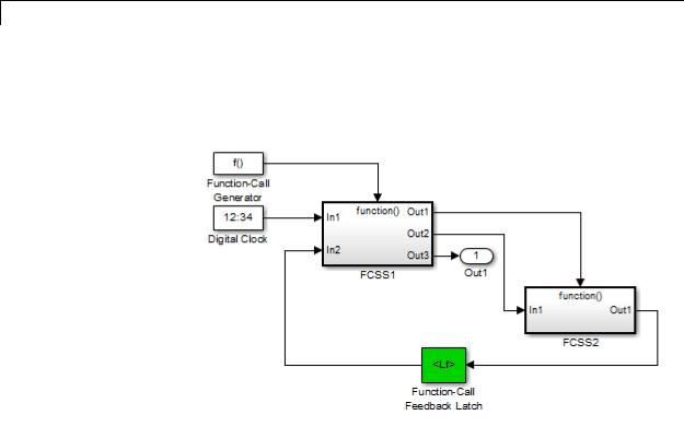
Function-Call Feedback Latch
signal value, read by the parent (FCSS1), from changing during execution of the child. In other words, the parent reads the value from the previous execution of the child (FCSS2).
Using the latch block is equivalent to selecting the Latch input for function-call feedback signals check box on the Inport block in the destination function-call subsystem. However, an advantage of the latch block over the dialog parameter is that one can design the
destination function-call subsystem (or model) in a modular fashion and then use it either in or out of the context of loops.
The Function-Call Feedback Latch block is better suited than the Unit Delay or Memory blocks in breaking function-call feedback loops for the following reasons:
•The latch block delays the feedback signal for exactly one execution of the source function-call block. This behavior is different from the Unit Delay or Memory blocks for cases where the function-call subsystem blocks may execute multiple times in a given simulation step.
2-694

Function-Call Feedback Latch
Data Type
Support
•Unlike the Unit Delay or Memory blocks, the latch block may be used to break loops involving asynchronous function-call subsystems.
•The latch block can result in better performance, in terms of memory optimization, for generated code.
The Function-Call Feedback Latch block accepts real or complex signals of the following data types:
•Floating point
•Built-in integer
•Fixed point
•Boolean
•Enumerated
In addition, the latch block accepts bus signals provided that they do not contain any variable-sized signals.
This block does not accept:
•Function-call signals
•Action signals
•Variable-sized signals
For more information, see “Data Types Supported by Simulink” in the Simulink documentation.
2-695
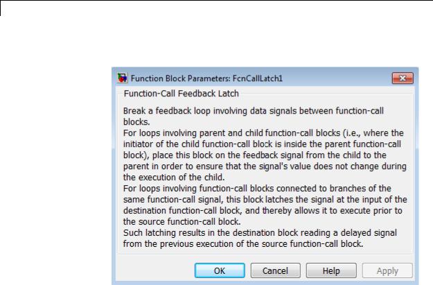
Function-Call Feedback Latch
Parameters The Function-Call Feedback Latch block dialog box appears as follows:
and Dialog Box
Examples In the following model, a single function-call subsystem output serves as its own input.
2-696
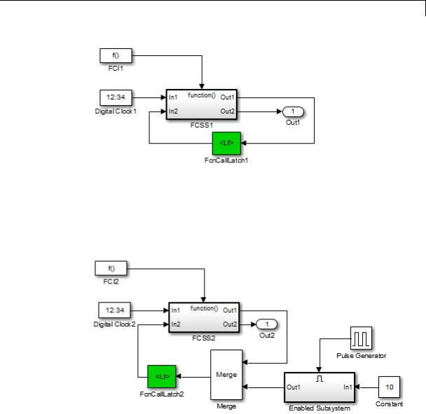
Function-Call Feedback Latch
A more complex case occurs when a merged signal serves as the input to a function-call subsystem. Latching is necessary if one of the signals entering the Merge block forms a feedback loop with the function-call subsystem. In this example, one of the output signals from FCSS2 combines with the output of an Enabled Subsystem block and then feeds back into an inport of FCSS2.
2-697

Function-Call Feedback Latch
Characteristics |
|
Direct Feedthrough |
No |
|
|
Sample Time |
Inherited from the driving block |
|
|
Scalar Expansion |
Yes |
|
|
Dimensionalized |
Yes |
|
|
Multidimensionalized |
Yes |
|
|
Zero-Crossing Detection |
No |
See Also |
|
Function-Call Subsystem block |
|
2-698

Function-Call Generator
Purpose |
Execute function-call subsystem specified number of times at specified |
|
rate |
Library |
Ports & Subsystems |
Description |
The Function-Call Generator block executes a function-call subsystem |
|
(for example, a Stateflow chart acting as a function-call subsystem) |
|
at the rate that you specify with the Sample time parameter. To |
|
iteratively execute each function-call block connected to this block |
|
multiple times at each time step, use the ‘Number of Iterations’ |
|
parameter. |
|
To execute multiple function-call subsystems or models in a prescribed |
|
order, use the Function-Call Generator block in conjunction with a |
|
Function-Call Split block. For an example, see the Function-Call Split |
|
block documentation. |
Data Type
Support
The Function-Call Generator block outputs a signal of type fcn_call.
2-699
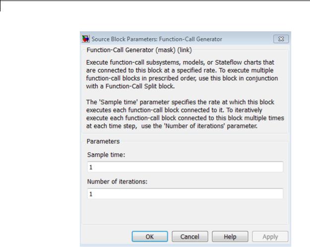
Function-Call Generator
Parameters and Dialog Box
Sample time
Specify the time interval between samples. See “Specify Sample Time” in the online documentation for more information.
Number of iterations
Number of times to execute the block per time step. The value of this parameter can be a vector where each element of the vector specifies a number of times to execute a function-call subsystem.
The total number of times that a function-call subsystem executes
2-700

Function-Call Generator
per time step equals the sum of the values of the elements of the generator signal entering its control port.
Suppose that you specify the number of iterations to be [2 2] and connect the output of this block to the control port of a function-call subsystem. In this case, the function-call subsystem executes four times at each time step.
Characteristics |
Direct Feedthrough |
No |
|
Sample Time |
Specified in the Sample time |
|
|
parameter |
|
Scalar Expansion |
No |
|
Dimensionalized |
Yes |
|
Zero-Crossing Detection |
No |
|
|
|
2-701

Function-Call Split
Purpose |
Provide junction for splitting function-call signal |
Library |
Ports & Subsystems |
Description |
The Function-Call Split block allows a function-call signal to be |
|
branched and connected to several function-call subsystems and models. |
|
Several Function-Call Split blocks may be cascaded one after another |
|
to create multiple branches for a function-call signal. An advantage |
|
of the Function-Call Split block is that in some cases, using this |
|
block eliminates the need for the initiator block to create multiple |
|
function-call signals for invoking a set of function-call subsystems or |
|
models. |
|
Function-call subsystems or models connected to the output port of |
|
the Function-Call Split block marked with a dot execute before the |
|
subsystems or models connected to the other output port. If any data |
|
dependencies between these subsystems (or between models) do not |
|
support the specified execution order, then an error occurs. This implies |
|
that an error will always occur when you create a data-dependency loop |
|
involving function-call subsystems or models connected to branches |
|
of the same function-call signal. To eliminate this error, consider |
|
turning on the Latch input for feedback signals of function-call |
|
subsystem outputs on one or more Inport blocks of the function-call |
|
subsystems (or models) involved in the loop. Setting this option to |
|
on has the effect of delaying the corresponding input signal, thereby |
|
eliminating the data-dependency loop. |
|
In order for a model to contain Function-Call Split blocks, you must set |
|
the following diagnostic to error: Model Configuration Parameters |
|
> Diagnostics > Connectivity > Invalid function-call connection. |
|
If you turn on the model option Format > Block Displays > Sorted |
|
Order, then the execution order of function-call subsystems connected |
|
to branches of a given function-call signal displays on the blocks . |
|
Each subsystem has an execution order of the form S:B#{C}. Here, # |
|
is a number that ranges from 0 to one less than the total number of |
|
subsystems (or models) connected to branches of a given signal. The |
|
subsystems execute in ascending order based on this number. |
2-702
Function-Call Split
Data Type
Support
The Function-Call Split block supports signal label propagation.
Limitations
The Function-Call Split block has these limitations:
Limitations
Triggered function-call signals cannot be branched. Only periodic and asynchronous function-call signals can be connected to the Function-Call Split block.
All function-call subsystems and models connected to a given function-call signal must reside within the same nonvirtual layer of the model hierarchy.
Branched function-call subsystems (or models) and their children cannot be connected directly back to the initiator.
Function-call subsystems and models connected to branches of a function-call signal cannot have multiple (muxed) initiators.
The Function-Call Split block accepts periodic and asynchronous function-call signals only.
2-703
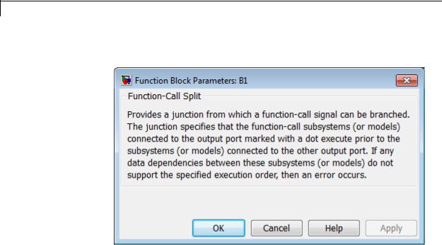
Function-Call Split
Parameters The Function-Call Split block dialog box appears as follows:
and Dialog Box
Examples The following model shows how to apply the Latch input for feedback signals of function-call subsystem outputs parameter to work around a data-dependency error caused by using a Function-Call Split block. By turning this parameter on in the f1 subsystem Inport block, the Function-Call Split block ignores the data dependency of signal b and thus breaks the loop of data dependencies between subsystems f1 and g1. The model thus achieves the desired behavior of consistently calling f1 to execute before g1. For a given execution step, subsystem f1 uses the g1 output computed at the previous execution step.
2-704
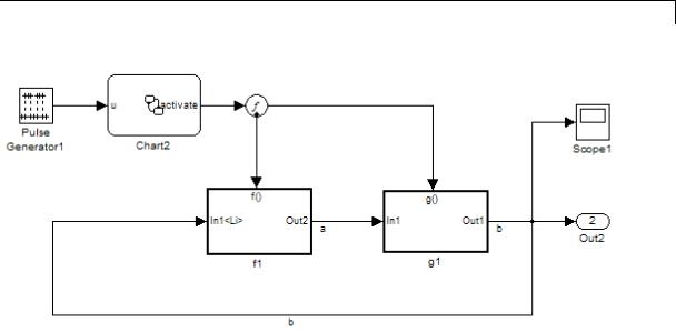
Function-Call Split
Characteristics |
|
Sample Time |
Inherited from the block driving |
|
|
|
the function-call split |
|
|
Scalar Expansion |
No |
|
|
Dimensionalized |
No |
|
|
Multidimensionalized |
No |
|
|
Virtual |
Yes |
See Also |
|
Function-Call Subsystem | Function-Call Generator |
|
2-705

Function-Call Subsystem
Purpose |
Represent subsystem that can be invoked as function by another block |
Library |
Ports & Subsystems |
Description |
|
The Function-Call Subsystem block is a Subsystem block that is preconfigured to serve as a starting point for creating a function-call subsystem. For more information, see “Function-Call Subsystems” in the “Creating a Model” chapter of the Simulink documentation.
2-706

Gain
Purpose |
Multiply input by constant |
Library |
Math Operations |
Description |
The Gain block multiplies the input by a constant value (gain). The |
|
input and the gain can each be a scalar, vector, or matrix. |
|
You specify the value of the gain in the Gain parameter. The |
|
Multiplication parameter lets you specify element-wise or matrix |
|
multiplication. For matrix multiplication, this parameter also lets you |
|
indicate the order of the multiplicands. |
|
The gain is converted from doubles to the data specified in the block |
|
mask offline using round-to-nearest and saturation. The input and gain |
|
are then multiplied, and the result is converted to the output data type |
|
using the specified rounding and overflow modes. |
Data Type |
The Gain block accepts a real or complex scalar, vector, or matrix of any |
Support |
numeric data type that Simulink supports. The Gain block supports |
|
fixed-point data types. If the input of the Gain block is real and the gain |
|
is complex, the output is complex. |
|
For more information, see “Data Types Supported by Simulink” in the |
|
Simulink documentation. |
2-707
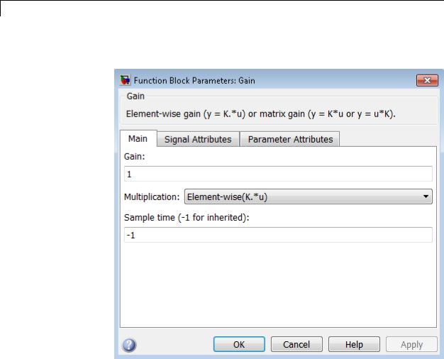
Gain
Parameters The Main pane of the Gain block dialog box appears as follows:
and Dialog Box
2-708

Gain
The Signal Attributes pane of the Gain block dialog box appears as follows:
2-709
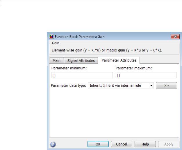
Gain
The Parameter Attributes pane of the Gain block dialog box appears as follows:
2-710

Gain
Gain
Specify the value by which to multiply the input.
Settings
Default: 1
Minimum: value of Parameter minimum parameter Maximum: value of Parameter maximum parameter
The gain can be a scalar, vector, or matrix.
Command-Line Information
See “Block-Specific Parameters” on page 8-109 for the command-line information.
2-711

Gain
Multiplication
Specify the multiplication mode.
Settings
Default: Element-wise(K.*u)
Element-wise(K.*u)
Each element of the input is multiplied by each element of the gain. The block performs expansions, if necessary, so that the input and gain have the same dimensions.
Matrix(K*u)
The input and gain are matrix multiplied with the input as the second operand.
Matrix(u*K)
The input and gain are matrix multiplied with the input as the first operand.
Matrix(K*u)(u vector)
The input and gain are matrix multiplied with the input as the second operand. This mode is identical to Matrix(K*u), except for how dimensions are determined.
Suppose that K is an m-by-n matrix. Matrix(K*u)(u vector) sets the input to a vector of length n and the output to a vector of length m. In contrast, Matrix(K*u) uses propagation to determine dimensions for the input and output. For an m-by-n gain matrix, the input can propagate to an n-by-q matrix, and the output becomes an m-by-q matrix.
Command-Line Information
See “Block-Specific Parameters” on page 8-109 for the command-line information.
2-712
Gain
Sample time (-1 for inherited)
Specify the time interval between samples.
Settings
Default: -1
To inherit the sample time, set this parameter to -1.
See “Specify Sample Time” in the online documentation for more information.
Command-Line Information
See “Block-Specific Parameters” on page 8-109 for the command-line information.
2-713

Gain
Output minimum
Specify the minimum value that the block should output.
Settings
Default: [] (unspecified)
This number must be a finite real double scalar value.
Note If you specify a bus object as the data type for this block, do not set the minimum value for bus data on the block. Simulink ignores this setting. Instead, set the minimum values for bus elements of the bus object specified as the data type. For information on the Minimum property of a bus element, see Simulink.BusElement.
Simulink uses the minimum to perform:
•Parameter range checking (see “Check Parameter Values”) for some blocks
•Simulation range checking (see “Signal Ranges”)
•Automatic scaling of fixed-point data types
Command-Line Information
See “Block-Specific Parameters” on page 8-109 for the command-line information.
2-714

Gain
Output maximum
Specify the maximum value that the block should output.
Settings
Default: [] (unspecified)
This number must be a finite real double scalar value.
Note If you specify a bus object as the data type for this block, do not set the maximum value for bus data on the block. Simulink ignores this setting. Instead, set the maximum values for bus elements of the bus object specified as the data type. For information on the Maximum property of a bus element, see Simulink.BusElement.
Simulink uses the maximum value to perform:
•Parameter range checking (see “Check Parameter Values”) for some blocks
•Simulation range checking (see “Signal Ranges”)
•Automatic scaling of fixed-point data types
Command-Line Information
See “Block-Specific Parameters” on page 8-109 for the command-line information.
2-715

Gain
Output data type
Specify the output data type.
Settings
Default: Inherit: Inherit via internal rule
Inherit: Inherit via internal rule
Simulink chooses a combination of output scaling and data type that requires the smallest amount of memory consistent with accommodating the calculated output range and maintaining the output precision of the block and with the word size of the targeted hardware implementation specified for the model. If the
Device type parameter on the Hardware Implementation configuration parameters pane is set to ASIC/FPGA, Simulink software chooses the output data type without regard to hardware constraints. Otherwise, Simulink software chooses the smallest available hardware data type capable of meeting the range and precision constraints. For example, if the block multiplies an input of type int8 by a gain of int16 and ASIC/FPGA is specified as the targeted hardware type, the output data type is sfix24. If Unspecified (assume 32-bit Generic), i.e., a generic 32-bit microprocessor, is specified as the target hardware, the output data type is int32. If none of the word lengths provided by
the target microprocessor can accommodate the output range, Simulink software displays an error message in the Simulation Diagnostics Viewer.
Inherit: Inherit via back propagation
Use data type of the driving block.
Inherit: Same as input
Use data type of input signal.
double
Output data type is double.
single
Output data type is single.
2-716

Gain
int8
Output data type is int8.
uint8
Output data type is uint8.
int16
Output data type is int16.
uint16
Output data type is uint16.
int32
Output data type is int32.
uint32
Output data type is uint32.
fixdt(1,16,0)
Output data type is fixed point fixdt(1,16,0).
fixdt(1,16,2^0,0)
Output data type is fixed point fixdt(1,16,2^0,0).
<data type expression>
Use a data type object, for example, Simulink.NumericType.
Command-Line Information
See “Block-Specific Parameters” on page 8-109 for the command-line information.
See Also
See “Specify Block Output Data Types” for more information.
2-717

Gain
Mode
Select the category of data to specify.
Settings
Default: Inherit
Inherit
Inheritance rules for data types. Selecting Inherit enables a second menu/text box to the right. Select one of the following choices:
•Inherit via internal rule (default)
•Inherit via back propagation
•Same as input
Built in
Built-in data types. Selecting Built in enables a second menu/text box to the right. Select one of the following choices:
•double (default)
•single
•int8
•uint8
•int16
•uint16
•int32
•uint32
Fixed point
Fixed-point data types.
Expression
Expressions that evaluate to data types. Selecting Expression enables a second menu/text box to the right, where you can enter the expression.
2-718

Gain
Dependency
Clicking the Show data type assistant button enables this parameter.
Command-Line Information
See “Block-Specific Parameters” on page 8-109 for the command-line information.
See Also
See “Specify Data Types Using Data Type Assistant”.
2-719

Gain
Data type override
Specify data type override mode for this signal.
Settings
Default: Inherit
Inherit
Inherits the data type override setting from its context, that is, from the block, Simulink.Signal object or Stateflow chart in Simulink that is using the signal.
Off
Ignores the data type override setting of its context and uses the fixed-point data type specified for the signal.
Tip
The ability to turn off data type override for an individual data type provides greater control over the data types in your model when you apply data type override. For example, you can use this option to ensure that data types meet the requirements of downstream blocks regardless of the data type override setting.
Dependency
This parameter appears only when the Mode is Built in or Fixed point.
2-720

Gain
Signedness
Specify whether you want the fixed-point data as signed or unsigned.
Settings
Default: Signed
Signed
Specify the fixed-point data as signed.
Unsigned
Specify the fixed-point data as unsigned.
Dependencies
Selecting Mode > Fixed point enables this parameter.
Command-Line Information
See “Block-Specific Parameters” on page 8-109 for the command-line information.
See Also
For more information, see “Specifying a Fixed-Point Data Type”.
2-721

Gain
Word length
Specify the bit size of the word that holds the quantized integer.
Settings
Default: 16
Minimum: 0
Maximum: 32
Dependencies
Selecting Mode > Fixed point enables this parameter.
Command-Line Information
See “Block-Specific Parameters” on page 8-109 for the command-line information.
See Also
For more information, see “Specifying a Fixed-Point Data Type”.
2-722
Gain
Scaling
Specify the method for scaling your fixed-point data to avoid overflow conditions and minimize quantization errors.
Settings
Default: Binary point
Binary point
Specify binary point location.
Slope and bias
Enter slope and bias.
Dependencies
Selecting Mode > Fixed point enables this parameter.
Selecting Binary point enables:
•Fraction length
•Calculate Best-Precision Scaling
Selecting Slope and bias enables:
•Slope
•Bias
•Calculate Best-Precision Scaling
Command-Line Information
See “Block-Specific Parameters” on page 8-109 for the command-line information.
See Also
See “Specifying a Fixed-Point Data Type”.
2-723

Gain
Fraction length
Specify fraction length for fixed-point data type.
Settings
Default: 0
Binary points can be positive or negative integers.
Dependencies
Selecting Scaling > Binary point enables this parameter.
Command-Line Information
See “Block-Specific Parameters” on page 8-109 for the command-line information.
See Also
For more information, see “Specifying a Fixed-Point Data Type”.
2-724

Gain
Slope
Specify slope for the fixed-point data type.
Settings
Default: 2^0
Specify any positive real number.
Dependencies
Selecting Scaling > Slope and bias enables this parameter.
Command-Line Information
See “Block-Specific Parameters” on page 8-109 for the command-line information.
See Also
For more information, see “Specifying a Fixed-Point Data Type”.
Bias
Specify bias for the fixed-point data type.
Settings
Default: 0
Specify any real number.
Dependencies
Selecting Scaling > Slope and bias enables this parameter.
Command-Line Information
See “Block-Specific Parameters” on page 8-109 for the command-line information.
See Also
For more information, see “Specifying a Fixed-Point Data Type”.
2-725

Gain
Lock output data type setting against changes by the fixed-point tools
Select to lock the output data type setting of this block against changes by the Fixed-Point Tool and the Fixed-Point Advisor.
Settings
Default: Off
 On
On
Locks the output data type setting for this block.
 Off
Off
Allows the Fixed-Point Tool and the Fixed-Point Advisor to change the output data type setting for this block.
Command-Line Information
See “Block-Specific Parameters” on page 8-109 for the command-line information.
See Also
For more information, see “Use Lock Output Data Type Setting”.
2-726

Gain
Integer rounding mode
Specify the rounding mode for fixed-point operations.
Settings
Default: Floor
Ceiling
Rounds both positive and negative numbers toward positive infinity. Equivalent to the MATLAB ceil function.
Convergent
Rounds number to the nearest representable value. If a tie occurs, rounds to the nearest even integer. Equivalent to the Fixed-Point Toolbox convergent function.
Floor
Rounds both positive and negative numbers toward negative infinity. Equivalent to the MATLAB floor function.
Nearest
Rounds number to the nearest representable value. If a tie occurs, rounds toward positive infinity. Equivalent to the Fixed-Point Toolbox nearest function.
Round
Rounds number to the nearest representable value. If a tie occurs, rounds positive numbers toward positive infinity and rounds negative numbers toward negative infinity. Equivalent to the Fixed-Point Toolbox round function.
Simplest
Automatically chooses between round toward floor and round toward zero to generate rounding code that is as efficient as possible.
Zero
Rounds number toward zero. Equivalent to the MATLAB fix function.
2-727

Gain
Command-Line Information
See “Block-Specific Parameters” on page 8-109 for the command-line information.
See Also
For more information, see “Rounding” in the Simulink Fixed Point documentation.
2-728

Gain
Saturate on integer overflow
Specify whether overflows saturate.
Settings
Default: Off
 On
On
Overflows saturate to either the minimum or maximum value that the data type can represent.
For example, an overflow associated with a signed 8-bit integer can saturate to -128 or 127.
 Off
Off
Overflows wrap to the appropriate value that is representable by the data type.
For example, the number 130 does not fit in a signed 8-bit integer and wraps to -126.
Tips
•Consider selecting this check box when your model has possible overflow and you want explicit saturation protection in the generated code.
•Consider clearing this check box when you want to optimize efficiency of your generated code.
Clearing this check box also helps you avoid overspecifying how a block handles out-of-range signals. For more information, see “Checking for Signal Range Errors”.
•When you select this check box, saturation applies to every internal operation on the block, not just the output or result.
•In general, the code generation process can detect when overflow is not possible. In this case, the code generator does not produce saturation code.
2-729

Gain
Command-Line Information
See “Block-Specific Parameters” on page 8-109 for the command-line information.
2-730

Gain
Parameter minimum
Specify the minimum value of the gain.
Settings
Default: []
The default value is [] (unspecified). Simulink software uses this value to perform:
•Parameter range checking (see “Check Parameter Values”)
•Automatic scaling of fixed-point data types
Command-Line Information
See “Block-Specific Parameters” on page 8-109 for the command-line information.
2-731

Gain
Parameter maximum
Specify the maximum value of the gain.
Settings
Default: []
The default value is [] (unspecified). Simulink software uses this value to perform:
•Parameter range checking (see “Check Parameter Values”)
•Automatic scaling of fixed-point data types
Command-Line Information
See “Block-Specific Parameters” on page 8-109 for the command-line information.
2-732
Gain
Parameter data type
Specify the data type of the Gain parameter.
Settings
Default: Inherit: Inherit via internal rule
Inherit: Inherit via internal rule
Use an internal rule to inherit the data type.
Inherit: Same as input
Use data type of sole input signal.
Inherit: Inherit from 'Gain'
Use data type of the Gain value. For example:
|
If you set Gain to... |
The parameter data type inherits... |
|
|
2 |
double |
|
|
single(2) |
single |
|
|
int8(2) |
int8 |
|
|
|
|
|
double |
|
|
|
|
Data type is double. |
|
|
single |
|
|
|
|
Data type is single. |
|
|
int8 |
|
|
|
|
Data type is int8. |
|
|
uint8 |
|
|
|
|
Data type is uint8. |
|
|
int16 |
|
|
|
|
Data type is int16. |
|
|
uint16 |
|
|
|
|
Data type is uint16. |
|
|
int32 |
|
|
|
|
Data type is int32. |
|
|
2-733

Gain
uint32
Data type is uint32.
fixdt(1,16)
Data type is fixdt(1,16).
fixdt(1,16,0)
Data type is fixdt(1,16,0).
fixdt(1,16,2^0,0)
Data type is fixdt(1,16,2^0,0).
<data type expression>
Use a data type object, for example, Simulink.NumericType.
Command-Line Information
See “Block-Specific Parameters” on page 8-109 for the command-line information.
2-734

Gain
Mode
Select the category of data to specify.
Settings
Default: Inherit
Inherit
Inheritance rules for data types. Selecting Inherit enables a second menu/text box to the right. Select one of the following choices:
•Inherit via internal rule (default)
•Same as input
•Inherit from 'Gain'
Built in
Built-in data types. Selecting Built in enables a second menu/text box to the right. Select one of the following choices:
•double (default)
•single
•int8
•uint8
•int16
•uint16
•int32
•uint32
Fixed point
Fixed-point data types.
Expression
Expressions that evaluate to data types. Selecting Expression enables a second menu/text box to the right, where you can enter the expression.
2-735

Gain
Dependency
Clicking the Show data type assistant button enables this parameter.
Command-Line Information
See “Block-Specific Parameters” on page 8-109 for the command-line information.
See Also
See “Specify Data Types Using Data Type Assistant” in the Simulink documentation.
2-736

Gain
Scaling
Specify the method for scaling your fixed-point data to avoid overflow conditions and minimize quantization errors.
Settings
Default: Best precision
Binary point
Specify binary point location.
Slope and bias
Enter slope and bias.
Best precision
Specify best-precision values.
Dependencies
Selecting Mode > Fixed point enables this parameter.
Selecting Binary point enables:
•Fraction length
•Calculate Best-Precision Scaling
Selecting Slope and bias enables:
•Slope
•Bias
•Calculate Best-Precision Scaling
Command-Line Information
See “Block-Specific Parameters” on page 8-109 for the command-line information.
See Also
For more information, see “Specifying a Fixed-Point Data Type”.
2-737

Gain
Examples The following Simulink examples show how to use the Gain block:
•sldemo_bounce
•sldemo_tonegen_fixpt
•sldemo_hardstop
•sldemo_enginewc
Characteristics |
Direct Feedthrough |
Yes |
|
Sample Time |
Specified in the Sample time |
|
|
parameter |
|
Scalar Expansion |
Yes, of input and Gain parameter for |
|
|
Element-wise(K.*u) multiplication |
|
Dimensionalized |
Yes |
|
Multidimensionalized |
Yes, only if the Multiplication |
|
|
parameter specifies |
|
|
Element-wise(K.*u) |
|
Zero-Crossing Detection |
No |
|
|
|
2-738

Goto
Purpose |
Pass block input to From blocks |
Library |
Signal Routing |
Description |
The Goto block passes its input to its corresponding From blocks. The |
|
input can be a realor complex-valued signal or vector of any data |
|
type. From and Goto blocks allow you to pass a signal from one block |
|
to another without actually connecting them. |
|
A Goto block can pass its input signal to more than one From block, |
|
although a From block can receive a signal from only one Goto block. |
|
The input to that Goto block is passed to the From blocks associated |
|
with it as though the blocks were physically connected. Goto blocks and |
|
From blocks are matched by the use of Goto tags. |
|
The Tag Visibility parameter determines whether the location of From |
|
blocks that access the signal is limited: |
|
• local, the default, means that From and Goto blocks using the same |
|
tag must be in the same subsystem. A local tag name is enclosed |
|
in brackets ([]). |
|
• scoped means that From and Goto blocks using the same tag must |
|
be in the same subsystem or at any level in the model hierarchy |
|
below the Goto Tag Visibility block that does not entail crossing a |
|
nonvirtual subsystem boundary, i.e., the boundary of an atomic, |
|
conditionally executed, or function-call subsystem or a model |
|
reference. A scoped tag name is enclosed in braces ({}). |
|
• global means that From and Goto blocks using the same tag can |
|
be anywhere in the model except in locations that span nonvirtual |
|
subsystem boundaries. |
|
The rule that From-Goto block connections cannot cross nonvirtual |
|
subsystem boundaries has the following exception. A Goto block |
|
connected to a state port in one conditionally executed subsystem is |
|
visible to a From block inside another conditionally executed subsystem. |
|
For more information about conditionally executed subsystems, see |
|
“Conditional Execution Behavior”. |
2-739

Goto
Data Type
Support
Note A scoped Goto block in a masked system is visible only in that subsystem and in the nonvirtual subsystems it contains. Simulink generates an error if you run or update a diagram that has a Goto Tag Visibility block at a higher level in the block diagram than the corresponding scoped Goto block in the masked subsystem.
Use local tags when the Goto and From blocks using the same tag name reside in the same subsystem. You must use global or scoped tags when the Goto and From blocks using the same tag name reside in different subsystems. When you define a tag as global, all uses of that tag access the same signal. A tag defined as scoped can be used in more than one place in the model.
The Goto block supports signal label propagation.
The Goto block accepts real or complex signals of any data type that Simulink supports, including fixed-point and enumerated data types.
For more information, see “Data Types Supported by Simulink” in the Simulink documentation.
2-740
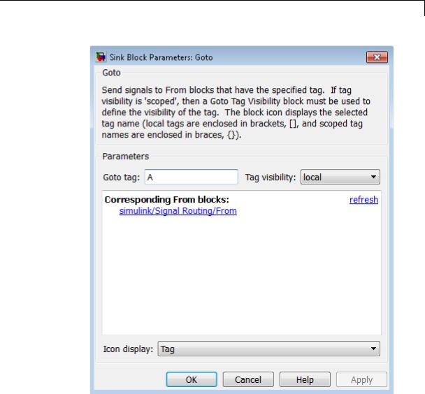
Goto
Parameters and Dialog Box
Goto Tag
The Goto block identifier. This parameter identifies the Goto block whose scope is defined in this block.
2-741

Goto
Tag Visibility
The scope of the Goto block tag: local, scoped, or global. The default is local.
Corresponding From blocks
|
|
List of the From blocks connected to this Goto block. |
||
|
|
Double-clicking any entry in this list displays and highlights the |
||
|
|
corresponding From block. |
|
|
|
|
Icon Display |
|
|
|
|
Specifies the text to display on the block’s icon. The options are |
||
|
|
the block’s tag, the name of the signal that the block represents, |
||
|
|
or both the tag and the signal name. |
||
Examples |
The following models show how to use the Goto block: |
|||
|
|
• sldemo_auto_climatecontrol |
||
|
|
• sldemo_hardstop |
|
|
Characteristics |
|
|
|
|
|
Sample Time |
|
Inherited from driving block |
|
|
|
Dimensionalized |
|
Yes |
|
|
Multidimensionalized |
|
Yes |
|
|
Virtual |
|
Yes |
|
|
|
|
For more information, see |
|
|
|
|
“Virtual Blocks” in the Simulink |
|
|
|
|
documentation. |
|
|
Zero-Crossing Detection |
|
No |
See Also |
|
From |
|
|
2-742
Goto Tag Visibility
Purpose |
Define scope of Goto block tag |
Library |
Signal Routing |
Description |
The Goto Tag Visibility block defines the accessibility of Goto block |
|
tags that have scoped visibility. The tag specified as the Goto tag |
|
parameter is accessible by From blocks in the same subsystem that |
|
contains the Goto Tag Visibility block and in subsystems below it in |
|
the model hierarchy. |
|
A Goto Tag Visibility block is required for Goto blocks whose Tag |
|
Visibility parameter value is scoped. No Goto Tag Visibility block is |
|
needed if the tag visibility is either local or global. The block shows |
|
the tag name enclosed in braces ({}). |
Data Type
Support
Not applicable.
2-743
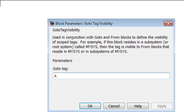
Goto Tag Visibility
Parameters and Dialog Box
Goto tag
The Goto block tag whose visibility is defined by the location of this block.
Characteristics |
Sample Time |
N/A |
|
Dimensionalized |
N/A |
|
Virtual |
Yes |
|
|
For more information, see |
|
|
“Virtual Blocks” in the Simulink |
|
|
documentation. |
2-744
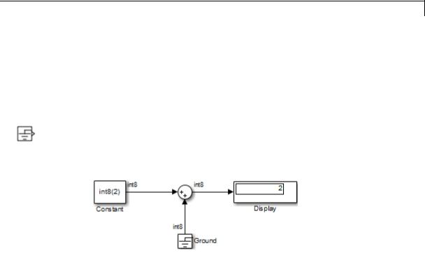
Ground
Purpose
Library
Description
Ground unconnected input port
Sources
The Ground block connects to blocks whose input ports do not connect to other blocks. If you run a simulation with blocks having unconnected input ports, Simulink issues warnings. Using a Ground block to ground those unconnected blocks can prevent these warnings.
The Ground block outputs a signal of the same data type as the port to which it connects. For example, consider the following model:
In this example, the output of the Constant block determines the data type (int8) of the port to which the Ground block is connected. That port determines the output data type of the Ground block.
The Ground block outputs a signal with zero value. When the output data type cannot represent zero exactly, the Ground block outputs a nonzero value that is the closest possible value to zero. This behavior applies only to fixed-point data types with nonzero bias. The following expressions are examples of fixed-point data types that cannot represent zero:
•fixdt(0, 8, 1, 1) — an unsigned 8-bit type with slope of 1 and bias of 1
• fixdt(1, 8, 6, 3) — a signed 8-bit type with slope of 6 and bias of 3
If the output is an enumerated data type, the Ground block outputs the default value of the enumeration. This behavior applies whether or not:
2-745
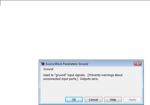
Ground
Data Type
Support
•The enumeration can represent zero.
•The default value of the enumeration is zero.
If the enumerated type does not have a default value, the Ground block outputs the first enumeration value in the type definition.
The Ground block supports all data types that Simulink supports, including fixed-point and enumerated data types. For more information, see “Data Types Supported by Simulink” in the Simulink documentation.
Parameters and Dialog Box
Examples |
The following Simulink examples show how to use the Ground block: |
|
|
• sldemo_doublebounce |
|
Characteristics |
|
|
Sample Time |
Constant (inf) |
|
|
Dimensionalized |
Yes |
|
|
|
2-746

Ground
Multidimensionalized |
Yes |
Virtual |
Yes |
|
For more information, see |
|
“Virtual Blocks” in the Simulink |
|
documentation. |
2-747

Hit Crossing
Purpose |
Detect crossing point |
Library Discontinuities
Description The Hit Crossing block detects when the input reaches the Hit crossing offset parameter value in the direction specified by the Hit crossing direction property.
The block accepts one input of type double. If you select the Show output port check box, the block output indicates when the crossing occurs. If the input signal is exactly the value of the offset value after the hit crossing is detected, the block continues to output a value of 1. If the input signals at two adjacent points bracket the offset value (but neither value is exactly equal to the offset), the block outputs a value of 1 at the second time step. If the Show output port check box is not selected, the block ensures that the simulation finds the crossing point but does not generate output. If the input signal is constant and equal to the offset value, the block outputs 1 only if the Hit crossing direction property is set to either.
When the block’s Hit crossing direction property is set to either, the block serves as an "Almost Equal" block, useful in working around limitations in finite mathematics and computer precision. Used for these reasons, this block might be more convenient than adding logic to your model to detect this condition.
When the block’s Hit crossing direction property is set to either and the model uses a fixed-step solver, the block has the following behavior. If the output signal is 1, the block sets the output signal to 0 at the next time step, unless the input signal equals the offset value.
Data Type The Hit Crossing block outputs a signal of type Boolean if Boolean logic
Support signals are enabled (see “Implement logic signals as Boolean data (vs. double)”). Otherwise, the block outputs a signal of type double.
2-748
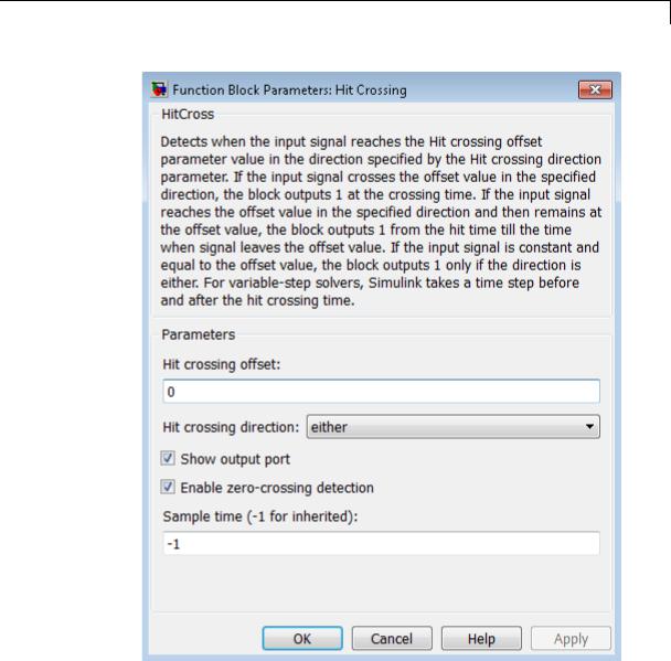
Hit Crossing
Parameters
2-749

Hit Crossing
and Dialog Box
Examples
Hit crossing offset
The value whose crossing is to be detected.
Hit crossing direction
The direction from which the input signal approaches the hit crossing offset for a crossing to be detected.
Show output port
If selected, draw an output port.
Enable zero-crossing detection
Select to enable zero-crossing detection. For more information, see “Zero-Crossing Detection” in the Simulink documentation.
Sample time (-1 for inherited)
Specify the time interval between samples. To inherit the sample time, set this parameter to -1. See “Specify Sample Time” in the online documentation for more information.
The sldemo_hardstop and sldemo_clutch models show how you can use the Hit Crossing block.
2-750
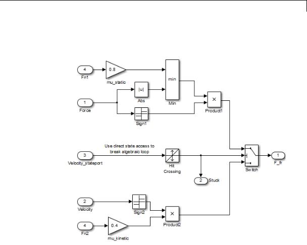
Hit Crossing
In the sldemo_hardstop model, the Hit Crossing block is in the Friction Model subsystem.
2-751
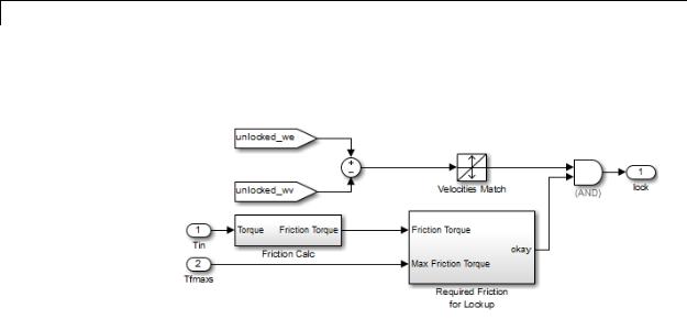
Hit Crossing
In the sldemo_clutch model, the Hit Crossing block is in the Friction Mode Logic/Lockup Detection subsystem.
Characteristics |
Direct Feedthrough |
Yes |
|
Sample Time |
Inherited from driving block |
|
Scalar Expansion |
Yes |
|
Dimensionalized |
Yes |
|
Zero-Crossing Detection |
Yes, if enabled. |
|
|
|
2-752
IC
Purpose
Library
Description
Data Type
Support
Set initial value of signal
Signal Attributes
The IC block sets the initial condition of the signal at its input port, for
example, the value of the signal at the simulation start time (tstart). The block does this by outputting the specified initial condition when you
start the simulation, regardless of the actual value of the input signal. Thereafter, the block outputs the actual value of the input signal.
Note If an IC block inherits or specifies a nonzero sample time offset (toffset), the IC block outputs its initial value at time t,
t = n * tperiod + toffset
where n is the smallest integer such that t tstart.
That is, the IC block outputs its initial value the first time blocks with sample time [tperiod, toffset] execute, which can be after tstart.
The IC block is useful for providing an initial guess for the algebraic state variables in a loop. For more information, see “Algebraic Loops”.
The IC block accepts and outputs signals of any Simulink built-in and fixed-point data type. The Initial value parameter accepts any built-in data type that Simulink supports. For more information, see “Data Types Supported by Simulink” in the Simulink documentation.
2-753
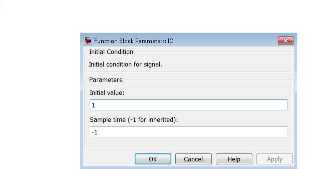
IC
Parameters and Dialog Box
Examples
Initial value
Specify the initial value for the input signal.
Sample time (-1 for inherited)
Specify the time interval between samples. To inherit the sample time, set this parameter to -1. See “Specify Sample Time” in the online documentation for more information.
The following examples show how to use the IC block:
•sldemo_bounce
•sldemo_hardstop
•sldemo_enginewc
2-754

IC
Characteristics |
Direct Feedthrough |
Yes |
|
Sample Time |
Specified in the Sample time |
|
|
parameter |
|
Scalar Expansion |
Yes, of Initial value parameter only |
|
Dimensionalized |
Yes |
|
Multidimensionalized |
Yes |
|
Zero-Crossing Detection |
No |
|
|
|
2-755
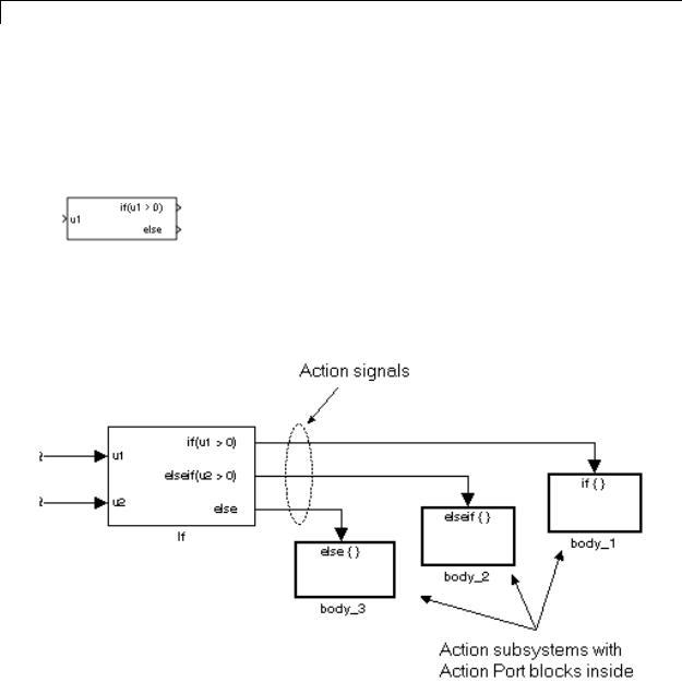
If
Purpose |
Model if-else control flow |
Library |
Ports & Subsystems |
Description |
|
The If block, along with If Action subsystems containing Action Port blocks, implements standard C-like if-else logic.
The following shows a completed if-else control flow statement.
2-756

If
In this example, the inputs to the If block determine the values of conditions represented as output ports. Each output port is attached to an If Action subsystem. The conditions are evaluated top down starting with the if condition. If a condition is true, its If Action subsystem is executed and the If block does not evaluate any remaining conditions.
The preceding if-else control flow statement can be represented by the following pseudocode.
if (u1 > 0) { body_1;
}
else if (u2 > 0){ body_2;
}
else { body_3;
}
You construct a Simulink if-else control flow statement like the preceding example as follows:
1Place an If block in the current system.
2Open the dialog of the If block and enter as follows:
•Enter the Number of inputs field with the required number of inputs necessary to define conditions for the if-else control flow statement.
Elements of vector inputs can be accessed for conditions using (row, column) arguments. For example, you can specify the fifth element of the vector u2 in the condition u2(5) > 0 in an If expression or Elseif expressions field.
•Enter the expression for the if condition of the if-else control flow statement in the If expression field.
2-757

If
This creates an if output port for the If block with a label of the form if(condition). This is the only required If Action signal output for an If block.
•Enter expressions for any elseif conditions of the if-else control flow statement in the Elseif expressions field.
Use a comma to separate one condition from another. Entering these conditions creates an output port for the If block for each condition, with a label of the form elseif(condition). elseif ports are optional and not required for operation of the If block.
•Check the Show else condition check box to create an else output port.
The else port is optional and not required for the operation of the If block.
3Create If Action subsystems to connect to each of the if, else, and elseif ports.
These consist of a subsystem with an Action Port block. When you place an Action Port block inside each subsystem, an input port named Action is added to the subsystem.
4Connect each if, else, and elseif port of the If block to the Action port of an If Action subsystem.
When you make the connection, the icon for the If Action block is renamed to the type of the condition that it attaches to.
Note During simulation of an if-else control flow statement, the Action signal lines from the If block to the If Action subsystems turn from solid to dashed.
5In each If Action subsystem, enter the Simulink blocks appropriate to the body to be executed for the condition it handles.
2-758
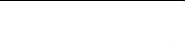
If
Data Type
Support
Note All blocks in an If Action Subsystem must run at the same rate as the driving If block. You can achieve this by setting each block’s sample time parameter to be either inherited (-1) or the same value as the If block’s sample time.
In the preceding example, the If Action subsystems are named body_1, body_2, and body_3.
Inputs u1,u2,...,un can be scalars or vectors of any built-in Simulink data type and must all be of the same data type. The inputs cannot be of any user-defined type, such as an enumerated type. Outputs from the if, else, and elseif ports are Action signals to If Action subsystems that you create by using Action Port blocks and subsystems.
For more information, see “Data Types Supported by Simulink” in the Simulink documentation.
2-759
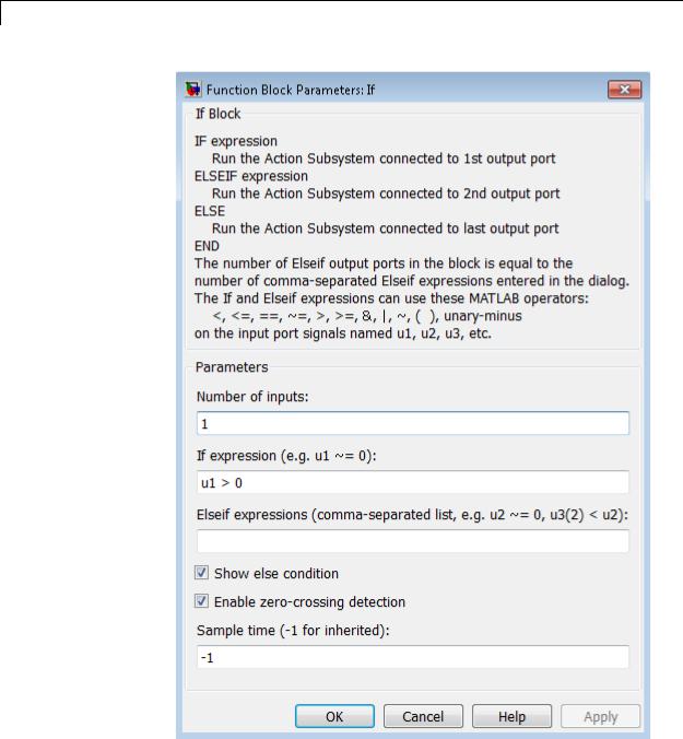
If
Parameters and Dialog Box
2-760
Number of inputs
Specify the number of inputs to the If block. These appear as data input ports labeled with a 'u' character followed by a number, 1,2,...,n, where n equals the number of inputs that you specify.

If
If expression
Specify the condition for the if output port. This condition appears on the If block adjacent to the if output port. The if expression can use any of the following operators: <. <=, ==, ~=, >, >=, &, |, ~, (), unary-minus. The If Action subsystem attached to the if port executes if its condition is
true. The expression must not contain data type expressions, for example, int8(6), and must not reference workspace variables whose data type is other than double or single.
Note You cannot tune this expression during simulation in Normal or Accelerator mode (see “How Acceleration Modes Work”), or in generated code.
The If block does not support custom storage classes. See “Custom Storage Classes” in the Embedded Coder documentation.
Elseif expressions
Specify a string list of elseif conditions delimited by commas. These conditions appear below the if port and above the else port when you select the Show else condition check box. elseif expressions can use any of the following operators: <, <=, ==, ~=, >, >=, &, |, ~, (), unary-minus. The If Action subsystem attached to an elseif port executes if its condition
is true and all of the if and elseif conditions are false. The expression must not contain data type expressions, for example, int8(6), and must not reference workspace variables whose data type is other than double or single.
Note You cannot tune these expressions during simulation in Normal or Accelerator mode (see “How Acceleration Modes Work”), or in generated code.
2-761
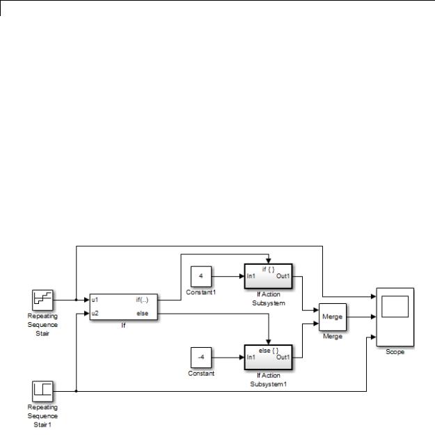
If
Show else condition
If you select this check box, an else port is created. The If Action subsystem attached to the else port executes if the if port and all the elseif ports are false.
Enable zero-crossing detection
Select to enable zero-crossing detection. For more information, see “Zero-Crossing Detection” in the Simulink documentation.
Sample time
Specify the sample time of the input signal. See “Specify Sample Time” in the online documentation for more information.
Examples The If block does not directly support fixed-point data types. However, you can use the Compare To Constant block to work around this limitation.
For example, consider the following floating-point model:
2-762
If
In this model, the If Action subsystems use their default configurations. The block and simulation parameters for the model are set to their default values except as follows:
|
Block or Dialog |
|
|
|
|
Box |
Parameter |
Setting |
|
|
Configuration |
Start time |
0.0 |
|
|
Parameters — |
|
|
|
|
Solver pane |
|
|
|
|
|
Stop time |
1.0 |
|
|
|
Type |
Fixed-step |
|
|
|
Solver |
discrete (no |
|
|
|
|
continuous states) |
|
|
|
Fixed-step size |
0.1 |
|
|
Repeating Sequence |
Vector of output |
[-2 -1 1 2].' |
|
|
Stair |
values |
|
|
|
Repeating Sequence |
Vector of output |
[0 0 0 0 1 1 1 |
|
|
Stair1 |
values |
1].' |
|
|
If |
Number of inputs |
2 |
|
|
|
If expression |
(u1 > 0) | (u2 > |
|
|
|
|
0.5) |
|
|
|
Show else |
selected |
|
|
|
condition |
|
|
|
Constant |
Constant value |
-4 |
|
|
Constant1 |
Constant value |
4 |
|
|
Scope |
Number of axes |
3 |
|
|
|
Time range |
1 |
|
|
|
|
|
|
2-763

If
For this model, if input u1 is greater than 0 or input u2 is greater than 0.5, the output is 4. Otherwise, the output is –4. The Scope block shows the output, u1, and u2:
2-764
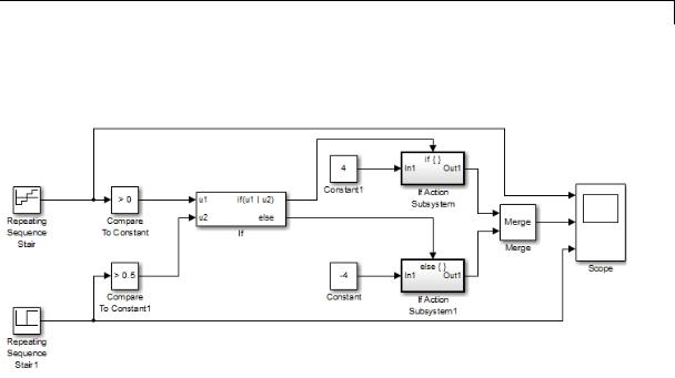
If
You can implement this block diagram as a model with fixed-point data types:
The Repeating Sequence Stair blocks now output fixed-point data types.
The Compare To Constant blocks implement two parts of the If expression that is used in the If block in the floating-point version of the model, (u1 > 0) and (u2 > 0.5). The OR operation, (u1|u2), can still be implemented inside the If block. For a fixed-point model, the expression must be partially implemented outside of the If block as it is here.
The block and simulation parameters for the fixed-point model are the same as for the floating-point model with the following exceptions and additions:
|
Block |
Parameter |
Setting |
|
|
Compare To |
Operator |
> |
|
|
Constant |
|
|
|
|
|
Constant value |
0 |
|
|
|
|
|
|
2-765

If
|
Block |
Parameter |
Setting |
|
||
|
|
Output data type |
Boolean |
|
||
|
|
mode |
|
|
|
|
|
|
Enable |
|
off |
|
|
|
|
zero-crossing |
|
|
||
|
|
detection |
|
|
|
|
|
Compare To |
Operator |
|
> |
|
|
|
Constant1 |
|
|
|
|
|
|
|
Constant value |
0.5 |
|
||
|
|
Output data type |
Boolean |
|
||
|
|
mode |
|
|
|
|
|
|
Enable |
|
off |
|
|
|
|
zero-crossing |
|
|
||
|
|
detection |
|
|
|
|
|
If |
Number of inputs |
2 |
|
||
|
|
If expression |
u1|u2 |
|
||
Characteristics |
|
|
|
|
|
|
Direct Feedthrough |
|
|
Yes |
|
|
|
|
Sample Time |
|
|
Inherited from driving block |
|
|
|
Scalar Expansion |
|
|
No |
|
|
|
Dimensionalized |
|
|
Yes |
|
|
|
Zero-Crossing Detection |
|
Yes, if enabled |
|
||
|
|
|
|
|
|
|
2-766

If Action Subsystem
Purpose |
Represent subsystem whose execution is triggered by If block |
Library |
Ports & Subsystems |
Description |
|
The If Action Subsystem block is a Subsystem block that is preconfigured to serve as a starting point for creating a subsystem whose execution is triggered by an If block.
Note All blocks in an If Action Subsystem must run at the same rate as the driving If block. You can achieve this by setting each block’s sample time parameter to be either inherited (-1) or the same value as the If block’s sample time.
For more information, see the If block and Modeling with Control Flow Blocks in the “Creating a Model” chapter of the Simulink documentation.
2-767
Increment Real World
Purpose |
Increase real world value of signal by one |
Library |
Additional Math & Discrete / Additional Math: Increment - Decrement |
Description |
The Increment Real World block increases the real world value of the |
|
signal by one. Overflows always wrap. |
Data Type |
The Increment Real World block accepts signals of the following data |
Support |
types: |
|
• Floating point |
|
• Built-in integer |
|
• Fixed point |
|
For more information, see “Data Types Supported by Simulink” in the |
|
Simulink documentation. |
Parameters and Dialog Box
Characteristics |
Direct Feedthrough |
Yes |
|
Scalar Expansion |
No |
|
|
|
2-768

Increment Real World
|
|
Multidimensionalized |
No |
|
|
Zero-Crossing Detection |
No |
See Also |
|
Decrement Real World, Increment Stored Integer |
|
2-769
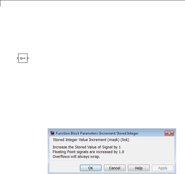
Increment Stored Integer
Purpose |
Increase stored integer value of signal by one |
Library |
Additional Math & Discrete / Additional Math: Increment - Decrement |
Description |
The Increment Stored Integer block increases the stored integer value |
|
of a signal by one. |
|
Floating-point signals also increase by one, and overflows always wrap. |
Data Type |
The Increment Stored Integer block accepts signals of the following |
Support |
data types: |
|
• Floating point |
|
• Built-in integer |
|
• Fixed point |
|
For more information, see “Data Types Supported by Simulink” in the |
|
Simulink documentation. |
Parameters and Dialog Box
2-770

Increment Stored Integer
Characteristics |
|
Direct Feedthrough |
Yes |
|
|
Scalar Expansion |
No |
|
|
Multidimensionalized |
No |
|
|
Zero-Crossing Detection |
No |
See Also |
|
Decrement Stored Integer, Increment Real World |
|
2-771

Index Vector
Purpose |
Switch output between different inputs based on value of first input |
Library |
Signal Routing |
Description |
The Index Vector block is an implementation of the Multiport Switch |
|
block. See Multiport Switch for more information. |
2-772
Inport
Purpose |
Create input port for subsystem or external input |
Library |
Ports & Subsystems, Sources |
Description |
Inport blocks are the links from outside a system into the system. |
|
Simulink software assigns Inport block port numbers according to |
|
these rules: |
|
• It automatically numbers the Inport blocks within a top-level system |
|
or subsystem sequentially, starting with 1. |
|
• If you add an Inport block, the label is the next available number. |
|
• If you delete an Inport block, other port numbers are automatically |
|
renumbered to ensure that the Inport blocks are in sequence and that |
|
no numbers are omitted. |
|
• If you copy an Inport block into a system, its port number is not |
|
renumbered unless its current number conflicts with an Inport block |
|
already in the system. If the copied Inport block port number is not in |
|
sequence, renumber the block. Otherwise, you get an error message |
|
when you run the simulation or update the block diagram. |
|
You can specify the dimensions of the input to the Inport block using |
|
the Port dimensions parameter. Entering a value of -1 lets Simulink |
|
determine the port dimension. |
|
The Sample time parameter is the rate at which the signal is coming |
|
into the system. A value of -1 causes the block to inherit its sample |
|
time from the block driving it. You might need to set this parameter for: |
|
• Inport blocks in a top-level system. |
|
• Models with blocks where Simulink cannot determine the sample |
|
time, but these blocks drive Inport blocks. |
|
For more information, see “Specify Sample Time”. |
2-773

Inport
Inport Blocks in a Top-Level System
Inport blocks in a top-level system have two uses:
•To supply external inputs from the workspace, use the Configuration Parameters dialog box (see “Techniques for Importing Signal Data”) or the ut argument of the sim command (see sim) to specify the inputs. If no external outputs are supplied, then the default output is the ground value.
•To provide a means for perturbation of the model by the linmod and trim analysis functions, use Inport blocks to inject inputs into the system.
Inport Blocks in a Subsystem
Inport blocks in a subsystem represent inputs to the subsystem. A signal arriving at an input port on a Subsystem block flows out of the associated Inport block in that subsystem. The Inport block associated with an input port on a Subsystem block is the block whose Port number parameter matches the relative position of the input port on the Subsystem block. For example, the Inport block whose Port number parameter is 1 gets its signal from the block connected to the topmost port on the Subsystem block.
If you renumber the Port number of an Inport block, the block becomes connected to a different input port, although the block continues to receive its signal from the same block outside the subsystem.
The Inport block name appears in the Subsystem icon as a port label. To suppress display of the label, select the Inport block and choose
Format > Hide Name.
Inport blocks inside a subsystem support signal label propagation, but root-level Inport blocks do not.
You can use a subsystem inport to supply fixed-point data in a structure or any other format.
2-774

Inport
Data Type
Support
Creating Duplicate Inports
You can create any number of duplicates of an Inport block. The duplicates are graphical representations of the original intended to simplify block diagrams by eliminating unnecessary lines. The duplicate has the same port number, properties, and output as the
original. Changing properties of a duplicate changes properties of the original and vice versa.
To create a duplicate of an Inport block:
1In the block diagram, select the block that you want to duplicate.
2In the Model Editor menu bar, select Edit > Copy.
3In the block diagram, place your cursor where you want to place the duplicate.
4Select Edit > Paste Duplicate Inport.
Connecting Buses to Root Level Inports
If you want a root level Inport of a model to produce a bus signal, you must set the Data type parameter to the name of a bus object that defines the bus that the Inport produces. For more information, see “Bus Objects”.
The Inport block accepts complex or real signals of any data type that Simulink supports, including fixed-point and enumerated data types. The Inport block also accepts a bus object as a data type.
2-775
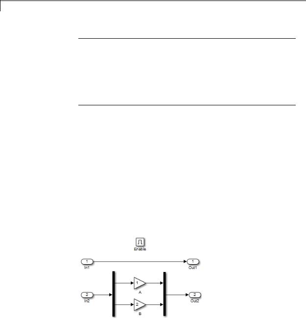
Inport
Note If you specify a bus object as the data type for this block, do not set the minimum and maximum values for bus data on the
block. Simulink ignores these settings. Instead, set the minimum and maximum values for bus elements of the bus object specified as the data type. The values should be finite real double scalar.
For information on the Minimum and Maximum properties of a bus element, see Simulink.BusElement.
For more information, see “Data Types Supported by Simulink”.
The numeric and data types of the block output are the same as those of its input. You can specify the signal type, data type, and sampling mode of an external input to a root-level Inport block using the Signal type,
Data type, and Sampling mode parameters.
The elements of a signal array connected to a root-level Inport block must be of the same numeric and data types. Signal elements connected to a subsystem input port can be of differing numeric and data types, except in the following circumstance: If the subsystem contains an Enable, Trigger, or Atomic Subsystem block and the input port, or an element of the input port, connects directly to an output port, the input elements must be of the same type. For example, consider the following enabled subsystem:
2-776

Inport
In this example, the elements of a signal vector connected to In1 must be of the same type. The elements connected to In2, however, can be of differing types.
2-777
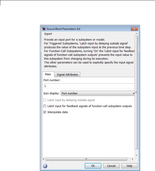
Inport
Parameters The Main pane of the Inport block dialog box appears as follows:
and Dialog Box
2-778

Inport
The Signal Attributes pane of the Inport block dialog box appears as follows:
2-779
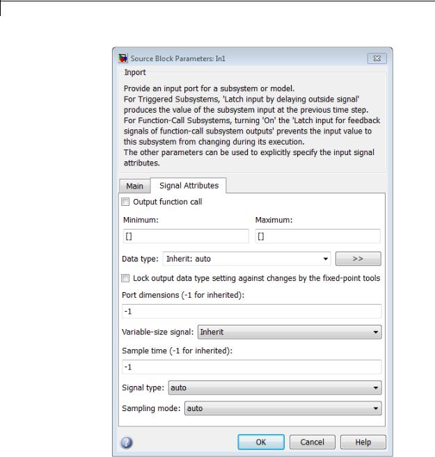
Inport
2-780

Inport
•“Package” on page 2-1941
•“Icon display” on page 2-1081
•“Latch input by delaying outside signal” on page 2-785
•“Latch input for feedback signals of function-call subsystem outputs” on page 2-786
•“Interpolate data” on page 2-788
•“Output function call” on page 2-789
•“Minimum” on page 2-1886
•“Maximum” on page 2-1887
•“Data type” on page 2-792
•“Show data type assistant” on page 2-1665
•“Mode” on page 2-795
•“Data type override” on page 2-1892
•“Signedness” on page 2-1893
•“Word length” on page 2-1896
•“Scaling” on page 2-1728
•“Fraction length” on page 2-1897
•“Slope” on page 2-1898
•“Bias” on page 2-1898
•“Output as nonvirtual bus” on page 2-803
•“Port dimensions (-1 for inherited)” on page 2-804
•“Variable-size signal” on page 2-805
•“Sample time (-1 for inherited)” on page 2-1938
•“Lock output data type setting against changes by the fixed-point tools” on page 2-1713
2-781

Inport
•“Signal type” on page 2-808
•“Sampling mode” on page 2-809
2-782
Inport
Port number
Specify the port number of the block.
Settings
Default: 1
This parameter controls the order in which the port that corresponds to the block appears on the parent subsystem or model block.
Command-Line Information
See “Block-Specific Parameters” on page 8-109 for the command-line information.
2-783

Inport
Icon display
Specify the information to be displayed on the icon of this input port.
Settings
Default: Port number
Signal name
Display the name of the signal connected to this port (or signals if the input is a bus).
Port number
Display port number of this port.
Port number and signal name
Display both the port number and the names of the signals connected to this port.
Command-Line Information
See “Block-Specific Parameters” on page 8-109 for the command-line information.
2-784
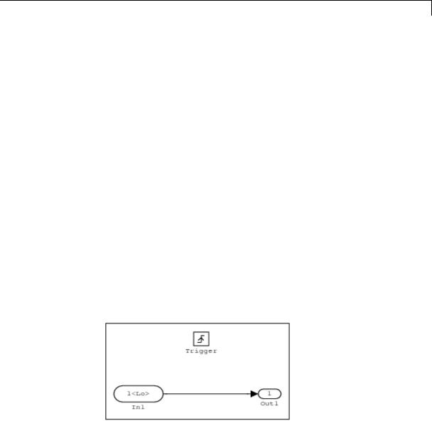
Inport
Latch input by delaying outside signal
Output the value of the input signal at the previous time step.
Settings
Default: Off
 On
On
Output the value of the input signal at the previous time step.
 Off
Off
Do not output the value of the input signal at the previous time step.
Tips
•This option applies only to triggered subsystems and is enabled only if the Inport block resides in a triggered subsystem.
•Selecting this check box enables Simulink to resolve data dependencies among triggered subsystems that are part of a loop.
•Type sl_subsys_semantics at the MATLAB prompt for examples using latched inputs with triggered subsystems.
•The Inport block indicates that this option is selected by displaying
<Lo>.
Command-Line Information
See “Block-Specific Parameters” on page 8-109 for the command-line information.
2-785

Inport
Latch input for feedback signals of function-call subsystem outputs
Latch the value of the input to this subsystem and prevent this value from changing during the execution of the subsystem. For a single function call that is branched to invoke multiple function-call
subsystems, this option allows you to break a loop formed by a signal fed back from one of these function-call subsystems into the other. A second functionality of this option is to prevent any change to the values of a feedback signal from a function-call subsystem that is invoked during the execution of this subsystem.
Settings
Default: Off
 On
On
Latch the input value.
 Off
Off
Do not latch the input value.
Tips
•This parameter applies only to function-call subsystems and is enabled only if the Inport block resides in a function-call subsystem.
•This parameter ensures that the subsystem inputs, including those generated within the subsystem’s context, do not change during execution of the subsystem.
•The Inport block indicates that this option is selected by displaying
<Li>.
2-786
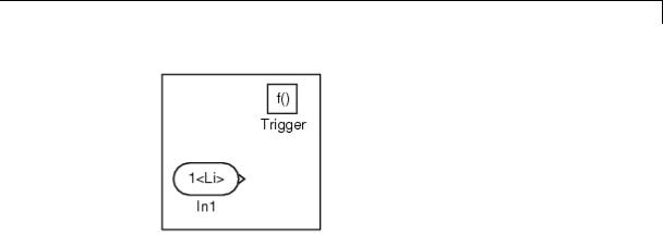
Inport
Command-Line Information
See “Block-Specific Parameters” on page 8-109 for the command-line information.
2-787

Inport
Interpolate data
Cause the block to interpolate or extrapolate output at time steps for which no corresponding workspace data exists when loading data from the workspace.
Settings
Default: On
 On
On
Cause the block to interpolate or extrapolate output at time steps for which no corresponding workspace data exists when loading data from the workspace.
 Off
Off
Do not cause the block to interpolate or extrapolate output at time steps for which no corresponding workspace data exists when loading data from the workspace.
Command-Line Information
See “Block-Specific Parameters” on page 8-109 for the command-line information.
2-788

Inport
Output function call
Specify that the input signal is outputting a function-call trigger signal.
Settings
Default: Off
 On
On
Input signal is the output of a function-call subsystem.
 Off
Off
Input signal is not the output of a function-call subsystem.
Tips
•Select this option if it is necessary for a current model to accept a function-call trigger signal when referenced in the top model.
•This feature is limited to an asynchronous function call.
Command-Line Information
See “Block-Specific Parameters” on page 8-109 for the command-line information.
2-789

Inport
Minimum
Specify the minimum value that the block should output.
Settings
Default: [] (unspecified)
This number must be a finite real double scalar value.
Note If you specify a bus object as the data type for this block, do not set the minimum value for bus data on the block. Simulink ignores this setting. Instead, set the minimum values for bus elements of the bus object specified as the data type. For information on the Minimum property of a bus element, see Simulink.BusElement.
Simulink software uses this value to perform:
•Simulation range checking (see “Signal Ranges”)
•Automatic scaling of fixed-point data types
Command-Line Information
See “Block-Specific Parameters” on page 8-109 for the command-line information.
2-790

Inport
Maximum
Specify the maximum value that the block should output.
Settings
Default: [] (unspecified)
This number must be a finite real double scalar value.
Note If you specify a bus object as the data type for this block, do not set the maximum value for bus data on the block. Simulink ignores this setting. Instead, set the maximum values for bus elements of the bus object specified as the data type. For information on the Maximum property of a bus element, see Simulink.BusElement.
Simulink software uses this value to perform:
•Simulation range checking (see “Signal Ranges”)
•Automatic scaling of fixed-point data types
Command-Line Information
See “Block-Specific Parameters” on page 8-109 for the command-line information.
2-791

Inport
Data type
Specify the output data type of the external input.
Settings
Default: Inherit: auto
Inherit: auto
A rule that inherits a data type
double
Data type is double.
single
Data type is single.
int8
Data type is int8.
uint8
Data type is uint8.
int16
Data type is int16.
uint16
Data type is uint16.
int32
Data type is int32.
uint32
Data type is uint32.
boolean
Data type is boolean.
fixdt(1,16,0)
Data type is fixed point fixdt(1,16,0).
fixdt(1,16,2^0,0)
Data type is fixed point fixdt(1,16,2^0,0).
2-792
Inport
Enum: <class name>
Data type is enumerated, for example, Enum: Basic Colors.
Bus: <object name>
Data type is a bus object.
<data type expression>
The name of a data type object, for example
Simulink.NumericType
Do not specify a bus object as the expression.
Command-Line Information
See “Block-Specific Parameters” on page 8-109 for the command-line information.
2-793

Inport
Show data type assistant
Display the Data Type Assistant.
Settings
The Data Type Assistant helps you set the Output data type parameter.
For more information, see “Specify Block Output Data Types”.
Command-Line Information
See “Block-Specific Parameters” on page 8-109 for the command-line information.
2-794

Inport
Mode
Select the category of data to specify.
Settings
Default: Inherit
Inherit
Inheritance rule for data types. Selecting Inherit enables a second menu/text box to the right.
Built in
Built-in data types. Selecting Built in enables a second menu/text box to the right. Select one of the following choices:
•double (default)
•single
•int8
•uint8
•int16
•uint16
•int32
•uint32
•boolean
Fixed point
Fixed-point data types.
Enumerated
Enumerated data types. Selecting Enumerated enables a second menu/text box to the right, where you can enter the class name.
Bus
Bus object. Selecting Bus enables a Bus object parameter to the right, where you enter the name of a bus object that you want to use to define the structure of the bus. If you need to create or
2-795

Inport
change a bus object, click Edit to the right of the Bus object field to open the Simulink Bus Editor. For details about the Bus Editor, see “Manage Bus Objects with the Bus Editor”.
Expression
Expressions that evaluate to data types. Selecting Expression enables a second menu/text box to the right, where you can enter the expression.
Do not specify a bus object as the expression.
Dependency
Clicking the Show data type assistant button enables this parameter.
Command-Line Information
See “Block-Specific Parameters” on page 8-109 for the command-line information.
See Also
See “Specify Data Types Using Data Type Assistant”.
2-796

Inport
Data type override
Specify data type override mode for this signal.
Settings
Default: Inherit
Inherit
Inherits the data type override setting from its context, that is, from the block, Simulink.Signal object or Stateflow chart in Simulink that is using the signal.
Off
Ignores the data type override setting of its context and uses the fixed-point data type specified for the signal.
Tip
The ability to turn off data type override for an individual data type provides greater control over the data types in your model when you apply data type override. For example, you can use this option to ensure that data types meet the requirements of downstream blocks regardless of the data type override setting.
Dependency
This parameter appears only when the Mode is Built in or Fixed point.
2-797

Inport
Signedness
Specify whether you want the fixed-point data as signed or unsigned.
Settings
Default: Signed
Signed
Specify the fixed-point data as signed.
Unsigned
Specify the fixed-point data as unsigned.
Dependencies
Selecting Mode > Fixed point enables this parameter.
Command-Line Information
See “Block-Specific Parameters” on page 8-109 for the command-line information.
See Also
For more information, see “Specifying a Fixed-Point Data Type”.
2-798

Inport
Word length
Specify the bit size of the word that holds the quantized integer.
Settings
Default: 16
Minimum: 0
Maximum: 32
Dependencies
Selecting Mode > Fixed point enables this parameter.
Command-Line Information
See “Block-Specific Parameters” on page 8-109 for the command-line information.
See Also
For more information, see “Specifying a Fixed-Point Data Type”.
2-799

Inport
Scaling
Specify the method for scaling your fixed-point data to avoid overflow conditions and minimize quantization errors.
Settings
Default: Best precision
Binary point
Specify binary point location.
Slope and bias
Enter slope and bias.
Best precision
Specify best-precision values.
Dependencies
Selecting Mode > Fixed point enables this parameter. Selecting Binary point enables:
•Fraction length
•Calculate Best-Precision Scaling
Selecting Slope and bias enables:
•Slope
•Bias
•Calculate Best-Precision Scaling
Command-Line Information
See “Block-Specific Parameters” on page 8-109 for the command-line information.
See Also
For more information, see “Specifying a Fixed-Point Data Type”.
2-800

Inport
Fraction length
Specify fraction length for fixed-point data type.
Settings
Default: 0
Binary points can be positive or negative integers.
Dependencies
Selecting Scaling > Binary point enables this parameter.
Command-Line Information
See “Block-Specific Parameters” on page 8-109 for the command-line information.
See Also
For more information, see “Specifying a Fixed-Point Data Type”.
2-801

Inport
Slope
Specify slope for the fixed-point data type.
Settings
Default: 2^0
Specify any positive real number.
Dependencies
Selecting Scaling > Slope and bias enables this parameter.
Command-Line Information
See “Block-Specific Parameters” on page 8-109 for the command-line information.
See Also
For more information, see “Specifying a Fixed-Point Data Type”.
Bias
Specify bias for the fixed-point data type.
Settings
Default: 0
Specify any real number.
Dependencies
Selecting Scaling > Slope and bias enables this parameter.
Command-Line Information
See “Block-Specific Parameters” on page 8-109 for the command-line information.
See Also
For more information, see “Specifying a Fixed-Point Data Type”.
2-802
Inport
Output as nonvirtual bus
Output a nonvirtual bus.
Settings
Default: Off
 On
On
Output a nonvirtual bus.
 Off
Off
Output a virtual bus.
Tips
•Select this option if you want code generated from this model to use a C structure to define the structure of the bus signal output by this block.
•All signals in a nonvirtual bus must have the same sample time, even if the elements of the associated bus object specify inherited sample times. Any bus operation that would result in a nonvirtual bus that violates this requirement generates an error. Therefore, if you select this option all signals in the bus must have the same sample time. You can use a Rate Transition block to change the sample time of an individual signal, or of all signals in a bus, to allow the signal or bus to be included in a nonvirtual bus.
Dependency
Specify properties via bus object enables this parameter.
Command-Line Information
See “Block-Specific Parameters” on page 8-109 for the command-line information.
2-803

Inport
Port dimensions (-1 for inherited)
Specify the dimensions of the input signal to the block.
Settings
Default: -1
Valid values are:
-1 |
Dimensions are inherited from input signal |
n |
Vector signal of width n accepted |
[m n] |
Matrix signal having m rows and n columns accepted |
|
|
Dependency
Clearing Specify properties via bus object enables this parameter.
Command-Line Information
See “Block-Specific Parameters” on page 8-109 for the command-line information.
2-804