

- •Block Reference
- •Commonly Used
- •Continuous
- •Discontinuities
- •Discrete
- •Logic and Bit Operations
- •Lookup Tables
- •Math Operations
- •Model Verification
- •Model-Wide Utilities
- •Ports & Subsystems
- •Signal Attributes
- •Signal Routing
- •Sinks
- •Sources
- •User-Defined Functions
- •Additional Math & Discrete
- •Additional Discrete
- •Additional Math: Increment — Decrement
- •Run on Target Hardware
- •Target for Use with Arduino Hardware
- •Target for Use with BeagleBoard Hardware
- •Target for Use with LEGO MINDSTORMS NXT Hardware
- •Blocks — Alphabetical List
- •Command-Line Information
- •Command-Line Information
- •Command-Line Information
- •Command-Line Information
- •Command-Line Information
- •Command-Line Information
- •Command-Line Information
- •Command-Line Information
- •Command-Line Information
- •Command-Line Information
- •Command-Line Information
- •Command-Line Information
- •Command-Line Information
- •Command-Line Information
- •Command-Line Information
- •Command-Line Information
- •Settings Pane
- •Measurements Pane
- •Signal Statistics Measurements
- •Settings Pane
- •Transitions Pane
- •Overshoots/Undershoots
- •Cycles
- •Settings Pane
- •Peaks Pane
- •Command-Line Information
- •Command-Line Information
- •Command-Line Information
- •Command-Line Information
- •Command-Line Information
- •Command-Line Information
- •Command-Line Information
- •Command-Line Information
- •Command-Line Information
- •Function Reference
- •Model Construction
- •Simulation
- •Linearization and Trimming
- •Data Type
- •Examples
- •Main Toolbar
- •Command-Line Alternative
- •Command-Line Alternative
- •Command-Line Alternative
- •Command-Line Alternative
- •Command-Line Alternative
- •Command-Line Alternative
- •Mask Icon Drawing Commands
- •Simulink Classes
- •Model Parameters
- •About Model Parameters
- •Examples of Setting Model Parameters
- •Common Block Parameters
- •About Common Block Parameters
- •Examples of Setting Block Parameters
- •Block-Specific Parameters
- •Mask Parameters
- •About Mask Parameters
- •Notes on Mask Parameter Storage
- •Simulink Identifier
- •Simulink Identifier
- •Model Advisor Checks
- •Simulink Checks
- •Simulink Check Overview
- •See Also
- •Identify unconnected lines, input ports, and output ports
- •Description
- •Results and Recommended Actions
- •Capabilities and Limitations
- •Tips
- •See Also
- •Check root model Inport block specifications
- •Description
- •Results and Recommended Actions
- •See Also
- •Check optimization settings
- •Description
- •Results and Recommended Actions
- •Tips
- •See Also
- •Description
- •Results and Recommended Actions
- •See Also
- •Check for implicit signal resolution
- •Description
- •Results and Recommended Actions
- •See Also
- •Check for optimal bus virtuality
- •Description
- •Results and Recommended Actions
- •Capabilities and Limitations
- •See Also
- •Description
- •Results and Recommended Actions
- •Capabilities and Limitations
- •See Also
- •Identify disabled library links
- •Description
- •Results and Recommended Actions
- •Capabilities and Limitations
- •Tips
- •See Also
- •Identify parameterized library links
- •Description
- •Results and Recommended Actions
- •Capabilities and Limitations
- •Tips
- •See Also
- •Identify unresolved library links
- •Description
- •Results and Recommended Actions
- •Capabilities and Limitations
- •See Also
- •Results and Recommended Actions
- •Capabilities and Limitations
- •See Also
- •Results and Recommended Actions
- •Capabilities and Limitations
- •See Also
- •Check usage of function-call connections
- •Description
- •Results and Recommended Actions
- •See Also
- •Check signal logging save format
- •Description
- •Results and Recommended Actions
- •See Also
- •Description
- •Results and Recommended Actions
- •See Also
- •Description
- •Results and Recommended Actions
- •Tips
- •See Also
- •Check data store block sample times for modeling errors
- •Description
- •Results and Recommended Actions
- •See Also
- •Check for potential ordering issues involving data store access
- •Description
- •Results and Recommended Actions
- •Tips
- •See Also
- •Check for partial structure parameter usage with bus signals
- •Description
- •Results and Recommended Actions
- •Tips
- •See Also
- •Check for calls to slDataTypeAndScale
- •Description
- •Results and Recommended Actions
- •Tips
- •See Also
- •Check for proper bus usage
- •Description
- •Results and Recommended Actions
- •Action Results
- •Tips
- •See Also
- •Description
- •Results and Recommended Actions
- •See Also
- •Description
- •Results and Recommended Actions
- •See Also
- •Check for proper Merge block usage
- •Description
- •Input Parameters
- •Results and Recommended Actions
- •See Also
- •Description
- •Results and Recommended Actions
- •Action Results
- •See Also
- •Check for non-continuous signals driving derivative ports
- •Description
- •Results and Recommended Actions
- •See Also
- •Runtime diagnostics for S-functions
- •Description
- •Results and Recommended Actions
- •See Also
- •Check file for foreign characters
- •Description
- •Results and Recommended Actions
- •Tips
- •See Also
- •Check model for known block upgrade issues
- •Description
- •Results and Recommended Actions
- •Action Results
- •See Also
- •Description
- •Results and Recommended Actions
- •Action Results
- •See Also
- •Check that the model is saved in SLX format
- •Description
- •Results and Recommended Actions
- •Tips
- •See Also
- •Check Model History properties
- •Description
- •Results and Recommended Actions
- •See Also
- •Analyze model hierarchy for upgrade issues
- •Description
- •Results and Recommended Actions
- •Tips
- •See Also
- •Description
- •Results and Recommended Actions
- •See Also
- •Simulink Performance Advisor Checks
- •Simulink Performance Advisor Check Overview
- •See Also
- •Baseline
- •See Also
- •Check Preupdate Items
- •See Also
- •Checks that need Update Diagram
- •See Also
- •Checks that require simulation to run
- •See Also
- •Check Accelerator Settings
- •See Also
- •Create Baseline
- •See Also
- •Identify resource intensive diagnostic settings
- •See Also
- •Check optimization settings
- •See Also
- •Identify inefficient lookup table blocks
- •See Also
- •Identify Interpreted MATLAB Function blocks
- •See Also
- •Check MATLAB Function block debug settings
- •See Also
- •Check Stateflow block debug settings
- •See Also
- •Identify simulation target settings
- •See Also
- •Check model reference rebuild setting
- •See Also
- •Check Model Reference parallel build
- •See Also
- •Check solver type selection
- •See Also
- •Select normal or accelerator simulation mode
- •See Also
- •Simulink Limits
- •Maximum Size Limits of Simulink Models
- •Index
- •Filter Structures and Filter Coefficients
- •Valid Initial States
- •Number of Delay Elements (Filter States)
- •Frame-Based Processing
- •Sample-Based Processing
- •Valid Initial States
- •Frame-Based Processing
- •Sample-Based Processing
- •Model Parameters in Alphabetical Order
- •Common Block Parameters
- •Continuous Library Block Parameters
- •Discontinuities Library Block Parameters
- •Discrete Library Block Parameters
- •Logic and Bit Operations Library Block Parameters
- •Lookup Tables Block Parameters
- •Math Operations Library Block Parameters
- •Model Verification Library Block Parameters
- •Model-Wide Utilities Library Block Parameters
- •Ports & Subsystems Library Block Parameters
- •Signal Attributes Library Block Parameters
- •Signal Routing Library Block Parameters
- •Sinks Library Block Parameters
- •Sources Library Block Parameters
- •User-Defined Functions Library Block Parameters
- •Additional Discrete Block Library Parameters
- •Additional Math: Increment - Decrement Block Parameters
- •Mask Parameters
Manual Switch
Allow the two inputs to differ in size
Select this check box to allow input signals with different sizes.
Settings
Default: Off
 On
On
Allows input signals with different sizes, and propagate the input signal size to the output signal.
 Off
Off
Requires that all input signals be the same size.
Command-Line Information
Parameter: varsize
Type: string
Value: 'on' | 'off'
Default: 'off'
Sample time (-1 for inherited)
Enter the discrete interval between sample time hits or specify another appropriate sample time such as continuous or inherited.
Settings
Default: -1
Examples
By default, the block inherits its sample time based upon the context of the block within the model. To set a different sample time, enter a valid sample time based upon the table in “Types of Sample Time”.
See also “Specify Sample Time” in the online documentation for more information.
Command-Line Information
See “Block-Specific Parameters” on page 8-109 for the command-line information.
The following models show how to use the Manual Switch block:
• sldemo_auto_climatecontrol
2-923

Manual Switch
• sldemo_fuelsys
• sldemo_doublebounce
Characteristics |
Direct Feedthrough |
Yes |
|
Sample Time |
Specified in the Sample time |
|
|
parameter |
|
Scalar Expansion |
Yes |
|
Dimensionalized |
Yes |
|
Multidimensionalized |
Yes |
|
Zero-Crossing Detection |
No |
|
|
|
2-924

Math Function
Purpose |
Perform mathematical function |
Library |
Math Operations |
Description |
The Math Function block performs numerous common mathematical |
|
functions. |
|
|
|
Tip To perform square root calculations, use the Sqrt block. |
|
|
You can select one of the following functions from the Function parameter list.
|
Function |
Description |
Mathematical |
MATLAB |
|
|
|
|
Expression |
Equivalent |
|
|
exp |
Exponential |
eu |
exp |
|
|
log |
Natural logarithm |
ln u |
log |
|
|
10^u |
Power of base 10 |
10u |
10.^u |
|
|
|
|
|
(see power) |
|
|
log10 |
Common (base 10) |
log u |
log10 |
|
|
|
logarithm |
|
|
|
|
magnitude^2 |
Complex modulus |
|u|2 |
(abs(u)).^2 |
|
|
|
|
|
(see abs and power) |
|
|
square |
Power 2 |
u2 |
u.^2 |
|
|
|
|
|
(see power) |
|
|
pow |
Power |
uv |
power |
|
|
conj |
Complex conjugate |
|
conj |
|
|
reciprocal |
Reciprocal |
1/u |
1./u |
|
|
|
|
|
(see rdivide) |
|
|
hypot |
Square root of sum |
(u2+v2)0.5 |
hypot |
|
|
|
squares |
|
|
|
2-925

Math Function
|
Function |
|
Description |
Mathematical |
MATLAB |
|
|
|
|
|
Expression |
Equivalent |
|
|
rem |
|
Remainder after |
— |
rem |
|
|
|
|
division |
|
|
|
|
mod |
|
Modulus after |
— |
mod |
|
|
|
|
division |
|
|
|
|
transpose |
|
Transpose |
uT |
u.' |
|
|
|
|
|
|
(see arithmetic |
|
|
|
|
|
|
operators) |
|
|
hermitian |
|
Complex conjugate |
uH |
u' |
|
|
|
|
transpose |
|
(see arithmetic |
|
|
|
|
|
|
operators) |
|
|
|
The block output is the result of the operation of the function on the |
||||
|
|
input or inputs. The functions support the following types of operations. |
||||
|
Function |
Scalar Operations |
Element-Wise |
Vector and Matrix |
|
|
|
|
Vector and Matrix |
Operations |
|
|
|
|
Operations |
|
|
|
exp |
yes |
yes |
— |
|
|
log |
yes |
yes |
— |
|
|
10^u |
yes |
yes |
— |
|
|
log10 |
yes |
yes |
— |
|
|
magnitude^2 |
yes |
yes |
— |
|
|
square |
yes |
yes |
— |
|
|
pow |
yes |
yes |
— |
|
|
conj |
yes |
yes |
— |
|
|
reciprocal |
yes |
yes |
— |
|
|
|
|
|
|
|
2-926

Math Function
|
Function |
Scalar Operations |
Element-Wise |
Vector and Matrix |
|
|
|
|
Vector and Matrix |
Operations |
|
|
|
|
Operations |
|
|
|
hypot |
yes, on two inputs |
yes, on two inputs |
— |
|
|
|
|
(two vectors or two |
|
|
|
|
|
matrices of the same |
|
|
|
|
|
size, a scalar and a |
|
|
|
|
|
vector, or a scalar |
|
|
|
|
|
and a matrix) |
|
|
|
rem |
yes, on two inputs |
yes, on two inputs |
— |
|
|
|
|
(two vectors or two |
|
|
|
|
|
matrices of the same |
|
|
|
|
|
size, a scalar and a |
|
|
|
|
|
vector, or a scalar |
|
|
|
|
|
and a matrix) |
|
|
|
mod |
yes, on two inputs |
yes, on two inputs |
— |
|
|
|
|
(two vectors or two |
|
|
|
|
|
matrices of the same |
|
|
|
|
|
size, a scalar and a |
|
|
|
|
|
vector, or a scalar |
|
|
|
|
|
and a matrix) |
|
|
|
transpose |
yes |
— |
yes |
|
|
hermitian |
yes |
— |
yes |
|
|
|
|
|
|
|
The name of the function appears on the block. The appropriate number of input ports appears automatically.
Tip Use the Math Function block instead of the Fcn block when you want vector or matrix output, because the Fcn block produces only scalar output.
2-927

Math Function
Data Type
Support
The following table shows the input data types that each function of the block can support.
|
Function |
single |
double |
boolean |
built-in |
fixed |
|
|
|
|
|
|
integer |
point |
|
|
exp |
yes |
yes |
— |
— |
— |
|
|
log |
yes |
yes |
— |
— |
— |
|
|
10^u |
yes |
yes |
— |
— |
— |
|
|
log10 |
yes |
yes |
— |
— |
— |
|
|
magnitude^2 |
yes |
yes |
— |
yes |
yes |
|
|
square |
yes |
yes |
— |
yes |
yes |
|
|
pow |
yes |
yes |
— |
— |
— |
|
|
conj |
yes |
yes |
— |
yes |
yes |
|
|
reciprocal |
yes |
yes |
— |
yes |
yes |
|
|
hypot |
yes |
yes |
— |
— |
— |
|
|
rem |
yes |
yes |
— |
yes |
— |
|
|
mod |
yes |
yes |
— |
yes |
— |
|
|
transpose |
yes |
yes |
yes |
yes |
yes |
|
|
hermitian |
yes |
yes |
— |
yes |
yes |
|
|
|
|
|
|
|
|
|
All supported modes accept both real and complex inputs, except for reciprocal, which does not accept complex fixed-point inputs.
The block output is real or complex, depending on what you select for
Output signal type.
2-928
Math Function
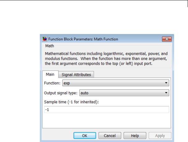
Parameters |
The Main pane of the Math Function block dialog box appears as |
and |
follows: |
Dialog |
|
Box |
|
Function
Specify the mathematical function. See Description for more information about the options for this parameter.
Output signal type
Specify the output signal type of the Math Function block as auto, real, or complex.
2-929

Math Function
|
Function |
Input Signal |
|
Output Signal Type |
|
||
|
|
Type |
|
|
|
|
|
|
|
Auto |
|
Real |
Complex |
|
|
|
|
|
|
|
|||
|
exp, log, 10u, |
real |
real |
|
real |
complex |
|
|
log10, square, |
complex |
complex |
|
error |
complex |
|
|
pow, reciprocal, |
|
|
||||
|
conjugate, |
|
|
|
|
|
|
|
transpose, |
|
|
|
|
|
|
|
hermitian |
|
|
|
|
|
|
|
|
|
|
|
|
|
|
|
magnitude |
real |
real |
|
real |
complex |
|
|
squared |
complex |
real |
|
real |
complex |
|
|
|
|
|
||||
|
hypot, rem, mod |
real |
real |
|
real |
complex |
|
|
|
complex |
error |
|
error |
error |
|
|
|
|
|
|
|
|
|
Sample time (-1 for inherited)
Specify the time interval between samples. To inherit the sample time, set this parameter to -1. See “Specify Sample Time” in the online documentation for more information.
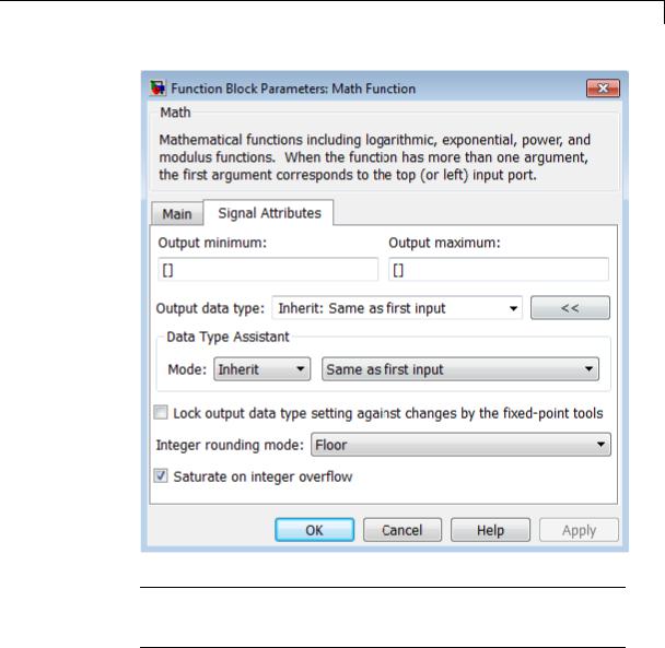
The Signal Attributes pane of the Math Function block dialog box appears as follows:
2-930
Math Function
Note Some parameters on this pane are available only when the function you select in the Function parameter supports fixed-point data types.
2-931

Math Function
Output minimum
Specify the minimum value that the block can output. The default value is [] (unspecified). Simulink software uses this value to perform:
•Simulation range checking (see “Signal Ranges”)
•Automatic scaling of fixed-point data types
Output maximum
Specify the maximum value that the block can output. The default value is [] (unspecified). Simulink software uses this value to perform:
•Simulation range checking (see “Signal Ranges”)
•Automatic scaling of fixed-point data types
Output data type
Specify the output data type. You can set it to:
•A rule that inherits a data type, for example, Inherit: Inherit via back propagation
•The name of a built-in data type, for example, single
•The name of a data type object, for example, a
Simulink.NumericType object
•An expression that evaluates to a data type, for example, fixdt(1,16,0)
Click the Show data type assistant button  to display the Data Type Assistant, which helps you set the
Output data type parameter.
See “Specify Block Output Data Types” in Simulink User’s Guide for more information.
2-932
Math Function
Lock output data type setting against changes by the fixed-point tools
Select to lock the output data type setting of this block against changes by the Fixed-Point Tool and the Fixed-Point Advisor. For more information, see “Use Lock Output Data Type Setting”.
Integer rounding mode
Specify the rounding mode for fixed-point operations. For more information, see “Rounding”. in the Simulink Fixed Point documentation.
Saturate on integer overflow
|
Action |
Reasons for Taking |
What Happens for |
Example |
|
|
This Action |
Overflows |
|
|
Select this |
Your model has |
Overflows saturate to |
An overflow associated |
|
check box. |
possible overflow, |
either the minimum |
with a signed 8-bit |
|
|
and you want explicit |
or maximum value |
integer can saturate to |
|
|
saturation protection |
that the data type can |
–128 or 127. |
|
|
in the generated code. |
represent. |
|
|
Do not select |
You want to optimize |
Overflows wrap to the |
The number 130 does |
|
this check |
efficiency of your |
appropriate value that |
not fit in a signed 8-bit |
|
box. |
generated code. |
is representable by the |
integer and wraps to |
|
|
You want to avoid |
data type. |
–126. |
|
|
|
|
|
|
|
overspecifying how |
|
|
|
|
a block handles |
|
|
|
|
out-of-range signals. |
|
|
|
|
For more information, |
|
|
|
|
see “Checking for |
|
|
|
|
Signal Range Errors”. |
|
|
|
|
When you select this check box, saturation applies to every |
||
|
|
internal operation on the block, not just the output or result. |
||
|
|
Usually, the code generation process can detect when overflow is |
||
|
|
not possible. In this case, the code generator does not produce |
||
|
|
saturation code. |
|
|
2-933

Math Function
Characteristics |
|
Direct Feedthrough |
Yes |
|
|
Sample Time |
Specified in the Sample time |
|
|
|
parameter |
|
|
Scalar Expansion |
Yes, of the input when the function |
|
|
|
requires two inputs |
|
|
Dimensionalized |
Yes |
|
|
Multidimensionalized |
Yes, for all functions except |
|
|
|
hermitian and transpose |
|
|
Zero-Crossing Detection |
No |
See Also |
|
Sqrt, Trigonometric Function |
|
2-934
MATLAB Function
Purpose
Library
Description
Include MATLAB code in models that generate embeddable C code
User-Defined Functions
With a MATLAB Function block, you can write a MATLAB function for use in a Simulink model. The MATLAB function you create executes for simulation and generates code for a Simulink Coder target. If you are new to the Simulink and MATLAB products, see “What Is a MATLAB Function Block?” and “Create Model That Uses MATLAB Function Block” for an overview.
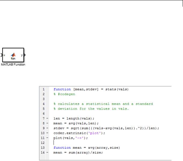
Double-clicking the MATLAB Function block opens its editor, where you write the MATLAB function, as in this example:
To learn more about this editor, see “MATLAB Function Block Editor”.
You specify input and output data to the MATLAB Function block in the function header as arguments and return values. The argument and return values of the preceding example function correspond to the inputs and outputs of the block in the model:
2-935
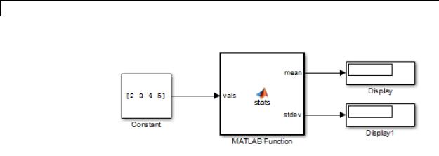
MATLAB Function
You can also define data, input triggers, and function call outputs using the Ports and Data Manager, which you access from the MATLAB Function Block Editor by selecting Edit Data. See “Ports and Data Manager”.
The MATLAB Function block generates efficient embeddable code based on an analysis that determines the size, class, and complexity of each variable. This analysis imposes the following restrictions:
•The first assignment to a variable defines its, size, class, and complexity.
See “Best Practices for Defining Variables for C/C++ Code Generation”.
•You cannot reassign variable properties after the initial assignment except when using variable-size data or reusing variables in the code for different purposes.
See “Reassignment of Variable Properties”.
In addition to language restrictions, the MATLAB Function block supports a subset of the functions available in MATLAB. A list of supported functions is given in “Functions Supported for Code
Generation — Alphabetical List”. These functions include functions in common categories, such as:
• Arithmetic Operators like plus, minus, and power
2-936

MATLAB Function
Data Type
Support
•Matrix operations like size, and length
•Advanced matrix operations like lu, inv, svd, and chol
•Trigonometric functions like sin, cos, sinh, and cosh
See “Functions Supported for Code Generation — Categorical List” for a complete list of function categories.
Note Although the code for this block attempts to produce exactly the same results as MATLAB, differences might occur due to rounding errors. These numerical differences, which might be a few eps initially, can magnify after repeated operations. Reliance on the behavior of nan is not recommended. Different C compilers can yield different results for the same computation.
To support visualization of data, the MATLAB Function block supports calls to MATLAB functions for simulation only. See “Call MATLAB Functions” to understand some of the limitations of this capability, and how it integrates with code analysis for this block. If these function calls do not directly affect any of the Simulink inputs or outputs, the calls do not appear in Simulink Coder generated code.
In the Ports and Data Manager, you can declare a block input to be a Simulink parameter instead of a port. The MATLAB Function block also supports inheritance of types and size for inputs, outputs, and parameters. You can also specify these properties explicitly. See “Type Function Arguments”, “Size Function Arguments”, and “Add Parameter Arguments” for descriptions of variables that you use in MATLAB Function blocks.
Recursive calls are not allowed in MATLAB Function blocks.
The MATLAB Function block accepts inputs of any type that Simulink supports, including fixed-point and enumerated types. For more information, see “Data Types Supported by Simulink”.
2-937

MATLAB Function
Parameters and Dialog Box
Examples
For more information on fixed-point support for this block, refer to “Fixed-Point Data Types with MATLAB Function Block”.
The MATLAB Function block supports Simulink frames. For more information, see “Sampleand Frame-Based Concepts”.
The block dialog box for a MATLAB Function block is identical to the dialog box for a Subsystem block. See the reference page for the Subsystem, Atomic Subsystem, Nonvirtual Subsystem, CodeReuse Subsystem blocks for information about each block parameter.
The following models shows how to use the MATLAB Function block:
•sldemo_radar_eml
•sldemo_eml_galaxy
Characteristics |
Direct Feedthrough |
Yes |
|
Sample Time |
Specified in the Sample time |
|
|
parameter |
|
Scalar Expansion |
Yes |
|
Dimensionalized |
Yes |
|
Multidimensionalized |
Yes |
|
Zero-Crossing Detection |
No |
|
|
|
2-938

Memory
Purpose |
Output input from previous time step |
|
Library |
Discrete |
|
Description |
The Memory block holds and delays its input by one integration time |
|
|
step. This block accepts and outputs continuous signals. The block |
|
|
accepts one input and generates one output. Each signal can be scalar |
|
|
or vector. If the input is a vector, the block holds and delays all elements |
|
|
of the vector by the same time step. |
|
|
You specify the block output for the first time step with the Initial |
|
|
condition parameter. Careful selection of this parameter can minimize |
|
|
unwanted output behavior. However, you cannot specify the sample |
|
|
time. This block can only inherit the sample time from the driving block |
|
|
or the solver used for the entire model. For more information, see the |
|
|
description for the Inherit sample time parameter. |
|
|
|
|
|
Tip Avoid using the Memory block when: |
|
|
• Your model uses the variable-step solver ode15s or ode113. |
|
|
• The input to the block changes during simulation. |
|
|
|
|
|
When the Memory block inherits a discrete sample time, the block is |
|
|
analogous to the Unit Delay block. However, the Memory block does |
|
|
not support state logging. If logging the final state is necessary, use a |
|
|
Unit Delay block instead. |
|
Comparison |
Blocks with Similar Functionality |
|
with |
The Unit Delay, Memory, and Zero-Order Hold blocks provide similar |
|
Similar |
||
functionality but have different capabilities. Also, the purpose of each |
||
Blocks |
block is different. The sections that follow highlight some of these |
|
|
differences. |
2-939

Memory
Recommended Usage for Each Block
|
Block |
Purpose of the Block |
Reference Examples |
|
|
Unit Delay |
Implement a delay using |
• sldemo_enginewc |
|
|
|
a discrete sample time |
(Compression |
|
|
|
that you specify. Ideally, |
subsystem) |
|
|
|
the block accepts and |
|
|
|
|
outputs signals with a |
|
|
|
|
discrete sample time. |
|
|
|
Memory |
Implement a delay by |
• sldemo_bounce |
|
|
|
one integration time step. |
• sldemo_clutch |
|
|
|
Ideally, the block accepts |
(Friction Mode |
|
|
|
and outputs signals |
|
|
|
|
Logic/Lockup FSM |
|
|
|
|
where the sample time |
|
|
|
|
subsystem) |
|
|
|
|
is continuous or fixed in |
|
|
|
|
|
|
|
|
|
minor time step. For more |
|
|
|
|
information, see “Types |
|
|
|
|
of Sample Time” in the |
|
|
|
|
Simulink documentation. |
|
|
|
Zero-Order |
Convert an input signal |
• sldemo_radar_eml |
|
|
Hold |
with a continuous sample |
• aero_dap3dof |
|
|
|
time to an output signal |
|
|
|
|
with a discrete sample |
|
|
|
|
time. |
|
|
2-940

Memory
Overview of Block Capabilities
|
Capability |
|
Block |
|
|
|
|
Unit Delay |
Memory |
Zero-Order |
|
|
|
|
Hold |
|
|
|
|
|
|
|
|
|
Specification |
Yes |
Yes |
No, because the |
|
|
of initial |
|
|
block output at |
|
|
condition |
|
|
time t = 0 must |
|
|
|
|
|
match the input |
|
|
|
|
|
value. |
|
|
Specification |
Yes |
No, because the |
Yes |
|
|
of sample |
|
block can only |
|
|
|
time |
|
inherit sample |
|
|
|
|
|
time (from the |
|
|
|
|
|
driving block or |
|
|
|
|
|
the solver used |
|
|
|
|
|
for the entire |
|
|
|
|
|
model). |
|
|
|
Support for |
Yes |
No |
Yes |
|
|
frame-based |
|
|
|
|
|
signals |
|
|
|
|
|
Support for |
Yes |
No |
No |
|
|
state logging |
|
|
|
|
Effect of Solver Specification on Block Output
When you specify a discrete sample time in the dialog box for a Unit Delay or Zero-Order Hold block, the block output can differ depending on the solver specification for the model.
2-941
Memory
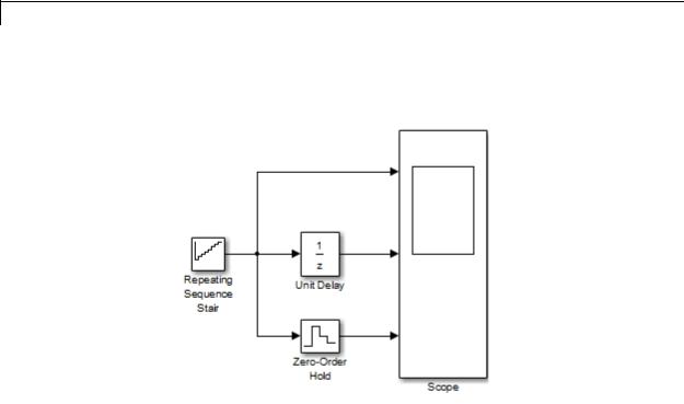
Suppose that you have a model with Unit Delay and Zero-Order Hold blocks, which both use a discrete sample time of 1:
The Repeating Sequence Stair block uses a continuous sample time of 0 to provide input signals to the Unit Delay and Zero-Order Hold blocks.
2-942
Memory
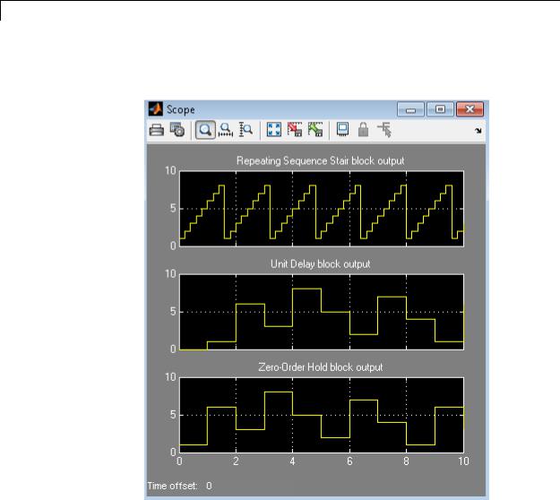
If the model uses a fixed-step solver with a step size of 1, the scope shows the following simulation results:
2-943
Memory
If the model uses a variable-step solver, the scope shows the following simulation results:
The Zero-Order Hold block takes the input value of the Repeating Sequence Stair block at t = 0, 1, 2, ... , 9 and holds each input value for a sample period (1 second). The Unit Delay block applies the same 1-second hold to each input value of the Repeating Sequence Stair block, but also delays each value by a sample period. The Initial conditions
2-944
Memory
Data Type
Support
parameter specifies the output for the Unit Delay block during the first sample period. For more information about sample time, see “What Is Sample Time?” and “Specify Sample Time”.
Solver specification for a model also affects the behavior of the Memory block. For details, see “Examples of Memory Block Usage” on page 2-949.
The Memory block accepts real or complex signals of any data type that Simulink supports, including fixed-point and enumerated data types.
For more information, see “Data Types Supported by Simulink” in the Simulink documentation.
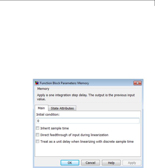
Parameters The Main pane of the Memory block dialog box appears as follows:
and Dialog Box
2-945

Memory
Initial condition
Specify the output at the initial integration step. This value must be 0 when you do not use a built-in input data type. Simulink does not allow the initial output of this block to be inf or NaN.
Inherit sample time
Select to inherit the sample time from the driving block. If you do not select this check box, the block sample time depends on the type of solver for simulating the model.
•If the solver is a variable-step solver, the sample time is continuous but fixed in minor time step: [0, 1].
•If the solver is a fixed-step solver, this [0, 1] sample time converts to the solver step size after sample-time propagation.
Direct feedthrough of input during linearization
Select to output the input during linearization and trim. This selection sets the block mode to direct feedthrough.
Selecting this check box can cause a change in the ordering of states in the model when using the functions linmod, dlinmod, or trim. To extract this new state ordering, use the following commands.
First compile the model using the following command, where model is the name of the Simulink model.
[sizes, x0, x_str] = model([],[],[],'lincompile');
Next, terminate the compilation with the following command.
model([],[],[],'term');
The output argument, x_str, which is a cell array of the states in the Simulink model, contains the new state ordering. When passing a vector of states as input to the linmod, dlinmod, or trim functions, the state vector must use this new state ordering.
2-946
Memory
Treat as a unit delay when linearizing with discrete sample time
Select to linearize the Memory block to a unit delay when the Memory block is driven by a signal with a discrete sample time.
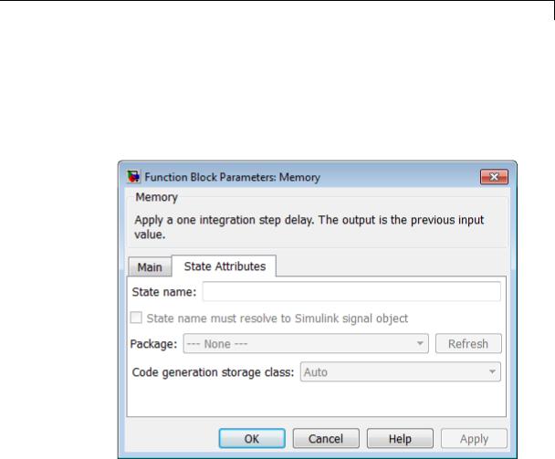
The State Attributes pane of the Memory block dialog box appears as follows:
State name
Use this parameter to assign a unique name to the block state. The default is ' '. When this field is blank, no name is assigned. When using this parameter, remember these considerations:
•A valid identifier starts with an alphabetic or underscore character, followed by alphanumeric or underscore characters.
•The state name applies only to the selected block.
2-947

Memory
This parameter enables State name must resolve to Simulink signal object when you click Apply.
For more information, see “States” in the Simulink Coder documentation.
State name must resolve to Simulink signal object
Select this check box to require that the state name resolve to a Simulink signal object. This check box is cleared by default.
State name enables this parameter.
Selecting this check box disables Code generation storage class.
Package
Select a package that defines the custom storage class you want to apply. If you have defined any packages of your own, click Refresh. This action adds all user-defined packages on your search path to the package list.
Code generation storage class
From the list, select a state storage class.
Auto
Auto is the storage class to use for states that do not need to interface to external code.
ExportedGlobal
The state is stored in a global variable.
ImportedExtern
model_private.h declares the state as an extern variable.
ImportedExternPointer
model_private.h declares the state as an extern pointer.
State name enables this parameter.
2-948
Memory
Examples of Memory Block Usage
Setting this parameter to ExportedGlobal, ImportedExtern, or ImportedExternPointer enables Code generation storage type qualifier.
Code generation storage type qualifier
Specify a Simulink Coder storage type qualifier. The default is ' '. When this field is blank, no qualifier is assigned.
The Simulink Coder product does not check this string for errors. Thus, whatever value you enter appears automatically in the variable declaration.
Setting Code generation storage class to ExportedGlobal,
ImportedExtern, or ImportedExternPointer enables this parameter.
During simulation, the block uses the following values:
•The initial value of the signal object to which the state name is resolved
•Min and Max values of the signal object
See “States” in the Simulink Coder documentation for more information.
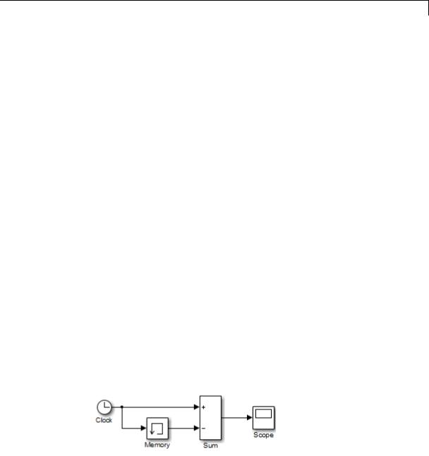
Usage with the Clock Block
The following model shows how to display the step size in a simulation. The Sum block subtracts the time at the previous step, which the Memory block generates, from the current time, which the Clock block generates.
2-949
Memory
Because Inherit sample time is not selected for the Memory block, the block sample time depends on the type of solver for simulating the model. In this case, the model uses a fixed-step solver. Therefore, the sample time of the Memory block is the solver step size, or 1.
If you replace the Memory block with a Unit Delay block, you get the same results. The Unit Delay block inherits a discrete sample time of 1.
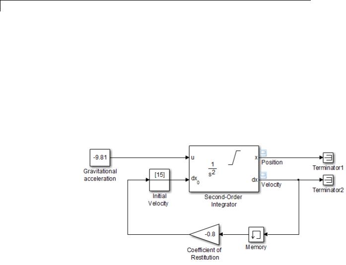
Usage with the Second-Order Integrator Block
The sldemo_bounce model shows how a bouncing ball reacts after being tossed into the air. The dx port of the Second-Order Integrator block and the Memory block capture the velocity of the ball just before it hits the ground.
2-950
Memory
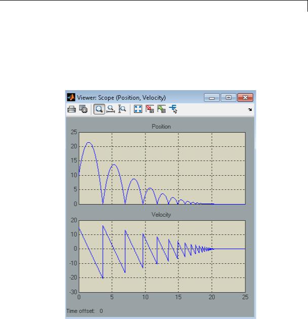
Because Inherit sample time is not selected for the Memory block, the block sample time depends on the type of solver for simulating the model. In this case, the model uses a variable-step (ode23) solver. Therefore, the sample time of the Memory block is continuous but fixed in minor time step: [0, 1]. When you run the model, you get the following results:
If you replace the Memory block with a Unit Delay block, you get the same results. However, a warning also appears due to the discrete Unit Delay block inheriting a continuous sample time.
2-951
Memory
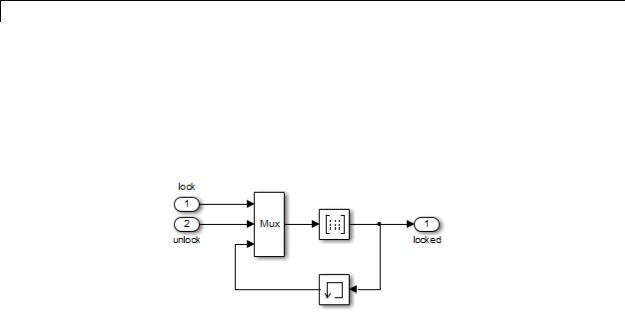
Usage with the Combinatorial Logic Block
The sldemo_clutch model shows how you can use the Memory block with the Combinatorial Logic block to implement a finite-state machine. This construct appears in the Friction Mode Logic/Lockup FSM subsystem.
|
Because Inherit sample time is not selected for the Memory block, |
|
the block sample time depends on the type of solver for simulating the |
|
model. In this case, the model uses a variable-step (ode23) solver. |
|
Therefore, the sample time of the Memory block is continuous but fixed |
|
in minor time step: [0, 1]. |
Bus |
The Memory block is a bus-capable block. The input can be a virtual or |
Support |
nonvirtual bus signal subject to the following restrictions: |
|
• Initial condition must be zero, a nonzero scalar, or a finite numeric |
|
structure. |
|
• If Initial condition is zero or a structure, and you specify a State |
|
name, the input cannot be a virtual bus. |
|
• If Initial condition is a nonzero scalar, you cannot specify a State |
|
name. |
|
For information about specifying an initial condition structure, see |
|
“Specify Initial Conditions for Bus Signals”. |
2-952
Memory
All signals in a nonvirtual bus input to a Memory block must have the same sample time, even if the elements of the associated bus object specify inherited sample times. You can use a Rate Transition block to change the sample time of an individual signal, or of all signals in a bus. See “Nonvirtual Bus Sample Times” and Bus-Capable Blocks for more information.
You can use an array of buses as an input signal to a Memory block. Only the Initial condition parameter (which may be, but does not have to be, a structure) is scalar-expanded to match the dimensions of the array of buses. For details about defining and using an array of buses, see “Combine Buses into an Array of Buses”.
Characteristics |
|
Bus-capable |
Yes, with restrictions as noted above |
|
|
Direct Feedthrough |
No, except when you select Direct |
|
|
|
feedthrough of input during |
|
|
|
linearization |
|
|
Sample Time |
Continuous, but inherited from the |
|
|
|
driving block when you select the |
|
|
|
Inherit sample time check box |
|
|
Scalar Expansion |
Yes, of the Initial condition |
|
|
|
parameter |
|
|
Dimensionalized |
Yes |
|
|
Multidimensionalized |
Yes |
|
|
Zero-Crossing Detection |
No |
See Also |
|
Unit Delay, Zero-Order Hold |
|
2-953

Merge
Purpose |
Combine multiple signals into single signal |
Library |
Signal Routing |
Description |
The Merge block combines its inputs into a single output line whose |
|
value at any time is equal to the most recently computed output of its |
|
driving blocks. You can specify any number of inputs by setting the |
|
block’s Number of inputs parameter. |
|
Use Merge blocks only to interleave input signals that update at |
|
different times into a combined signal in which the interleaved |
|
values retain their separate identities and times. To combine signals |
|
that update at the same time into an array or matrix signal, use a |
|
Concatenate block. |
|
Merge blocks assume that all driving signals share the same signal |
|
memory. The shared signal memory should be accessed only in |
|
mutually exclusive fashion. Therefore, always use alternately executing |
|
subsystems to drive Merge blocks. See “Creating Alternately Executing |
|
Subsystems” for an example. |
|
All signals that connect to a Merge block, or exist anywhere in a network |
|
of Merge blocks, are functionally the same signal, and are therefore |
|
subject to the restriction that a given signal can have at most one |
|
associated signal object. See Simulink.Signal for more information. |
|
Guidelines for Using the Merge Block |
|
When you use the Merge block, follow these guidelines: |
|
• Always use conditionally-executed subsystems to drive Merge blocks. |
|
• Write your control logic to ensure that at most one of the driving |
|
conditionally-executed subsystems executes at any time step. |
|
• Do not connect more than one input of a Merge block to the same |
|
conditionally-executed subsystem. |
|
• Always connect a Merge block to at least two input signals. |
|
• Ensure that all input signals have the same sample time. |
2-954
Merge
•Always set the Initial output parameter of the Merge block, unless the output port of the Merge block connects to another Merge block.
•Do not branch a signal that inputs to a Merge block, if you use the default setting of Classic for the Model Configuration
Parameters > Diagnostics > Underspecified initialization detection parameter. See the last example in “Proper Merge Block Usage” on page 2-955 for additional usage guidelines relating to branched signals.
•For all conditionally-executed subsystem Outport blocks that drive Merge blocks, set the Output when disabled parameter to held.
Proper Merge Block Usage
For each input of a Merge block, the topmost non-atomic and nonvirtual source must be a conditionally-executed subsystem that is not an Iterator Subsystem.
You can use the Model Advisor to check for proper Merge block usage in your model. For more information, see “Check for proper Merge block usage” on page 10-36.
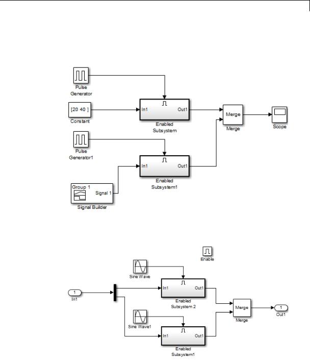
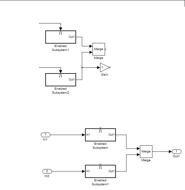
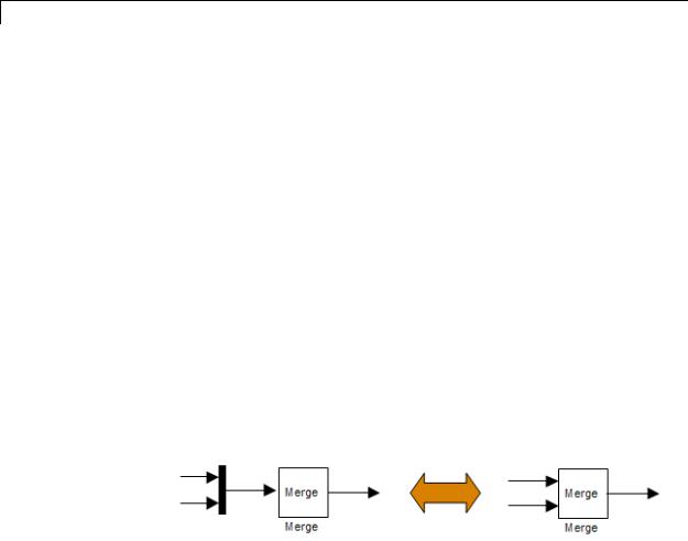
The following schematic shows proper Merge block usage, merging signals from two conditionally-executed subsystems.
2-955
Merge
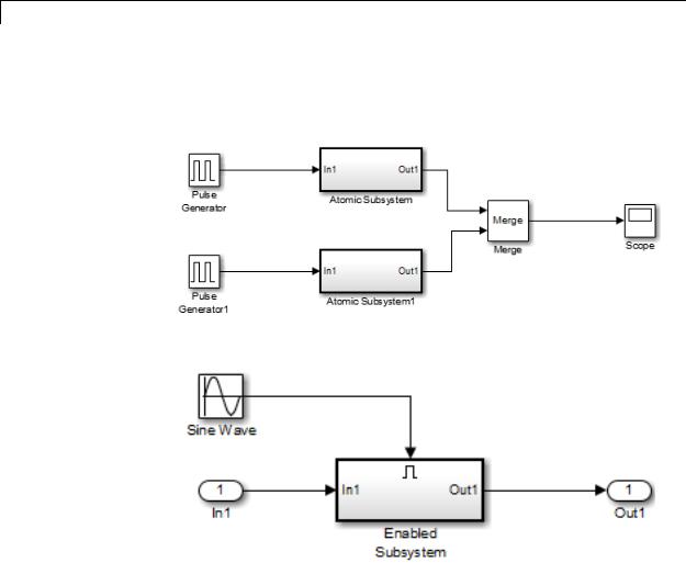
The following example is also a valid Merge block usage, where the topmost nonatomic, nonvirtual source is a conditionally executed subsystem.
Each Atomic Subsystem block contains an enabled subsystem.
2-956
Merge
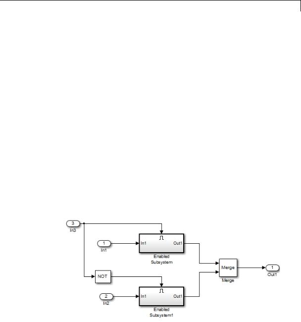
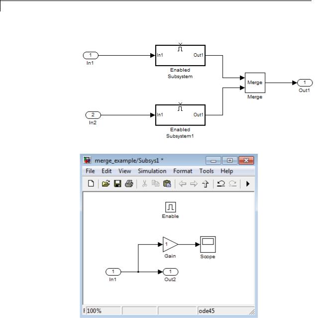
You can also use multiple Merge blocks at different levels of the model hierarchy. The following example contains a Merge block at the model root.
A Merge block is also located inside the Enabled Subsystem block, one level down.
2-957
Merge
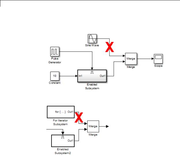
A Merge block cannot connect to a Sine Wave block because that source block is not a conditionally-executed subsystem.
A Merge block cannot connect to a For Iterator Subsystem.
A Merge block cannot connect to a branched signal.
2-958
Merge
X
In the following model, the referenced model has a signal that branches. It inputs to a block in the referenced model and also inputs to the Merge block that is outside of the referenced model.
2-959
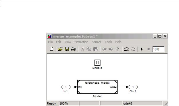
Merge
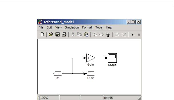
Although the top-level model appears that it would work, the Subsys1 subsystem includes a Model block that references referenced_model.
The referenced model includes a signal that incorrectly branches to a Gain block and to the Out2 Outport block, which connects to the Merge block that is outside of the referenced model.
2-960
Merge
X
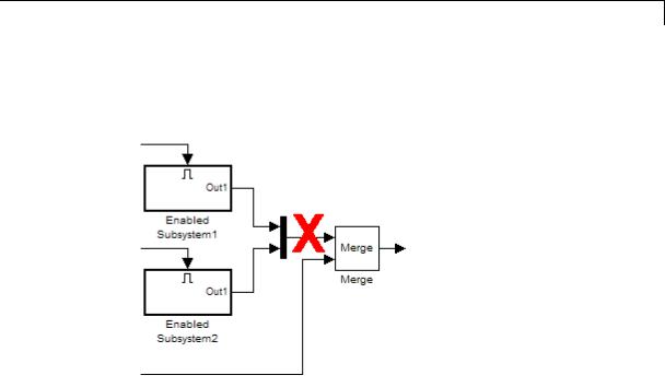
The following example also shows a branched signal in a subsystem that connects to a Merge block, which is not allowed if you use the default setting of Classic for the Model Configuration Parameters > Diagnostics > Underspecified initialization detection parameter.
If you set the Underspecified initialization detection parameter to
Simplified, then the following example does not generate an error. For more information on simplified initialization mode, see “Underspecified initialization detection”.
2-961
Merge
X
2-962
Merge
Initial Output Value
You can specify an initial output value for the Merge block by setting the Initial output parameter. If you do not specify an initial output value and one or more of the driving blocks do, the initial output of the Merge block equals the most recently evaluated initial output of the driving blocks.
When two or more sources initialize the same Merge block, the initialization ordering for these sources may vary. If you leave the initial output unspecified, initialization may be inconsistent for the simulation and the code generation of a model. For example, the following model can produce inconsistent initialization:
•The model contains a Merge block with two inputs: one driven by a Stateflow chart and the other driven by a conditionally executed subsystem (such as an Enabled Subsystem).
•The Merge block Initial output parameter is unspecified (that is, specified as empty matrix ([])).
•The Stateflow chart initializes the output being merged to val1.
•The conditionally executed subsystem initializes the output being merged to different value val2.
•Both the Stateflow chart and the conditionally executed susystem do not execute at the first time step.
Because the initialization ordering may vary, the output of the Merge block at the first time step is val1 if the Stateflow chart initializes last and val2 if the conditionally executed subsystem initializes last. The initialization ordering is different for simulation and code generation.
To address this issue, use one of the following approaches:
•Set the Initial output parameter of the Merge block, unless the output port of the Merge block connects to another Merge block.
2-963
Merge
•Turn on simplified initialization mode: set the Model Configuration
Parameters > Diagnostics > Data Validity > Underspecified initialization detection parameter to Simplified.
To use the Simplified initialization setting, specify the Initial output value for all root Merge blocks. A root Merge block is any Merge block with an output port that does not connect to another Merge block.
To upgrade your model to simplified initialization mode, use the Model Advisor Check consistency of initialization parameters for Outport and Merge blocks check.
For more information on simplified initialization mode, see “Underspecified initialization detection”.
Single-Input Merge
Single-input merge is not supported. Each Merge block must have at least two inputs.
Use Merge blocks only for signals that require merging. If you were previously connecting a Merge block input to a Mux block, use a multi-input Merge block instead.
Input Dimensions and Merge Offsets
The Merge block accepts only inputs of equal dimensions and outputs a signal of the same dimensions as the inputs, unless you select the
Allow unequal port widths parameter.
If you select Allow unequal port widths, the block accepts scalars and vectors (but not matrices) having differing numbers of elements. Further, the block allows you to specify an offset for each input signal relative to the beginning of the output signal. The width of the output signal is
2-964
Merge
max(w1+o1, w2+o2, ... wn+on)
where w1, ... wn are the widths of the input signals and o1, ... on are the offsets for the input signals.
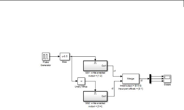
Suppose that you have the following block diagram:
The Merge block has the following output width:
max(2+0,2+1)=3
2-965
Merge
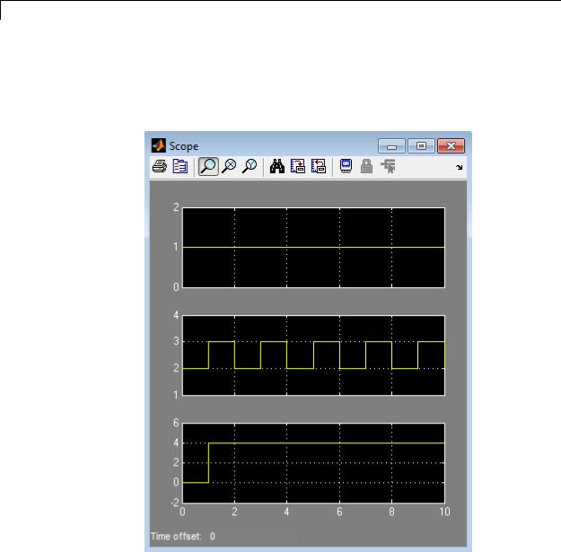
In this example, the offset of v1 is 0 and the offset of v2 is 1. The Merge block maps the elements of v1 to the first two elements of v3 and the elements of v2 to the last two elements of v3. Only the second element of v3 is effectively merged, as shown in the scope output:
2-966
Merge
If you use Simplified Initialization Mode, you must clear the Allow unequal port widths check box. The input port offsets for all input signals must be zero.
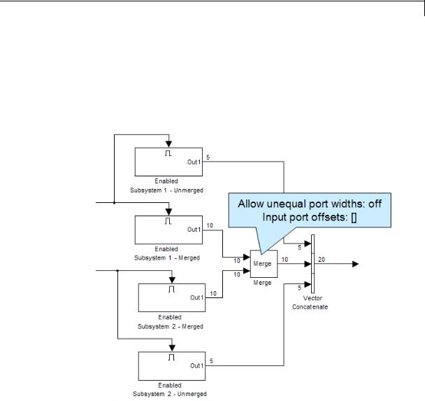
Consider using Merge blocks only for signal elements that require true merging. Other elements can be combined with merged elements using the Concatenate block, as shown in the following example.
For more information on simplified initialization mode, see “Underspecified initialization detection”.
2-967
Merge
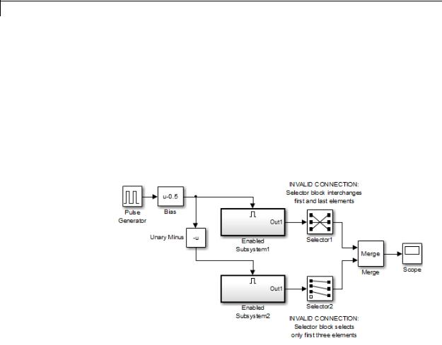
Combining or Reordering of Input Signals
A Merge block does not accept input signals whose elements have been reordered or partially selected. In addition, you should not connect input signals to the Merge block that have been combined outside of a conditionally-executed subsystem.
For example, in the following block diagram, the Merge block does not accept the output of the first Selector block because the Selector block interchanges the first and last elements of the vector signal. Similarly, the Merge block does not accept the output of the second Selector block because the Selector block selects only the first three elements.
2-968
Merge
If you use simplified initialization mode, the following arrangement is not allowed because two signals are being combined outside of a conditionally-executed subsystem.
2-969
Merge
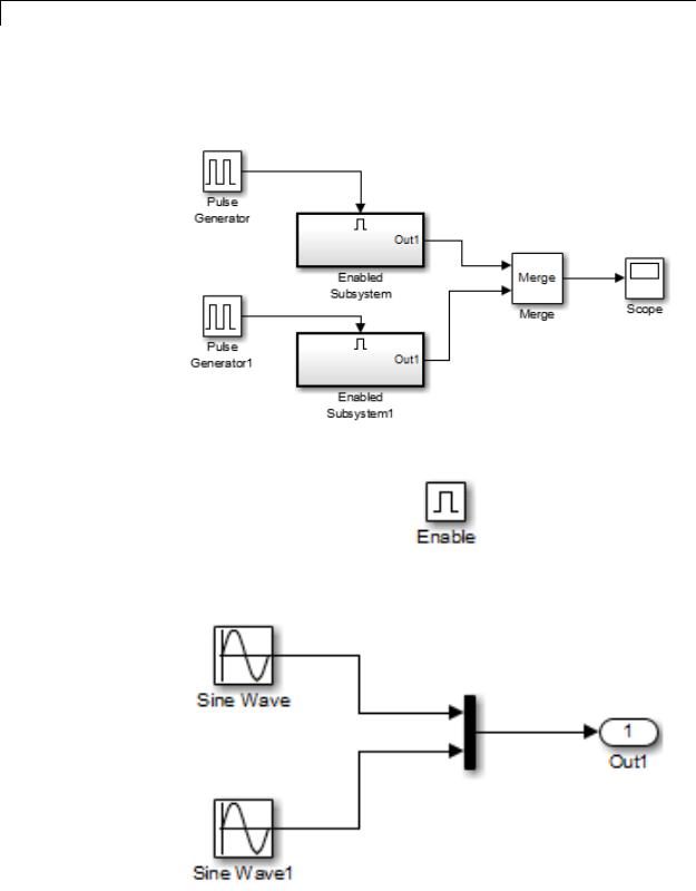
You can, however, combine or reorder Merge block input signals within a conditionally-executed subsystem. For example, the following model is valid.
Each Enabled Subsystem contains the following blocks.
2-970

Merge
Conditionally-Executed Subsystem Outport Reset
The Outports of conditionally-executed subsystems being merged should not reset when disabled. This action can cause multiple subsystems to update the Merge block at the same time. Specifically, the disabled subsystem updates the Merge block by resetting its output, while the enabled subsystem updates the Merge block by computing its output.
To prevent this behavior, set the Outport block parameter Output when disabled to held for each conditionally-executed subsystem being merged.
Note If you are using Simplified Initialization Mode, you must set the Outport block parameter Output when disabled to held.
2-971
Merge
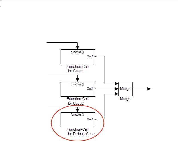
Instead of resetting the subsystem output when it is disabled, add an additional subsystem for the default case, and use control logic to run this subsystem if nothing else runs. For example, see the following block layout:
For more information on simplified initialization mode, see “Underspecified initialization detection”.
Merging S-Function Outputs
The Merge block can merge a signal from an S-Function block only if the memory used to store the S-Function block’s output is reusable. Simulink software displays an error message if you attempt to update or simulate a model that connects a nonreusable port of an S-Function
2-972
Merge
Data Type
Support
block to a Merge block. See ssSetOutputPortOptimOpts for more information.
The Merge block accepts real or complex signals of any data type that Simulink supports, including fixed-point and enumerated data types. All inputs must be of the same data type and numeric type.
For more information, see “Data Types Supported by Simulink” in the Simulink documentation.
2-973
Merge
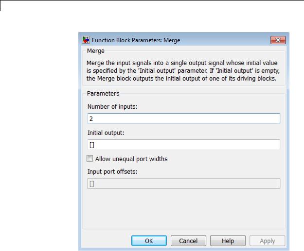
Parameters and Dialog Box
Number of inputs
Specify the number of input ports to merge.
Initial output
Specify the initial value of output. If unspecified, the initial output equals the initial output, if any, of one of the driving blocks. You cannot set the initial output of this block to inf or NaN.
2-974

Merge
Allow unequal port widths
|
Select this check box to allow the block to accept inputs having |
|
different numbers of elements. |
|
Input port offsets |
|
Enter a vector to specify the offset of each input signal relative to |
|
the beginning of the output signal. |
Bus |
The Merge block is a bus-capable block. The inputs can be virtual or |
Support |
nonvirtual bus signals subject to the following restrictions: |
|
• The number of inputs must be greater than one. |
|
• Initial output must be zero, a nonzero scalar, or a finite numeric |
|
structure. |
|
• Allow unequal port widths must be disabled. |
|
• All inputs to the merge must be buses and must be equivalent (same |
|
hierarchy with identical names and attributes for all elements). |
|
For information about specifying an initial condition structure, see |
|
“Specify Initial Conditions for Bus Signals”. |
|
All signals in a nonvirtual bus input to a Merge block must have the |
|
same sample time, even if the elements of the associated bus object |
|
specify inherited sample times. You can use a Rate Transition block to |
|
change the sample time of an individual signal, or of all signals in a bus. |
|
See “Composite Signals” and Bus-Capable Blocks for more information. |
|
You can use an array of buses as an input signal to a Merge block. For |
|
details about defining and using an array of buses, see “Combine Buses |
|
into an Array of Buses”. Using an array of buses with a Merge block |
|
involves these limitations: |
|
• Allow unequal port widths — Clear this parameter. |
|
• Number of inputs — Set to a value of 2 or greater. |
2-975

Merge
•Initial condition — Only this parameter (which might be, but does not have to be, a structure) is scalar-expanded to match the dimensions of the array of buses.
Characteristics |
Bus-capable |
Yes, with restrictions as noted |
|
|
above |
|
Direct Feedthrough |
Yes |
|
Sample Time |
Inherited from the driving block |
|
Scalar Expansion |
No |
|
Dimensionalized |
Yes |
|
Multidimensionalized |
Yes |
|
Zero-Crossing Detection |
No |
|
|
|
2-976

MinMax
Purpose |
Output minimum or maximum input value |
Library |
Math Operations |
Description |
The MinMax block outputs either the minimum or the maximum |
|
element or elements of the inputs. You can choose the function to apply |
|
by selecting one of the choices from the Function parameter list. |
|
If the block has one input port, the input must be a scalar or a vector. |
|
The block outputs a scalar equal to the minimum or maximum element |
|
of the input vector. |
|
If the block has multiple input ports, all nonscalar inputs must have |
|
the same dimensions. The block expands any scalar inputs to have the |
|
same dimensions as the nonscalar inputs. The block outputs a signal |
|
having the same dimensions as the input. Each output element equals |
|
the minimum or maximum of the corresponding input elements. |
|
The MinMax block ignores any input value that is NaN, except when |
|
every input value is NaN. When all input values are NaN, the output is |
|
NaN, either as a scalar or the value of each output vector element. |
Data Type |
The MinMax block accepts and outputs real signals of the following |
Support |
data types: |
|
• Floating point |
|
• Built-in integer |
|
• Fixed point |
|
For more information, see “Data Types Supported by Simulink” in the |
|
Simulink documentation. |
2-977
MinMax
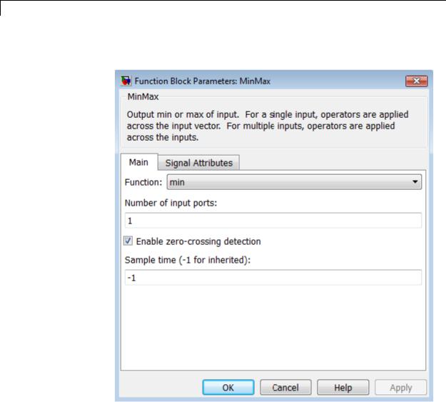
Parameters The Main pane of the MinMax block dialog box appears as follows:
and Dialog Box
Function
Specify whether to apply the function min or max to the input.
Number of input ports
Specify the number of inputs to the block.
2-978

MinMax
Enable zero-crossing detection
Select to enable zero-crossing detection. For more information, see “Zero-Crossing Detection” in the Simulink documentation.
Sample time (-1 for inherited)
Specify the time interval between samples. To inherit the sample time, set this parameter to -1. See “Specify Sample Time” in the online documentation for more information.
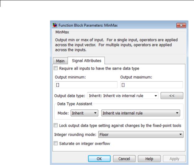
The Signal Attributes pane of the MinMax block dialog box appears as follows:
2-979
MinMax
Require all inputs to have the same data type
Select this check box to require that all inputs have the same data type.
2-980

MinMax
Output minimum
Specify the minimum value that the block should output. The default value is [] (unspecified). Simulink software uses this value to perform:
•Simulation range checking (see “Signal Ranges”)
•Automatic scaling of fixed-point data types
Output maximum
Specify the maximum value that the block should output. The default value is[] (unspecified). Simulink software uses this value to perform:
•Simulation range checking (see “Signal Ranges”)
•Automatic scaling of fixed-point data types
Output data type
Specify the output data type. You can set it to:
•A rule that inherits a data type, for example, Inherit: Inherit via back propagation
•The name of a built-in data type, for example, single
•The name of a data type object, for example, a
Simulink.NumericType object
•An expression that evaluates to a data type, for example, fixdt(1,16,0)
Click the Show data type assistant button  to display the Data Type Assistant, which helps you set the
Output data type parameter.
See “Specify Block Output Data Types” in the Simulink User’s Guide for more information.
2-981

MinMax
Lock output data type setting against changes by the fixed-point tools
Select to lock the output data type setting of this block against changes by the Fixed-Point Tool and the Fixed-Point Advisor. For more information, see “Use Lock Output Data Type Setting”.
Integer rounding mode
Specify the rounding mode for fixed-point operations. For more information, see “Rounding”. in the Simulink Fixed Point documentation.
Saturate on integer overflow
|
Action |
Reasons for Taking |
What Happens for |
Example |
|
|
This Action |
Overflows |
|
|
Select this |
Your model has |
Overflows saturate to |
An overflow associated |
|
check box. |
possible overflow, |
either the minimum |
with a signed 8-bit |
|
|
and you want explicit |
or maximum value |
integer can saturate to |
|
|
saturation protection |
that the data type can |
–128 or 127. |
|
|
in the generated code. |
represent. |
|
|
Do not select |
You want to optimize |
Overflows wrap to the |
The number 130 does |
|
this check |
efficiency of your |
appropriate value that |
not fit in a signed 8-bit |
|
box. |
generated code. |
is representable by the |
integer and wraps to |
|
|
You want to avoid |
data type. |
–126. |
|
|
|
|
|
|
|
overspecifying how |
|
|
|
|
a block handles |
|
|
|
|
out-of-range signals. |
|
|
|
|
For more information, |
|
|
|
|
see “Checking for |
|
|
|
|
Signal Range Errors”. |
|
|
|
|
When you select this check box, saturation applies to every |
||
|
|
internal operation on the block, not just the output or result. |
||
|
|
Usually, the code generation process can detect when overflow is |
||
|
|
not possible. In this case, the code generator does not produce |
||
|
|
saturation code. |
|
|
2-982
MinMax
Examples The sldemo_fuelsys model shows how to use the MinMax block.
In the Engine Gas Dynamics/Throttle & Manifold/Throttle subsystem, the MinMax block uses the min operator:
In the Engine Gas Dynamics/Mixing & Combustion subsystem, the
MinMax block uses the max operator:
2-983

MinMax
Characteristics |
|
Direct Feedthrough |
Yes |
|
|
Sample Time |
Specified in the Sample time |
|
|
|
parameter |
|
|
Scalar Expansion |
Yes, of the inputs |
|
|
Dimensionalized |
Yes |
|
|
Multidimensionalized |
Yes |
|
|
Zero-Crossing Detection |
Yes, if enabled |
See Also |
|
MinMax Running Resettable |
|
2-984
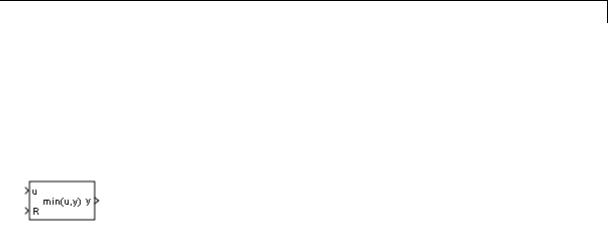
MinMax Running Resettable
Purpose |
Determine minimum or maximum of signal over time |
Library |
Math Operations |
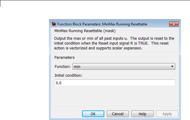
Description |
The MinMax Running Resettable block outputs the minimum or |
|
maximum of all past inputs u. You specify whether the block outputs |
|
the minimum or the maximum with the Function parameter. |
|
The block can reset its state based on an external reset signal R. When |
|
the reset signal R is TRUE, the block resets the output to the value of |
|
the Initial condition parameter. |
|
The input can be a scalar, vector, or matrix signal. If you specify a |
|
scalar Initial condition parameter, the block expands the parameter |
|
to have the same dimensions as a nonscalar input. The block outputs a |
|
signal having the same dimensions as the input. Each output element |
|
equals the running minimum or maximum of the corresponding input |
|
elements. |
Data Type |
The MinMax Running Resettable block accepts and outputs real signals |
Support |
of any numeric data type that Simulink supports, except Boolean. The |
|
MinMax Running Resettable block supports fixed-point data types. |
|
For more information, see “Data Types Supported by Simulink” in the |
|
Simulink documentation. |
2-985
MinMax Running Resettable
Parameters and Dialog Box
Characteristics
Function
Specify whether the block outputs the minimum or the maximum.
Initial condition
Specify initial condition.
Direct Feedthrough |
Yes |
Scalar Expansion |
Yes |
|
|
See Also |
MinMax |
2-986

Model, Model Variants
Purpose |
Include model as block in another model |
Library |
Ports & Subsystems |
Description |
|
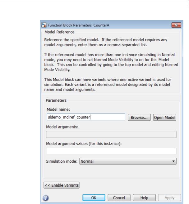
The Model block allows you to include a model as a block in another model. The included model is called a referenced model, and the model containing it (via the Model block) is called the parent model.
The Model block displays input ports and output ports corresponding to the top-level input and output ports of the referenced model. Use these ports allow you to connect the referenced model to other blocks in the parent model. See “Model Reference” for more information.
A Model block can specify the referenced model:
•Statically, as a Model block parameter value, which must name the model literally
•Dynamically, depending on base workspace values
A Model Variants block is a Model block with variants enabled. The Model block parameter dialog box contains the Enable Variants button by default. If you click the Enable Variants button, the Model Variants block parameter dialog opens. The Model Variants block parameter dialog contains the Disable Variants button by default. Therefore, you can use either the Model block or Model Variants block for implementing model variants. For more information about how
to specify a referenced model for multiple specifications, see “Set Up Model Variants”.
2-987

Model, Model Variants
Data Type
Support
By default, the contents of a referenced model are user-visible, but you can hide the contents as described in “Protected Model”.
A signal that connects to a Model block is functionally the same signal outside and inside the block. A given signal can have at most one associated signal object, so the signal connected to the Model block cannot have a signal object in both the parent and the referenced models. For more information, see Simulink.Signal.
The Model block supports signal label propagation. For details specific to model referencing and model variants, see:
•“Processing for Referenced Models”
•“Processing for Variants and Configurable Subsystems”
Determined by the root-level inputs and outputs of the model referenced by the Model block.
2-988
Model, Model Variants
Parameters and
Dialog |
• “Model name” on page 2-991 |
Box |
• “Model arguments” on page 2-992 |
|
• “Model argument values (for this instance)” on page 2-993 |
2-989

Model, Model Variants
•“Simulation mode” on page 2-994
•“Enable variants” on page 2-996
•“Variant choices” on page 2-998
•“Variant object” on page 2-1000
•“Condition” on page 2-1001
•“Model name” on page 2-1002
•“Model name” on page 2-1003
•“Model arguments” on page 2-1004
•“Model argument values (for this instance)” on page 2-1005
•“Simulation mode” on page 2-1006
•“Override variant conditions and use following variant” on page 2-1008
•“Variant” on page 2-1009
•“Generate preprocessor conditionals” on page 2-1010
•“Disable variants” on page 2-1010
2-990

Model, Model Variants
Model name
Name of the model this block references.
Settings
Default: <Enter Model Name>
The value must be a valid MATLAB identifier.
The extension, for example, .SLX, is optional.
Tips
•To navigate to the model that you want to reference from this block, use the Browse button to the right of the Model name parameter.
•To confirm that the model you specify is the one you intended, you can use the Open Model button to the right of the Model name parameter.
Command-Line Information
Parameter: ModelNameDialog
Type: string
Value: Any valid value
Default: The name of the referenced model exactly as you typed it in, with any surrounding whitespace removed. When you set ModelNameDialog programmatically or with the GUI, Simulink
automatically sets the values of ModelName and ModelFile based on the value of ModelNameDialog.
2-991

Model, Model Variants
Model arguments
Display model arguments accepted by the model referenced by this block.
Declaring a variable to be a model argument allows each instance of the model to use a different value for that variable.
Settings
Default: ''
This is a read-only parameter that displays model arguments for the model referenced by this block. To create model arguments, refer to “Using Model Arguments”.
2-992
Model, Model Variants
Model argument values (for this instance)
Specify values to be passed as model arguments to the model referenced by this block each time the simulation invokes the model.
Settings
Enter the values in this parameter as a comma-separated list in the same order as the corresponding argument names appear in the Model arguments field.
Command-Line Information
Parameter: ParameterArgumentValues
Type: string
Value: Any valid value
Default: ''
2-993

Model, Model Variants
Simulation mode
Set the simulation mode for the model referenced by this block. This setting specifies whether to simulate the model by generating and executing code or by interpreting the model in Simulink.
Settings
Default: Accelerator
Accelerator
Creates a MEX-file for the submodel, then executes the submodel by running the S-function.
Normal
Executes the submodel interpretively, as if the submodel were an atomic subsystem implemented directly within the parent model.
Software-in-the-loop (SIL)
This option requires Embedded Coder software. Generates production code using model reference target for the submodel. This code is compiled for, and executed on, the host platform.
Processor-in-the-loop (PIL)
This option requires Embedded Coder software. Generates production code using model reference target for the submodel. This code is compiled for, and executed on, the target platform. A documented target connectivity API supports exchange of data between the host and target at each time step during the PIL simulation.
Command-Line Information
Parameter: SimulationMode
Type: string
Value: 'Accelerator' | 'Normal' | 'Software-in-the-loop
(SIL)' | 'Processor-in-the-loop (PIL)' Default: 'Accelerator'
See Also
•“Using Model Arguments”
•“Choosing a Simulation Mode”
2-994

Model, Model Variants
•“Overview of the Target Connectivity API”
•“Numerical Equivalence Testing”
2-995

Model, Model Variants
Enable variants
Enables variants and opens the Model Variants block parameter dialog box, which is hidden by default. The Model Variants block parameter dialog box is the default block parameter dialog box for the Model Variants block.
Settings
Default: Disabled
Dependencies
This button enables the Model Variants Sections, which include:
Variant choices table, Model parameters for the chosen variant in table section, parameters to override variants, and a Code generation section.
The following example shows the Model variants options from the example model sldemo_mdlref_variants.
2-996
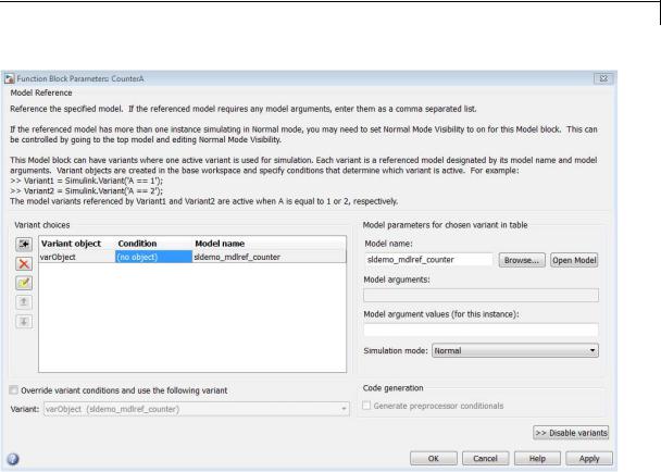
Model, Model Variants
See Also
“Set Up Model Variants”
“Set Up Model Variants”
2-997
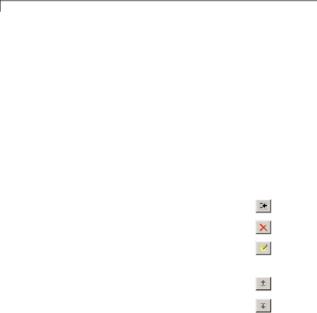
Model, Model Variants
Variant choices
Displays a table of Simulink.Variant objects, associated model names, and conditions, which are Boolean expressions that determine which is the active variant.
Settings
Default: The table has a row for each variant object in the base workspace. The Variant choices table includes the name of each Variant object, its associated Condition, and the corresponding
Model name.
Use the Add a new variant object button to add a new row to the table. See the description of the Variant object, Condition and Model name table columns for information about how to set values for table rows.
Tips
You can use buttons to the left of the Variant choices table to modify the table.
|
Function |
Button |
|
|
Add a new variant: Add a new, empty row below |
|
|
|
the currently selected row |
|
|
|
|
|
|
|
Delete selected variant: Delete the currently |
|
|
|
selected row. (Models and objects are not affected.) |
|
|
|
Create/Edit selected variant object: Creates a |
|
|
|
Simulink.Variant object in the base workspace and |
|
|
|
opens the Simulink.Variant object parameter dialog |
|
|
|
in order to specify the variant Condition. |
|
|
|
Move variant up: Move the currently selected row |
|
|
|
up one slot in the table |
|
|
|
Move variant down: Move the currently selected |
|
|
|
row up one slot in the table |
|
|
|
|
|
|
2-998

Model, Model Variants
Dependency
Enable variants enables this parameter.
Command-Line Information
Parameter: Variants Type: array
Value: array of variant structures where each element specifies one variant. The structure fields are:
•variant.Name (string) — The name of the Simulink.Variant object that represents the variant to which this element applies.
•variant.ModelName (string) — The name of the referenced model associated with the specified variant object in this Model block.
•variant.ParameterArgumentNames (string) — Read-only string containing the names of the model arguments for which the Model block must supply values.
•variant.ParameterArgumentValues (string) — The values to supply for the model arguments when this variant is the active variant.
•variant.SimulationMode (string) — The execution mode to use when this variant is the active variant.
-Possible values are 'Accelerator' | 'Normal' | 'Software-in-the-loop (SIL)' | 'Processor-in-the-loop
(PIL)'
See Also
“Configuring the Model Variants Block”
2-999

Model, Model Variants
Variant object
Display the Simulink.Variant objects in the base workspace or enter a variant object name in a new row.
Settings
Default: Variant1
To enter a variant object name, double-click a Variant object cell in a new row and type in the variant object name.
Dependency
Enable variants enables this parameter.
Command-Line Information
Structure field: Represented by the variant.Name field in the Variants parameter structure
Type: string
Value: name of the Simulink.Variant object that represents the variant to which this element applies.
Default: ''
See Also
•“About Variant Objects”
•Simulink.Variant
2-1000

Model, Model Variants
Condition
Display the condition for the Simulink.Variant object.
Settings
This read-only field displays the condition for the associated model variant in the base workspace. Click the Edit selected variant object button to specify the condition for the selected variant object.
Tips
The variant condition must be a Boolean expression that references at least one base workspace variable or parameter. For example, FUEL==2 && EMIS==1. Do not surround the condition with parentheses or single quotes. The expression can include:
•MATLAB variables defined in the base workspace
•Simulink parameter objects defined in the base workspace
•Scalar variables
•Enumerated values
•Operators ==, !=, &&, ||, ~
•Parentheses for grouping
Note To control variants using meaningful readable names, use a Simulink.Parameter object of enumerated type to define the variant condition.
Dependency
Enable variants enables this parameter.
See Also
“Configuring the Model Variants Block”
2-1001

Model, Model Variants
Model name
Display or enter the name of the model associated with the variant object in the Variant choices table.
Settings
Default: ''
Double-click the table cell to enter a model name. The name must be a valid MATLAB identifier.
The extension, for example, .SLX, is optional.
Tips
You can type the model name into the table, or you can use the Model parameters for chosen variant in table controls to find and open models:
•To navigate to the model that you want to reference for the selected variant in the table, click the Browse button to the right of the
Model name edit box.
•To confirm that the model you specify is the one you intended, click the Open Model button to the right of the Model name edit box.
Dependency
Enable variants enables this parameter.
Command-Line Information
Structure field: represented by the variant.ModelName field in the Variants parameter structure
Type: string
Value: any valid value
Default: name of the referenced model exactly as you typed it, with any surrounding white space removed. When you set the model name programmatically or with the GUI, Simulink automatically sets the values of ModelName and ModelFile based on the value of
ModelNameDialog.
See Also
“Set Up Model Variants”
2-1002
Model, Model Variants
Model name
Display or enter the name of the model associated with the selected variant object in the Variant choices table.
Settings
Default: ''
Must be a valid MATLAB identifier.
The extension, for example, .SLX, is optional.
Tips
You can type the model name in either the table cell or the Model name edit box for the selected variant in the table. Use the controls to find and open models as follows:
•To navigate to the model that you want to reference from this block, use the Browse button to the right of the Model name parameter.
•To confirm that the model you specify is the one you intended, you can use the Open Model button to the right of the Model name parameter.
Dependency
Enable variants enables this parameter.
Command-Line Information
Structure field: represented by the variant.ModelName field in the Variants parameter structure
Type: string
Value: any valid value
Default: name of the referenced model exactly as you typed it, with any surrounding white space removed. When you set the model name programmatically or with the GUI, Simulink automatically sets the values of ModelName and ModelFile based on the value of
ModelNameDialog.
See Also
“Set Up Model Variants”
2-1003

Model, Model Variants
Model arguments
Display model arguments for the model variant object highlighted in the Variant choices table.
Declaring a variable to be a model argument allows each instance of the model to use a different value for that variable.
Settings
Default: ''
This is a read-only parameter that displays model arguments for the variant object highlighted in the Variant choices table. To create model arguments, refer to “Using Model Arguments”.
Dependency
Enable variants enables this parameter.
Command-Line Information
Structure field: Represented by the variant.ParameterArgumentNames field in the Variants parameter structureOneArgName
Type: string
Value: Enter model arguments as a comma separated list
Default: ''
See Also
•“Using Model Arguments”
•“Set Up Model Variants”
2-1004

Model, Model Variants
Model argument values (for this instance)
Specify values to be passed as model arguments to for the model variant object highlighted in the Variant choices table, each time the simulation invokes the model.
Settings
Enter the values in this parameter as a comma-separated list in the same order as the corresponding argument names appear in the Model arguments field.
Dependency
Enable variants enables this parameter.
Command-Line Information
Structure field: Represented by the
variant.ParameterArgumentValues field in the Variants parameter structureOneArgName
Type: string
Value: Any valid value
Default: ''
See Also
•“Using Model Arguments”
•“Set Up Model Variants”
2-1005

Model, Model Variants
Simulation mode
Set the simulation mode for the model variant object highlighted in the Variant choices table. This setting specifies whether to simulate the model by generating and executing code or by interpreting the model in Simulink.
Settings
Default: Accelerator
Accelerator
Creates a MEX-file for the submodel, then executes the submodel by running the S-function.
Normal
Executes the submodel interpretively, as if the submodel were an atomic subsystem implemented directly within the parent model.
Software-in-the-loop (SIL)
This option requires Embedded Coder software. Generates production code using model reference target for the submodel. This code is compiled for, and executed on, the host platform.
Processor-in-the-loop (PIL)
This option requires Embedded Coder software. Generates production code using model reference target for the submodel. This code is compiled for, and executed on, the target platform. A documented target connectivity API supports exchange of data between the host and target at each time step during the PIL simulation.
Dependency
Enable variants enables this parameter.
Command-Line Information
Structure field: Represented by the variant.SimulationMode field in the Variants parameter structure
Type: string
Value: 'Accelerator' | 'Normal'| 'Software-in-the-loop (SIL)' | 'Processor-in-the-loop (PIL)'
2-1006

Model, Model Variants
Default: 'Accelerator'
See Also
•“Using Model Arguments”
•“Choosing a Simulation Mode”
•“Numerical Equivalence Testing”
•“Set Up Model Variants”
2-1007

Model, Model Variants
Override variant conditions and use following variant
Specify whether to override the variant conditions and make the specified Variant parameter the active variant.
Settings
Default: Off
 On
On
Override the variant conditions and set the active variant to the value of the Variant parameter
 Off
Off
Determine the active variant by the value of the variant conditions
Tip
Both this GUI parameter and the Variant GUI parameter (following) use the same API parameter, OverrideUsingVariant.
Dependencies
Enable variants enables this parameter.
This parameter enables Variant.
Command-Line Information
Parameter: OverrideUsingVariant
Type: string
Value: '' if no overriding variant object is specified, or the name of the overriding variant object
Default: ''
See Also
“Overriding Variant Conditions”
2-1008

Model, Model Variants
Variant
Specify the variant object name associated with the model to use if you select Override variant conditions and use the following variant.
Settings
Default: ''
Must be a valid MATLAB identifier.
Tips
•You can use the Variant edit box pulldown list to scroll a list of all variant objects currently in the base workspace, and their associated models.
•Both this GUI parameter and the Override variant conditions and use following variant GUI parameter (above) use the same API parameter, OverrideUsingVariant.
Dependencies
Enable variants and Override variant conditions and use the following variant enable this parameter.
Command-Line Information
Parameter: OverrideUsingVariant
Type: string (read-only)
Value: Name of the Simulink.Variant object
See Also
•“Overriding Variant Conditions”
•Simulink.Variant
2-1009

Model, Model Variants
Generate preprocessor conditionals
Control whether generated code contains preprocessor conditionals. This check box is relevant only to code generation, and has no effect on the behavior of a model in Simulink. See “Generate Preprocessor Conditionals for Variant Systems” for more information.
Settings
Default: Disabled
Dependencies
•The check box is available for generating only ERT targets.
•Override variant conditions and use following variant is cleared ('off')
•Model Configuration Parameters > Optimization > Inline parameters is selected ('on')
•Model Configuration Parameters > Code Generation > Interface > Generate preprocessor conditionals is set to Use local settings.
Command-Line Information
Parameter: GeneratePreprocessorConditionals
Type: string
Value: 'off' | 'on'
Default: 'off'
See Also
“Variant Systems”
Disable variants
Disable model reference variants and hide the Model Variants Section. The block retains any information you have entered and approved
by clicking Apply or OK. For more information, see “Disabling and Enabling Model Variants”.
Command-Line Information
Parameter: Variant
Type: string
2-1010

Model, Model Variants
Navigating
a Model
Block
Model
Blocks
and Direct
Feedthrough
Value: 'off' | 'on'
Default: 'off'
When you double-click a Model block, the block behaves differently compared to other blocks. This customized behavior depends on the current status of the Model block:
•Double-clicking the prototype Model block in the Ports & Subsystems library opens its Block Parameters dialog box for inspection, but does not allow you to specify parameter values.
•Double-clicking an unresolved Model block opens its Block Parameters dialog box. You can then resolve the block by specifying a Model name.
•Double-clicking a resolved Model block opens the model that the block references. You can also open the model by choosing Open Model from the Context or Edit menu.
To display the Block Parameters dialog box for a resolved Model block, choose Model Reference Parameters from the Context or Edit menu.
When a Model block is part of a cycle, and the block is a direct feedthrough block, an algebraic loop can result. An algebraic loop in a model is not necessarily an error, but it may not give the expected results. See:
•“Algebraic Loops” for information about direct feedthrough and algebraic loops.
•“Highlighting Algebraic Loops Using the Algebraic Loop Diagnostic” for information about seeing algebraic loops graphically
•“Display Algebraic Loop Information” for information about tracing algebraic loops in the debugger.
•The “Diagnostics Pane: Solver” pane “Algebraic loop” option for information about detecting algebraic loops automatically.
2-1011

Model, Model Variants
Direct Model Block Feedthrough Caused by Submodel Structure
A Model block may be a direct feedthrough block due to the structure of the referenced model. Where direct feedthrough results from submodel structure, and causes an unwanted algebraic loop, you can:
•Automatically eliminate the algebraic loop using techniques described in:
-
-
-
“Minimize algebraic loop”
“Minimize algebraic loop occurrences”
“How Simulink Eliminates Artificial Algebraic Loops”
•Manually insert one or more Unit Delay blocks as needed to break the algebraic loop.
Direct Model Block Feedthrough Caused by Model Configuration
ERT-based targets provide the option Model Configuration
Parameters > Code Generation > Interface > Single output/update function. This option controls whether generated code has separate output and update functions, or a combined output/update function. See:
•“Embedded Model Functions” for information about separate and combined output and update functions.
•“Single output/update function” for information about specifying whether code has separate or combined functions.
When Single output/update function is enabled (the default), a Model block has a combined output/update function. The function makes the block a direct feedthrough block for all inports, regardless of the structure of the referenced model. Where an unwanted algebraic loop results, you can:
2-1012
Model, Model Variants
•Disable Single output/update function. The code for the Model block then has separate output and update functions, eliminating the direct feedthrough and hence the algebraic loop.
•Automatically eliminate the algebraic loop using techniques described in:
-
-
-
“Minimize algebraic loop”
“Minimize algebraic loop occurrences”
“How Simulink Eliminates Artificial Algebraic Loops”
•Manually insert one or more Unit Delay blocks as needed to break the algebraic loop.
Characteristics
See Also
Direct Feedthrough |
If “Single output/update function” |
|
is enabled (the default), a Model |
|
block is a direct feedthrough block |
|
regardless of the structure of the |
|
referenced model. |
|
If “Single output/update function” is |
|
disabled, a Model block may or may |
|
not be a direct feedthrough block, |
|
depending on the structure of the |
|
referenced model. |
Scalar Expansion |
Depends on model referenced by this |
|
block. |
Multidimensionalized |
Yes |
|
|
•“Model Reference”
•“Set Up Model Variants”
2-1013

Model Info
Purpose |
Display model properties and text in model |
Library |
Model-Wide Utilities |
Description |
The Model Info block displays model properties and text about a model |
|
on the mask of the block. Use the Model Info block dialog box to specify |
|
the content and format of the text that the block displays. You can |
|
select model properties to display on the block. In the text displayed on |
|
the block mask, Simulink replaces the property name with the current |
|
value of the property in the model. |
Data Type
Support
Not applicable.
2-1014
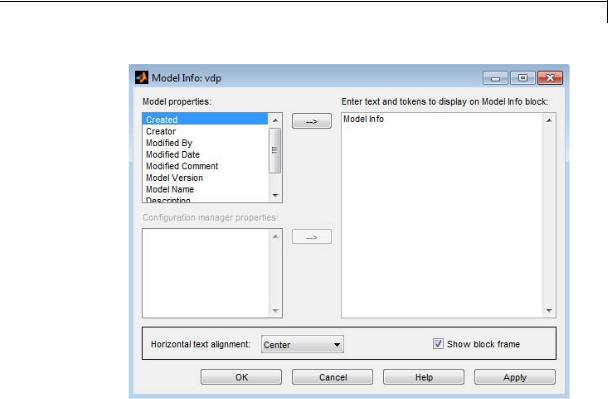
Model Info
Parameters |
|
|
and |
Specify Text and Properties to Display |
|
Dialog |
||
Use the Enter text and tokens to display on Model Info block edit |
||
Box |
||
|
box to specify the text and properties to display. |
|
|
• In the edit box, enter any text you want to display on the block mask. |
|
|
Edit the default text Model Info. |
|
|
• To display a model property on the block mask, select a property in |
|
|
the Model properties list and click the right arrow button. |
|
|
The block adds a token of the form %<modelpropertyname> to the |
|
|
edit box. In the text the block mask displays, Simulink will replace |
|
|
the token with the value of the property. |
|
|
1 For example, if you select Model Version in the Model |
|
|
properties list and click the right arrow button, then the token |
2-1015

Model Info
%<ModelVersion>
appears in the right edit box.
2You could add some explanatory text before the model property, e.g. “Model version is:”.
3When you click Apply or OK, Simulink displays your new text and the current value of the model property on the block mask in the Model Editor like this example:
Model version is: 1.6
See “Version Information Properties” for descriptions of the model properties.
Caution
Using third-party source control tool keyword expansion within model properties tokens might corrupt your model files when you submit them. See “Register Model Files with Source Control Tools”.
If you save your model in SLX format, third-party tools cannot perform keyword substitution. Any information in the model file from such third-party tool keyword substitution is cached when you first save the MDL file as SLX, and is never updated again. The Model Info block shows stale information from then on, so remove third-party tool keyword substitution from Model Info blocks to ensure up-to-date displays.
Configuration Manager Properties
The Configuration manager properties field is enabled only if you previously specified an external configuration manager for this model on the MATLAB Preferences dialog box for the model. The field lists version control information maintained by the external system that you
2-1016

Model Info
can include in the Model Info block. To include an item from the list, select it and then click the adjacent arrow button.
Note The selected item does not appear in the Model Info block until you check the model in or out of the repository maintained by the configuration manager and you have closed and reopened the model.
If you save your model in SLX format, keyword substitution of version information is not available and you cannot add new configuration manager properties in the Model Info block. For existing Configuration manager properties, the block detects the problem, removes stale version information and instead displays: “Not available in SLX model file format”.
For a more flexible interface to source control tools, use the Simulink Project Tool instead of the Model Info block. See “Simulink Projects”.
2-1017
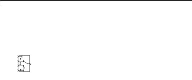
Multiport Switch
Purpose |
Choose between multiple block inputs |
Library |
Signal Routing |
Description |
Types of Block Inputs |
|
The Multiport Switch block chooses among several inputs. The first |
|
input is the control input, while the others are data inputs. The value of |
|
the control input determines which data input passes to the output port. |
|
|
|
Note This block is the same as the Index Vector block. If you set |
|
Number of data ports to 1, you get the Index Vector block. |
|
When you set Data port for default case to Additional data port, |
|
an extra data port with a * label appears below the other data inputs. |
|
For more information, see “How the Block Handles an Out-of-Range |
|
Control Input” on page 2-1020. |
|
Rules That Determine the Block Output |
|
You specify the number of data inputs with Number of data ports. |
|
Data inputs can be scalar or vector. |
|
• If you specify only one data input and that input is a vector, the block |
|
behaves as an index selector, and not as a multiport switch. The |
|
block output is the input vector element whose index matches the |
|
control input. |
|
• If you specify more than one data input, the block behaves as a |
|
multiport switch. The block output is the data input that corresponds |
|
to the value of the control input. If at least one of the data inputs is a |
|
vector, the block output is a vector. In this case, the block expands |
|
any scalar inputs to vectors. |
|
• If the data inputs are scalar, the output is a scalar. |
2-1018

Multiport Switch
How the Block Interprets the Control Input
The following table summarizes how the block interprets the control input and passes data to the output.
|
Control |
Truncation |
Setting for |
Block Behavior During Simulation |
|
|
|
Input |
|
Data Port |
|
|
|
|
|
The specified data |
And an out-of-range |
|
||
|
|
|
Order |
|
||
|
|
|
input passes to the |
error occurs when... |
|
|
|
|
|
|
|
||
|
|
|
|
output based on... |
|
|
|
Integer |
None |
Zero-based |
Zero-based indexing |
The control input is |
|
|
value |
|
contiguous |
|
less than 0 or greater |
|
|
|
|
|
|
than the number of data |
|
|
|
|
|
|
inputs minus one |
|
|
|
|
One-based |
One-based indexing |
The control input is |
|
|
|
|
contiguous |
|
less than 1 or greater |
|
|
|
|
|
|
than the number of data |
|
|
|
|
|
|
inputs |
|
|
|
|
Specify |
Indices you specify |
The control input does |
|
|
|
|
indices |
|
not correspond to any |
|
|
|
|
|
|
specified data port |
|
|
|
|
|
|
index |
|
|
Not an |
The block |
Zero-based |
Zero-based indexing |
The truncated control |
|
|
integer |
truncates |
contiguous |
|
input is less than 0 |
|
|
value |
the value to |
|
|
or greater than the |
|
|
|
an integer |
|
|
number of data inputs |
|
|
|
by rounding |
|
|
minus one |
|
|
|
to floor. |
|
|
|
|
|
|
One-based |
One-based indexing |
The truncated control |
|
|
|
|
|
contiguous |
|
input is less than 1 |
|
|
|
|
|
|
or greater than the |
|
|
|
|
|
|
number of data inputs |
|
|
|
|
Specify |
Indices you specify |
The truncated control |
|
|
|
|
indices |
|
input does not |
|
|
|
|
|
|
correspond to any |
|
|
|
|
|
|
|
|
2-1019

Multiport Switch
Control |
Truncation |
Setting for |
Block Behavior During Simulation |
|
Input |
|
Data Port |
|
|
|
The specified data |
And an out-of-range |
||
|
|
Order |
||
|
|
input passes to the |
error occurs when... |
|
|
|
|
||
|
|
|
output based on... |
|
|
|
|
|
|
|
|
|
|
specified data port |
|
|
|
|
index |
How the Block Handles an Out-of-Range Control Input
For a control input with an integer value, the input is out of range when the value does not match any data port indices. For a control input that is not an integer value, the input is out of range when the truncated value does not match any data port indices. In both cases, the block behavior depends on your settings for Data port for default case and Diagnostic for default case.
Behavior for Simulation
The following behavior applies only to simulation for your model.
2-1020
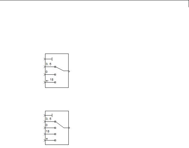
Multiport Switch
|
Data port for |
Diagnostic for default case |
|
|
|
|
default case |
|
|
|
|
|
None |
Warning |
Error |
|
|
|
|
|
|||
|
Last data |
Use the last |
Use the last |
Report an |
|
|
port |
data port and |
data port |
error and stop |
|
|
|
do not report |
and report a |
simulation. |
|
|
|
any warning or |
warning. |
|
|
|
|
error. |
|
|
|
|
|
|
|
|
|
|
Additional |
Use the |
Use the |
Report an |
|
|
data port |
additional data |
additional |
error and stop |
|
|
|
port with a |
data port |
simulation. |
|
|
|
* label and |
with a * label |
|
|
|
|
do not report |
and report a |
|
|
|
|
any warning or |
warning. |
|
|
|
|
error. |
|
|
|
|
|
|
|
|
|
Behavior for Code Generation
The following behavior applies to code generation for your model.
2-1021
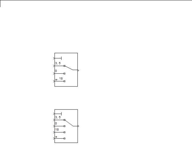
Multiport Switch
|
Data port for |
Diagnostic for default case |
|
|
|
|
default case |
|
|
|
|
|
None |
Warning |
Error |
|
|
|
|
|
|||
|
Last data |
Use the last |
Use the last |
Use the last |
|
|
port |
data port. |
data port. |
data port. |
|
|
|
|
|
|
|
|
Additional |
Use the |
Use the |
Use the |
|
|
data port |
additional data |
additional data |
additional data |
|
|
|
port with a * |
port with a * |
port with a * |
|
|
|
label. |
label. |
label. |
|
|
|
|
|
|
|
Guidelines on Setting Parameters for Enumerated Control Port
When the control port on the Multiport Switch block is of enumerated type, follow these guidelines:
2-1022
Multiport Switch
|
Scenario |
What to Do |
Rationale |
|
|
The |
• Set Data port order |
This block configuration |
|
|
enumerated |
to Specify indices. |
handles invalid values |
|
|
type contains |
• Set Data port indices |
that the enumerated type |
|
|
a value that |
explicitly represents. |
|
|
|
represents |
to use this value for |
|
|
|
the last data port. |
|
|
|
|
invalid, |
|
|
|
|
|
|
|
|
|
out-of-range, |
• Set Data port for |
|
|
|
or |
default case to Last |
|
|
|
uninitialized |
data port. |
|
|
|
values. |
|
|
|
|
The |
• Set Data port for |
This block configuration |
|
|
enumerated |
default case to |
handles invalid values |
|
|
type contains |
Additional data |
that the enumerated |
|
|
only valid |
port. |
type does not explicitly |
|
|
enumerated |
|
represent. |
|
|
values. |
|
|
|
|
However, a |
|
|
|
|
data input |
|
|
|
|
port can get |
|
|
|
|
invalid values |
|
|
|
|
of enumerated |
|
|
|
|
type. |
|
|
|
|
The |
• Set Data port for |
This block configuration |
|
|
enumerated |
default case to Last |
avoids unnecessary |
|
|
type contains |
data port. |
diagnostic action. |
|
|
only valid |
• Set Diagnostic for |
|
|
|
enumerated |
|
|
|
|
default case to None. |
|
|
|
|
values. Data |
|
|
|
|
|
|
|
|
|
input ports |
|
|
|
|
can never get |
|
|
|
|
invalid values |
|
|
|
2-1023

Multiport Switch
Data Type
Support
Scenario |
What to Do |
Rationale |
|
|
|
of enumerated |
|
|
type. |
|
|
The block does |
• Set Data port for |
This block configuration |
not have a |
default case to |
handles enumerated |
data input |
Additional data |
values that do not have |
port for every |
port. |
a data input port, along |
value of the |
|
with invalid values. |
enumerated |
|
|
type. |
|
|
The control signal can be of any data type that Simulink supports, including fixed-point and enumerated types. If the control signal is numeric, it cannot be complex. If the control signal is an enumerated signal, the block uses the value of the underlying integer to select a data port. If the underlying integer does not correspond to a data port, an error occurs.
The data signals can be of any data type that Simulink supports. If any data signal is of an enumerated type, all others must be of the same enumerated type.
For more information, see “Data Types Supported by Simulink” in the Simulink documentation.
2-1024
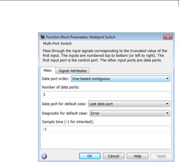
Multiport Switch
Parameters |
The Main pane of the Multiport Switch block dialog box appears as |
and |
follows: |
Dialog |
|
Box |
|
The Signal Attributes pane of the Multiport Switch block dialog box appears as follows:
2-1025
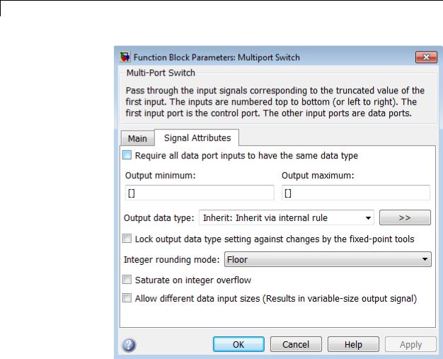
Multiport Switch
•“Data port order” on page 2-1028
•“Number of data ports” on page 2-1030
•“Data port indices” on page 2-1031
•“Data port for default case” on page 2-1033
•“Diagnostic for default case” on page 2-1034
2-1026

Multiport Switch
•“Sample time (-1 for inherited)” on page 2-1938
•“Require all data port inputs to have the same data type” on page 2-1036
•“Lock output data type setting against changes by the fixed-point tools” on page 2-1713
•“Integer rounding mode” on page 2-1714
•“Saturate on integer overflow” on page 2-1716
•“Allow different data input sizes” on page 2-1042
•“Output minimum” on page 2-1043
•“Output maximum” on page 2-1044
•“Output data type” on page 2-1045
•“Mode” on page 2-1047
•“Data type override” on page 2-1892
•“Signedness” on page 2-1050
•“Word length” on page 2-1051
•“Scaling” on page 2-1728
•“Fraction length” on page 2-1053
•“Slope” on page 2-1054
•“Bias” on page 2-1055
2-1027

Multiport Switch
Data port order
Specify the type of ordering for your data input ports.
Settings
Default: One-based contiguous (for Multiport Switch block), Zero-based contiguous (for Index Vector block)
Zero-based contiguous
Block uses zero-based indexing for ordering contiguous data ports.
One-based contiguous
Block uses one-based indexing for ordering contiguous data ports.
Specify indices
Block uses noncontiguous indexing for ordering data ports.
Tips
•When the control port is of enumerated type, select Specify indices.
•If you select Zero-based contiguous or One-based contiguous, verify that the control port is not of enumerated type. This configuration is deprecated and produces an error. You can run slupdate on your model to replace each Multiport Switch block of this configuration with a block that explicitly specifies data port indices.
•Avoid situations where the block contains unused data ports for simulation or code generation. When the control port is of fixed-point or built-in data type, verify that all data port indices are representable with that type. Otherwise, the following block behavior occurs:
|
If the block has unused data |
You get... |
|
|
ports and data port order |
|
|
|
is... |
|
|
|
Zero-based contiguous or |
A warning |
|
|
One-based contiguous |
|
|
|
Specify indices |
An error |
|
|
|
|
|
2-1028

Multiport Switch
Dependencies
Selecting Zero-based contiguous or One-based contiguous enables the Number of data ports parameter.
Selecting Specify indices enables the Data port indices parameter.
Command-Line Information
See “Block-Specific Parameters” on page 8-109 for the command-line information.
2-1029

Multiport Switch
Number of data ports
Specify the number of data input ports to the block.
Settings
Default: 3 (for Multiport Switch block), 1 (for Index Vector block)
The block icon changes to match the number of data input ports you specify.
Dependency
Selecting Zero-based contiguous or One-based contiguous for Data port order enables this parameter.
Command-Line Information
See “Block-Specific Parameters” on page 8-109 for the command-line information.
2-1030

Multiport Switch
Data port indices
Specify an array of indices for your data ports.
Settings
Default: {1,2,3}
The block icon changes to match the data port indices you specify.
Tips
•To specify an array of indices that correspond to all values of an enumerated type, enter enumeration('type_name') for this parameter. Do not include braces.
For example, enumeration('MyColors') is a valid entry.
•To enter specific values of an enumerated type, use the type_name.enumerated_name format. Do not enter the underlying integer value.
For example, {MyColors.Red, MyColors.Green, MyColors.Blue} is a valid entry.
•To indicate that more than one value maps to a data port, use brackets.
For example, the following entries are both valid:
-{MyColors.Red, MyColors.Green, [MyColors.Blue, MyColors.Yellow]}
-{[3,5],0,18}
•If the control port is of fixed-point or built-in data type, the values for Data port indices must be representable with that type. Otherwise, an error appears at compile time to alert you to unused data ports.
•If the control port is of enumerated data type, the values for Data port indices must be enumerated values of that type.
•If Data port indices contains values of enumerated type, the control port must be of that data type.
2-1031

Multiport Switch
Dependency
Selecting Specify indices for Data port order enables this parameter.
Command-Line Information
See “Block-Specific Parameters” on page 8-109 for the command-line information.
2-1032
Multiport Switch
Data port for default case
Specify whether to use the last data port for out-of-range inputs, or to use an additional port.
Settings
Default: Last data port
Last data port
Block uses the last data port for output when the control port value does not match any data port indices.
Additional data port
Block uses an additional data port for output when the control port value does not match any data port indices.
Tip
If you set this parameter to Additional data port and Number of data ports is 3, the number of input ports on the block is 5. The first input is the control port, the next three inputs are data ports, and the fifth input is the default port for out-of-range inputs.
Command-Line Information
See “Block-Specific Parameters” on page 8-109 for the command-line information.
2-1033

Multiport Switch
Diagnostic for default case
Specify the diagnostic action to take when the control port value does not match any data port indices.
Settings
Default: Error
None
Do not show any warning or error message.
Warning
Show a warning message in the MATLAB Command Window and continue the simulation.
Error
Show an error message in the Simulation Diagnostics Viewer and stop the simulation. In this case, the Data port for default case is used only for code generation and not simulation.
For more information, see “How the Block Handles an Out-of-Range Control Input” on page 2-1020.
Command-Line Information
See “Block-Specific Parameters” on page 8-109 for the command-line information.
2-1034

Multiport Switch
Sample time (-1 for inherited)
Enter the discrete interval between sample time hits or specify another appropriate sample time such as continuous or inherited.
Settings
Default: -1
By default, the block inherits its sample time based upon the context of the block within the model. To set a different sample time, enter a valid sample time based upon the table in “Types of Sample Time”.
See also “Specify Sample Time” in the online documentation for more information.
Command-Line Information
See “Block-Specific Parameters” on page 8-109 for the command-line information.
2-1035

Multiport Switch
Require all data port inputs to have the same data type
Specify allowed data types.
Settings
Default: Off
 On
On
Requires all data port inputs to have the same data type.
 Off
Off
Allows data port inputs to have different data types.
Command-Line Information
See “Block-Specific Parameters” on page 8-109 for the command-line information.
2-1036

Multiport Switch
Lock output data type setting against changes by the fixed-point tools
Select to lock the output data type setting of this block against changes by the Fixed-Point Tool and the Fixed-Point Advisor.
Settings
Default: Off
 On
On
Locks the output data type setting for this block.
 Off
Off
Allows the Fixed-Point Tool and the Fixed-Point Advisor to change the output data type setting for this block.
Command-Line Information
See “Block-Specific Parameters” on page 8-109 for the command-line information.
See Also
For more information, see “Use Lock Output Data Type Setting”.
2-1037

Multiport Switch
Integer rounding mode
Specify the rounding mode for fixed-point operations.
Settings
Default: Floor
Ceiling
Rounds both positive and negative numbers toward positive infinity. Equivalent to the MATLAB ceil function.
Convergent
Rounds number to the nearest representable value. If a tie occurs, rounds to the nearest even integer. Equivalent to the Fixed-Point Toolbox convergent function.
Floor
Rounds both positive and negative numbers toward negative infinity. Equivalent to the MATLAB floor function.
Nearest
Rounds number to the nearest representable value. If a tie occurs, rounds toward positive infinity. Equivalent to the Fixed-Point Toolbox nearest function.
Round
Rounds number to the nearest representable value. If a tie occurs, rounds positive numbers toward positive infinity and rounds negative numbers toward negative infinity. Equivalent to the Fixed-Point Toolbox round function.
Simplest
Automatically chooses between round toward floor and round toward zero to generate rounding code that is as efficient as possible.
Zero
Rounds number toward zero. Equivalent to the MATLAB fix function.
2-1038

Multiport Switch
Command-Line Information
See “Block-Specific Parameters” on page 8-109 for the command-line information.
See Also
For more information, see “Rounding” in the Simulink Fixed Point documentation.
2-1039

Multiport Switch
Saturate on integer overflow
Specify whether overflows saturate.
Settings
Default: Off
 On
On
Overflows saturate to either the minimum or maximum value that the data type can represent.
For example, an overflow associated with a signed 8-bit integer can saturate to -128 or 127.
 Off
Off
Overflows wrap to the appropriate value that is representable by the data type.
For example, the number 130 does not fit in a signed 8-bit integer and wraps to -126.
Tips
•Consider selecting this check box when your model has possible overflow and you want explicit saturation protection in the generated code.
•Consider clearing this check box when you want to optimize efficiency of your generated code.
Clearing this check box also helps you avoid overspecifying how a block handles out-of-range signals. For more information, see “Checking for Signal Range Errors”.
•When you select this check box, saturation applies to every internal operation on the block, not just the output or result.
•In general, the code generation process can detect when overflow is not possible. In this case, the code generator does not produce saturation code.
2-1040

Multiport Switch
Command-Line Information
See “Block-Specific Parameters” on page 8-109 for the command-line information.
2-1041