

Operating Manual for R-S Rheometer
.pdfInsert carefully the measuring bob into the measuring bob coupling. Pay attention to insert the measuring bob shaft into the measuring bob coupling without impact.
Move down the coupling sleeve of the measuring bob coupling (ring covered).
Fasten the measuring cup at the measuring cup mounting flange with the help of measuring cup thread.
By moving down the stand, immerse the measuring cup into the substance up to the ring mark or up to the point where diameter of measuring cup increases.
Fig. 7.: Depth of immersion
Pay attention to the fact that any substance or solvent does not ingress into measuring bob coupling, measuring drive or electronics.
Now the measurement can be carried out.
After the end of measurement unscrew the measuring cup thread and remove measuring cup. Then open the measuring bob coupling and remove the measuring bob.
Clean measuring cup and measuring bob carefully. Do not use hard objects, always prevent scratches!
Store measuring bobs on a soft pad. \
V.2 Measurement with substance in measuring system
Fill the measuring cup with substance (sample filling quantity see Appendix A1 “Data sheets of the standard measuring system”).
Avoid air bubbles when filling in the substance as they result in non-reproducibility of the measured values.
Place the measuring bob in measuring cup. Lift the coupling sleeve of the measuring bob coupling (ring visible). Insert the complete measuring system from below into the measuring cup mounting flange and screw tight using the measuring cup thread. Insert the measuring bob shaft into the measuring bob coupling without impact. Now insert the measuring bob shaft completely into the measuring bob coupling and move down the coupling sleeve of the measuring bob coupling (ring is covered).
In this case of measurement the substance temperature control can be carried out by immersing the measuring system into a thermostat (delivery as special accessory). It is necessary to pay attention to the immersion depth (Chapter 5.1).
Brookfield Engineering Labs., Inc. |
Page 21 |
M/02-212 |

Temperature range max.: 0°C ... +90°C.
The cooling device “KE” is required to expand the temperature range to -20°C ...+180°C
The temperature sensor Pt100 may be immersed in medium only at 2/3 of the metal rod length! Cable must be always outside the medium.
If you want to measure with temperature control, the thermostat must be pre-set at the desired temperature and you should wait till the necessary temperature of the substance is reached (e.g. temperature measurements through the Pt100 menue point “Utilities → Meas.-Temperature”, see Chapter 6).
Now the measurement can be carried out.
To remove the measuring system after the measurement first open the measuring bob coupling and then unscrew the measuring cup thread.
Attention: If you have carried out measurements at higher or very low temperatures please take care: Some accessible surfaces can become very hot or cold. Before removing measuring system please wait till the system-surface-temperature equalized to nearly room temperature and allows you to touch the system without danger.
When unscrewing the measuring cup, you must hold the measuring system tightly with one hand! Due to its own weight measuring system would fall downwards.
Clean measuring cup and measuring bob carefully, do not use hard objects, always prevent scratches! Store measuring bobs on a soft pad.
V.3 Measurement with temperature control device FTK-CC
In case of one-way measuring systems insert the one-way measuring cup into the measuring cup mounting.
Fill the measuring cup with substance (sample filling quantity see Appendix A1 “Data sheets of the standard measuring system”).
Avoid air bubbles when filling in the substance as they result in non-reproducibility of the measured values.
Place the measuring bob in measuring cup. Lift the coupling sleeve of the measuring bob coupling (ring visible). Insert the complete measuring system from below into the temperature control device and screw tight using the measuring cup screw. Insert the measuring bob shaft into the measuring bob coupling without impact. Now insert the measuring bob shaft completely into the measuring bob coupling and move down the coupling sleeve of the measuring bob coupling (ring is covered).
The thermostat must now be pre-set at the desired temperature and you should wait till the necessary temperature of the substance is reached (e.g. temperature measurements through the Pt100 menue point “Utilities → Meas.-Temperature”, see Chapter 6).
Now the measurement can be carried out.
Brookfield Engineering Labs., Inc. Page 22 M/02-212

To remove the measuring system after the measurement first open the measuring bob coupling and then unscrew the measuring cup screw of temperature control device.
Attention: If you have carried out measurements at higher or very low temperatures please take care: Some accessible surfaces can become very hot or cold. Before removing measuring system please wait till the system-surface-temperature equalized to nearly room temperature and allows you to touch the system without danger.
When unscrewing the measuring cup, you must hold the measuring system tightly with one hand! Due to its own weight measuring system would fall downwards.
In case of one-way measuring cups eject the one-way measuring cup with the measuring cup ejector.
Clean the measuring bob carefully, do not use hard objects, always prevent scratches! Store measuring bobs on a soft pad.
V.4 Measurement with cone/plate and plate/plate measuring systems
Insert and adjustment of the measuring cone or measuring plate
To install the measuring bob the bayonet lock must be released (position “opened”) and the lower measuring plate must be displaced down. Caution: during release of the bayonet lock the measuring device has to be hold tight at height adjustment ring.
Lift the coupling sleeve of the measuring bob coupling (ring visible). Insert the measuring bob (cone or plate) from below into measuring coupling. Move down the coupling sleeve of the measuring bob coupling (ring covered).
Loosen the inner hexagon screw at measuring bob shaft.
Press measuring plate upward again and close bayonet lock (position “closed”).
Loosen scale clamp screw at height adjustment ring.
0-/red-position

 0
0
0 |
Scale fixing screw |
|
Height adjustment ring
Turn left |
Turn right |
lower |
lift |
The upper marker (“0”) and the lower red marker (red mark) are brought into coincidence rotating the height adjustment ring (=0-/red position, see picture).
Brookfield Engineering Labs., Inc. |
Page 23 |
M/02-212 |
In order to avoid thread backlash, the height adjustment ring must be now obligatory turn through to “0.4” (turn to the right = lift) and then again return back to the 0/red position.
Now screw on the inner hexagon screw at measuring bob shaft finger-tight ; this fixes the measuring bob in this position.
After rotating the scale mark from 0-/red position to the 0/0 position the cone/plate measuring device is ready for measurements.
To protect lower plate against accidental turning please fasten scale fixing screw finger-tight .
Open the bayonet lock and lower the lower plate. Apply the desired measuring substance to the lower plate.
Lift up carefully the lower plate again and fix the bayonet lock.
Caution: Excess of medium at plate edge must be removed (error influence!)
The thermostat must now be pre-set at the desired temperature and you should wait till the necessary temperature of the substance is reached (e.g. temperature measurements through the Pt100 menue point “Utilities → Meas.-Temperature”, see Chapter 6).
Brookfield Engineering Labs., Inc. |
Page 24 |
M/02-212 |

VI. Operation and Menue System
In the following chapter you will get overview on operations, menue system of R/S Rheometer and measurements, both in manual and PC controlled modes.
The menue-system of R/S Rheometer (firmware-version 4.02) is a dual-language system. Following languages are software selectable:
•English
•German
Desired language can be selected via menue item Configuration→Language (if English language is active) or Konfiguration→Sprache (if German language is active).
More details on language selection see chapter 6.7.6.
The following chapter will describe instrument handling with ENGLISH language active.
After switching on the R/S Rheometer, LCD indicates the following information for few seconds:
*Name of the Rheometer;
*Software firmware-version installed in the instrument (Brand name);
*Serial number of the instrument (xxxxxx);
*Date and time;
Example: |
|
|
|
R/S Rheometer |
|||
|
|||
|
Ver.: 4.02 #xxxxxx |
||
|
07.05.98 |
15.12 |
|
|
© Brookfield |
|
|
After about 5 sec the instrument checks voltages of the Power Supply Unit. Displayed voltages are to lie in the range from 14.9 to 16 V. Otherwise, some technical fault has occurred (→ Repairs).
Beispiel: |
Voltage check: |
|
VCC:15.25 V |
|
|
This message is displayed for about 3 seconds. Then the MAIN menue is displayed.
Before you will get overview of the menue system of R/S Rheometer (Chapter 6.4), at this place it is worth to make a brief summary on the rheometer keyboard and corresponding rheometer functions.
Brookfield Engineering Labs., Inc. |
Page 25 |
M/02-212 |

VI.1 Keyboard
|
|
|
BROOKFIELD |
|
|
START/STOP |
- menue: previous menue-entry |
|
|
|
|
- back to parent menue |
|
- input: |
|
|
MAIN-menue |
|
|
- break |
|
- Run Single |
|
|
|||
increment value/letter |
|
- Run Program |
> |
|
- start of measurement |
|
|
|
- Remote |
|
- break of measurement |
||
|
|
|
|
|
|
|
- menue next menue entry |
|
|
R/S Rheometer |
|
|
|
|
|
|
|
|
|
|
- input: |
|
|
|
|
|
|
|
|
|
ST |
OK |
||
decrement value/letter |
|
|
|
|||
|
|
|
|
|
- enter |
|
|
|
|
OK |
|||
|
|
|
|
|||
|
|
|
|
- select |
||
|
|
|
|
|
|
|
|
- one digit to the left |
|
|
- one digit to the right |
||
All user inputs are made with help of 6 keys located below LCD-Display. Some of the keys are of multiple use, i.e. their function depends on actual executed operation. The following table shows detailed overview on keyboard functions.
Brookfield Engineering Labs., Inc. |
Page 26 |
M/02-212 |

Key-function dependent to executed operation
key |
operation |
Function of key |
example |
|
Menue |
goto previous menue-entry |
|
|
(above active one) |
|
Value-input |
increment |
|
Selection from List |
list entry above active |
|
|
entry (previous) |
|
Menue |
goto next menue-entry |
|
|
(below active one) |
|
Value-input |
decrement |
|
Selection from List |
list entry below active |
|
|
entry (next) |
|
Menue |
goto previous menue-entry |
|
|
(above active one) |
|
Value-input |
one digit to the right |
|
Selection from List |
list entry above active |
|
|
entry (previous) |
|
Menue |
goto next menue-entry |
|
|
(below active one) |
|
Input |
one digit to the left |
|
Selection from List |
list entry below active |
|
|
entry (next) |
ST |
Menue |
return to parent-menue |
|
||
|
Value-input |
Input break |
|
|
(only if possible) |
|
Selection from List |
Selection break |
|
|
(only if possible) |
|
Messung |
START and BREAK |
|
|
of measurement |
|
Remote active |
Break of measurement |
|
|
Back to MAIN-menue |
OK |
Menue |
execute Menue item |
|
||
|
|
(open sub-menue) |
|
Value-input |
End of input / enter value |
|
Selection from List |
select active item |
„Utilities“ → „Remote“
„8“ → „9“ „A“ → „B“
Select Meas.system „CC45“ → „CC48“
„Remote“ → „Utilities“
„5“ → „4“ „F“ → „G“
Select Meas.system „CC48“ → „CC45“
„Utilities“-> „Remote“
„100.00“->„100.00“ „Test“->„Test“ Select Meas.system „CC45“ -> „CC48“
„Remote“->Utilities“
„100.00“->„100.00“ „Test“->„Test“ Select Meas.system „CC45“ -> „CC48“
„UTILITY“->„MAIN“
Select Meas.system
->back to menue
break while measuring
Messung
A novice might perceive this keyboard layout excessively complicated, however, even after your first experiments, you will surely come to the conclusion, that you do not need the layout Table for reference and multi-function keys ensure major simplification of the operations.
Brookfield Engineering Labs., Inc. |
Page 27 |
M/02-212 |

VI.2 Menu System of R/S Rheometer
Main- |
|
Run Single |
Measurement at constant shear rate or shear |
Menue |
|
|
stress |
|
|
|
|
|
|
Run |
Measurement with pre-defined program |
|
|
Program |
|
|
|
|
|
|
|
Remote |
Measurement under PC control (remote control) |
|
|
|
|
Utilities |
Zero |
Zero-point calibration |
|
Calibration |
|
|
Edit |
Define/edit program |
|
Programs |
|
|
Print programs from memory |
|
|
Programs |
|
Measuring-
Systems
Memory
Clear
Memory
Measure
Temperature
Configuration Set
output-mode
Set meas- count-mode
Reset meascount
Set
Time/Date
Set RS232-
Parameter
Language
Service
Service2
Define / edit of measuring systems
Print measuring data from memory
Clear measuring data in memory
Permanent measuring of temperature
Selection of output mode for measuring data (via printer /
Selection of measuring counter mode
Reset measuring counter
Setting of time and date
Parameter input for serial communication port (RS232)
Language selection of userlanguage
Only for service personnel!
This page demonstrates organization of R/S Rheometer menue system.
Brookfield Engineering Labs., Inc. |
Page 28 |
M/02-212 |

Menu handling
Because LCD display of R/S Rheometer cannot show simultaneously all menue items, only part of the menue (three entries) is always displayed. Two arrows “>“ at the right side of display inform you, if there are still entries in the menue, either above (the arrow in the 2nd line), or below (the arrow in the 4th line).
Currently active (but still not selected) entry is marked by blinking black field (cursor) at the left part of LCD.
Example:
This entry is preselected and can be selected by pressing the “OK“-key
MAIN menue |
|
This menue contains |
- Run Single |
|
|
|
more items below. |
|
- Run Program |
|
|
- Remote |
> |
|
Using |
|
and |
|
|
keys you can move cursor upwards and downwards in the menue until desired |
menue item is reached. |
|
||||
Note: If there are more menue entries in the menue and you are reaching the end of the display, next part of menue is opened automatically (scrolling).
You can “start” the pre-set menue entry or open with OK |
key. |
The major menue (getting active ca. 10 seconds after switching on the instrument) is the MAIN menue.
In the case, you are in a submenue and wish to return to upper menue, press ST |
key. |
Example: |
|
|
|
CONFIGURATION-,emie |
|||
|
|||
|
- Set time/date |
> |
|
|
- Set RS232 Param. |
|
|
|
- Language |
|
|
Menu has more entries above.
Press |
ST |
,you return back to MAIN-menue. |
Main-menue
-Run Single
-Run Program
- Remote |
> |
If you push OK |
key now, the “Run Single“ function is started. |
Before we come to detailed description of this functions like “Run Single“ (see Chapter 6.5), it is worth to explain, how to input numbers and alphanumeric texts as well as select from a list, because majority of the Rheometer functions require such actions from the user before execution of a desired function.
VI.3 Selecting from Lists
If the Rheometer wants you to select an entry of a list, there are the same rules and functions of LCD and keyboard as in menue operations.
•Selection from a list is requested, for example at:
•Selection of a measuring system for measurements in “Run Single” or “Edit Program”;
•Selection of pre-set values for measurements in “Run Single” or “Edit Program”;
Brookfield Engineering Labs., Inc. |
Page 29 |
M/02-212 |
•Selection of a program or a measuring system you want to edit in “Edit Program” and “Meas. systems”;
•Answering a request “YES” ↔ “NO”.
•Selection of a program to start in “Run Program”
Keys |
|
|
and |
|
move cursor (= pre-selected entry) in the list upwards and downwards. |
|||
|
|
|
||||||
Key |
OK |
|
selects the pre-set entry from the list and |
ST |
key interrupts selection from the list (only if |
|||
possible). |
|
|
|
|
|
|||
As well as in the menue, an arrow in the right part of LCD display shows if there are still more elements of the list above or below the marked element.
Example for selection from a list: Selection of a measuring system.
Select Measuring system:
1)CC48>
2)DG
3)CC45 >
VI.4 Input of numerical values and alphanumeric texts
Majority of inputs, requested from user, are input of numbers. Pre-set values (e.g. start and end values of a slope), times, number of measurement points, factors, time, date, etc. are set as numbers with or without decimal digits.
If LCD display shows the decimal point “.” in a number to be entered, input of floating point number is requested.
However, number of digits after decimal point is fixed to number of displayed decimal digits, the decimal point cannot be moved.
Cursor (= the digit to be changed) is here a bar under the digit.
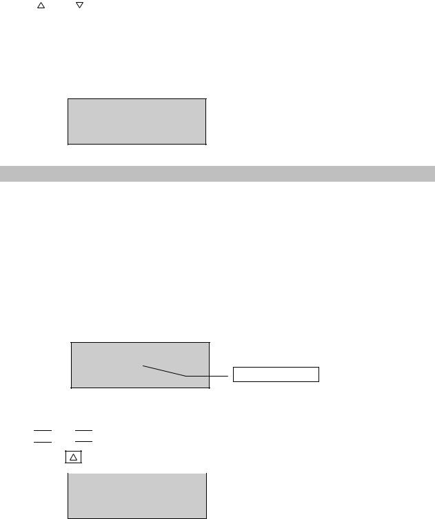
In the following example, the set value for Single Program measurement is to be adjusted by Digit Input. We want to enter the value 290.00 s-1 for Shear Rate.
Input Values:
Val.[1/s]:0100.00
Nr. of MP:010 Digit to be entered
Time[s]: 0100
The cursor is located under “1” in the value of shear rate to be set (currently 100.00 s-1).
Using

 and
and 

 keys one can change “1” (increment or decrement).
We push 1x |
and get: |
Input Values:
Val.[1/s]:0200.00
Nr. of MP:010
Time[s]:0100
Brookfield Engineering Labs., Inc. |
Page 30 |
M/02-212 |