

Operating Manual for R-S Rheometer
.pdfIII.2.2 AC-Adaptor
The AC adaptor supplies R/S Rheometer with power.
Only the AC-adaptor delivered by BROOKFIELD with your Rheometer may be used for power supply of R/S Rheometer.
The AC-adaptor may be inserted to the socket with corresponding grounding only. Connect the AC adaptor only using the plug in a proper way grounded to avoid electric shocks or damage of the system components. Pay attention also to “Requirements to the mains cable” (see Appendix).
Connecting the AC-adaptor:
-be sure that R/S Rheometer is switched off (mains switch “POWER” at the back side of the instrument);
-insert the instrument connector of the mains cable into AC adaptor;
-insert the plug of DC cable into the connector “DC” at the back side of R/S Rheometer;
-insert the mains plug of the mains cable into a grounded socket;
-turn on the R/S Rheometer again.
The AC-adaptor should not remain connected to the mains socket during long time with disconnected plug of the DC cable from the connector “DC” at the back side.
Before disconnecting R/S Rheometer from mains supply be sure that the Rheometer is switched off.
III.2.3 Printer Connection
Printer can be connected directly to the interface connector of the R/S Rheometer when measuring without PC support. You must preset “Printer” as output device to print the measuring values during measurement (see Chapter 6).
You should use obligatory a printer with parallel “CENTRONICS” interface.
-Turn off the R/S Rheometer with the mains switch “POWER” at the back side.
-Insert the printer connecting cable into the connector “CENTRONICS” at the back side of rheometer.
-Turn on R/S Rheometer again.
Standard printer cable (Printer ↔ PC) can be used as printer connecting cable. This cable is supplied with the printer in most cases.
To print data-values from R/S Rheometer all printers can be used which are printing text in ASCII-mode.
III.2.4 Computer Connection
If the R/S Rheometer has to be used in “REMOTE” mode with PC support (Rheo-program package) or with serial data-terminal for data logging it is necessary to connect the data link with the plug “RS232” at the instrument back side.
-Turn off the R/S Rheometer with the mains switch “POWER” at the back side.
-Turn off your computer system.
-Insert the data link into the plug “RS232” at the back side of the rheometer.
-Connect the other end of the data link with a free serial interface RS-232 (f.e. “COM2”) of your computer.
-Turn on the R/S Rheometer and your computer system again.
Use data link cable of BROOKFIELD delivery only!
Brookfield Engineering Labs., Inc. |
Page 11 |
M/02-212 |
Please read information concerning installation of the computer system in this Operation Manual.
III.3 Mounting of temperature controlled measuring devices
In this chapter you get information concerning mounting and attachment of the following accessories components:
•FTK-CC temperature control device for use of cylinder measuring system in the temperature range -10°C...+90°C (liquid’s temperature control)
•KE cooling device in conjunction with FTK-CC temperature control device or ME-CP/PP measuring device to rise the temperature range up to -20°C...+180°C
•ME-CP/PP measuring device for use of cone/plate and plate/plate measuring system in the temperature range -10°C...+90°C (liquid’s temperature control)
III.3.1 Mounting of temperature control device FTK-CC with and without cooling device KE
As temperature control device is available optionally: - FTK-CC
for use of cylinder measuring system in the temperature range -10°C...+90°C (liquid’s temperature control).
The temperature control device “FTK-CC” should be used only in the temperature range -10°C ...+90°C.
The cooling device “KE” is necessary additionally for temperature range of - 20°C...+180°C!
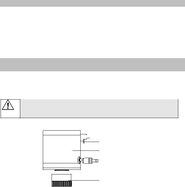
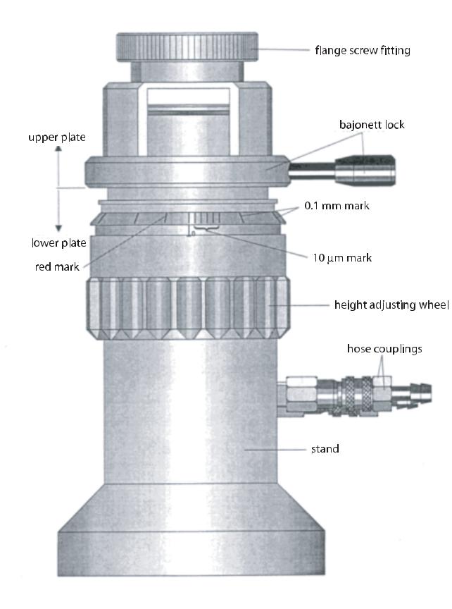
 thread joint for mounting flange


 hose connection of flow output
Pt 100
thermostating chamber
hose connection of flow input
measuring cup screw fitting
Fig.: 4.: Temperature control device FTK-CC
Mounting of the temperature control device “FTK-CC”
-Turn off the R/S Rheometer with the mains switch “POWER” at the instrument back side.
-When using cooling device KE mount cooling device first (see chapter 3.3.3)
-Set the “FTK-CC” from below on the mounting flange of R/S Rheometer and tighten the thread.
-Fix the hoses of liquid circulation thermostat at the “ FTK-CC ” as described below.
-Connect the FTK-CC´s built-in Pt100 cable with the connector “PT100” at the instrument back side of the R/S Rheometer.
Brookfield Engineering Labs., Inc. |
Page 12 |
M/02-212 |
BROOKFIELD
Main-Menue
-Run Single
-Run Program
-Remote
Power |
S T |
O K
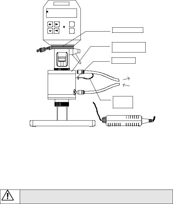
Cooling device KE
Temperature control device FTK-CC
Built in Pt100
Temperature control liquid from / to thermostatic device
Connecting cable Pt100
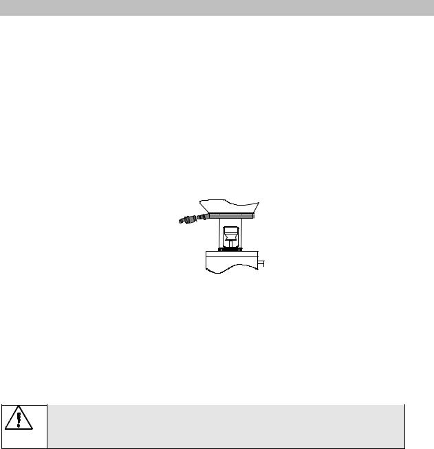
Fig. 5.: Operation with FTK-CC and cooling device KE
Thermostat connection to temperature control device FTK-CC
Hoses’ connections are necessary to join a liquid circulation thermostat by operation of the R/S Rheometer with liquid circulation temperature control device “FTK-CC”.
The hoses of liquid circulation thermostat are connected with the help of quick fitting couplings with the temperature control device “FTK-CC” (below: inlet; above: outlet). For this purpose it is necessary to move back the coupling’s bush, insert the hose and release the coupling. It fixes the hose (without screwing or rotation) by groove. Check by pulling gently whether the hoses’ connections are securely fixed.
The temperature control device “FTK-CC” without cooling device KE must only be used in the temperature range -10°C ...+90°C.
The temperature control device “FTK-CC” can be used in the temperature range -20°C...+180°C in case of using optionally obtainable cooling device “KE”.
It is recommended urgently to preset at liquid circulation thermostat the upper temperature limitation: when using water at 90°C and when using oil at 180°C (only with cooling device KE).
As thermostatic liquids are usually used:
|
-10 °C to +90 °C |
water (deionized) - glycol-mixture |
|
|
|
|
|
|
|
|
|
|
|
|
Brookfield Engineering Labs., Inc. |
Page 13 |
M/02-212 |
||
-20 °C to +250 °C |
thermostat oil |
|
|
Thermostatic fluids can be ordered from BROOKFIELD.
During measurements in the temperature range below -10°C and above +90°C the temperature control device “FTK-CC” may be put into operation only if the cooling liquid flows through the “KE” in order to prevent overheat of the measuring sensor.
III.3.2 Mounting of the measuring device ME-CP/PP
-Turn off the R/S Rheometer with the mains switch “POWER” at the instrument back side.
-When using cooling device KE mount cooling device first (see chapter 3.3.3)
-Set the “ME-CP/PP” from below on the mounting flange of measuring cup and tighten the thread. Check that before tightening the guide pin of the measuring device must be in the slot of the R/S Rheometer mounting flange!
-Fix the hoses of liquid circulation thermostat at the “ME-CP/PP” (see below).
-Insert the cable “VK-MB” supplied to the “ME-CP/PP” in the built-in Pt100 and in the connector “PT 100” at the instrument back side of the R/S Rheometer.
-For mounting the cone/plate or plate/plate measuring systems to measuring device refer to chapter 5.
Thermostat connection to temperature control device FTK-CC
Hoses’ connections are necessary to join a liquid circulation thermostat by operation of the R/S Rheometer with liquid circulation measuring device “ME-CP/PP”.
The hoses of liquid circulation thermostat are connected with the help of quick fitting couplings with the measuring device “ME-CP/PP” (below: inlet; above: outlet). For this purpose it is necessary to move back the coupling’s bush, insert the hose and release the coupling. It fixes the hose (without screwing or rotation) by groove. Check by pulling gently whether the hoses’ connections are securely fixed.
The measuring device “ME-CP/PP” without cooling device KE must only be used in the temperature range -10°C ...+90°C.
The measuring device “ME-CP/PP” can be used in the temperature range -20°C ... +180°C in case of using optionally obtainable cooling device “KE”.
It is recommended urgently to preset at liquid circulation thermostat the upper temperature limitation: when using water at 90°C and when using oil at 180°C (only with cooling device KE).
As thermostatic liquids are usually used:
-10 °C ... +90 °C |
Water (deionized) - glycol-mixture |
|
|
-20 °C ... +180 °C |
Thermostat oil |
|
|
The proper thermostatic liquids can be ordered from BROOKFIELD.
Brookfield Engineering Labs., Inc. |
Page 14 |
M/02-212 |
During measurements in the temperature range below -10°C and above +90°C the measuring device “ME-CP/PP” may be put into operation only if the cooling liquid flows through the “KE” in order to prevent overheat of the measuring sensor.
Brookfield Engineering Labs., Inc. |
Page 15 |
M/02-212 |
Measuring device for cone/plate and plate/plate measuring systems ME CC/CP
Brookfield Engineering Labs., Inc. |
Page 16 |
M/02-212 |
III.3.3 Mounting of the cooling device KE
The optionally supplied cooling device “KE” must be used in case of the R/S Rheometer operation with the liquid temperature control device “FTK-CC” or measuring device “ME-CP/PP“ in the temperature range below -10°C and above +90°C. When using cooling device KE temperature range of temperature control device “FTK-CC“ and measuring device “ME-CP/PP“ is expanded to -20°C... +180°C.
The cooling liquid flows through the cooling channel of the cooling device KE and prevents the heat transfer from the liquid’s temperated chamber of temperature control device “FTK-CC” or measuring device “ME-CP/PP“ to the R/S Rheometer.
Mounting
-Turn off the R/S Rheometer with the mains switch “POWER” at the instrument back side.
-Lift the “KE” from below to the R/S Rheometer and tighten the thread.
-Fix the hoses of the cooling loop at the “KE” (see below “Cooling water connection to cooling device KE”).
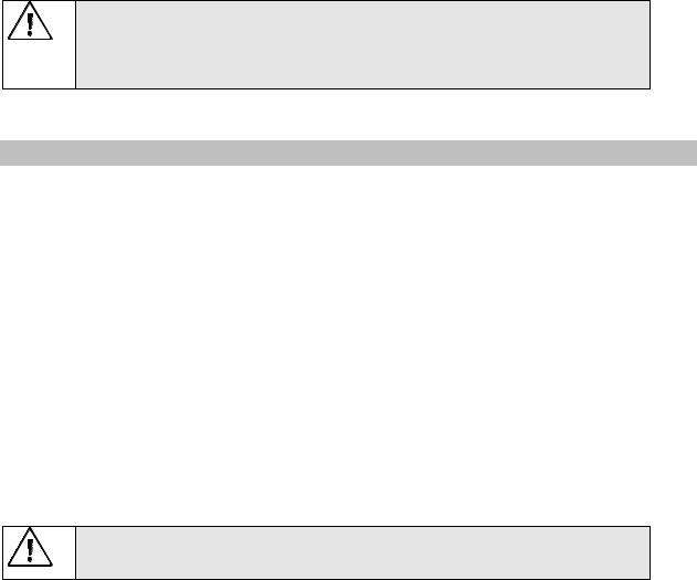
Fig. 6: cooling device KE
Cooling water connection to cooling device KE
The hoses of cooling circulation loop are connected with by quick fitting couplings the cooling device “KE”. For this purpose it is necessary to move back the coupling’s bush, insert the hose and release the coupling. It fixes the hose (without screwing or rotation) by groove. Check by easy pull if the hoses’ connections are firm.
During measurements in the temperature range below -10°C and above +90°C the “FTK-CC” / “MECP/PP“ may be put into operation only if the cooling liquid flows through the “KE” in order to prevent overheat of the measuring sensor.
Brookfield Engineering Labs., Inc. |
Page 17 |
M/02-212 |
IV. Environment, handling, cleaning and maintenance
In this chapter you get information concerning environment, handling, cleaning and maintenance of your R/S Rheometer.
IV.1 Operating environment, Storage
Find comfortable, convenient working place where you install your R/S Rheometer. It must be enough room for installation of the stand, measuring system, measuring substances and peripheral devices (for example printer, computer and thermostat).
You need a grounded socket for operation of the R/S Rheometer. You need also a socket for connection of the peripheral devices.
Your operating environment and the place for storage of the R/S Rheometer should not be extremely hot, extremely cold or moist.
Also avoid places where temperature and air humidity fluctuate strongly.
Moreover check that the R/S Rheometer is not subjected to
•dirt or dust,
•direct sun radiation,
•objects that emit strong heat (e.g. heating radiators),
•objects with strong electromagnetic field (e.g. loudspeakers, motors etc.),
•liquids or corrosive chemicals.
IV.2 Handling
The R/S Rheometer is designed in such way that even by easy kicks or vibrations its’ performance is failure-free. However, pay attention to absence of strong kicks or falls.
Never lift your R/S Rheometer at the measuring bob coupling or a built-in measuring bob and avoid everything that could influence free and concentric rotation of the measuring bob coupling (e.g. a shock).
If the measuring torque is exceeded, e.g. by shut-down of the measuring drive at full load or due to viscosity raise in solidification process, the safety device in electronic operates and prevents a failure. The R/S Rheometer could be under the load unlimited time also in such extreme cases.
IV.3 Cleaning
The paint of the R/S Rheometer resists attack by usual solvents and weak acids.
Use dry, clean, soft and nap-free cloth to clean the housing. Use neutral detergent liquids at a soft cloth in case of severe contamination of the housing.
Do not use any chemical products such as strong solvents or strong acids to clean the housing, especially the operating fields with the foil keyboard.
Brookfield Engineering Labs., Inc. |
Page 18 |
M/02-212 |
Check that any liquid does not penetrate into the housing (e.g. through the instrument connecting plugs) and into the bearings of the measuring drive. It results in the instrument damage!
IV.4 Maintenance
The R/S Rheometer is designed for long-term operation.
Nevertheless we recommend a regular maintenance in one-year cycle by a service engineer of BROOKFIELD or of corresponding representation.
Works on control electronics, all accessories, measuring drive as well as with the AC-adaptor and all electric circuits and connections may only be carried out by authorized service personnel trained by us.
Check of the measurements’ accuracy by the customer is possible any time. We recommend the measurement with the standard oils (normal oils).
Type: standard oil 2000 A, viscosity approx. 1.9 Pas
The measurement is carried out preferably with the temperature control device “FTK-CC” with measuring system CC25 DIN with Pt100 built-in in the bottom of the measuring cup.
The standard oil is thermostatted for at least 20 minutes at 20°C ± 0.05°C.
Select the appropriate measuring system.
Carry out measurements at the following preset values of shear rates:
10 s-1, 25 s-1, 50 s-1 and 100 s-1.
Print viscosities or read off viscosities from display.
In case of the instrument failure (or severe deviation from the preset value), please, apply to the service department of BROOKFIELD.
Brookfield Engineering Labs., Inc. |
Page 19 |
M/02-212 |

V. Measuring Systems
In this chapter you get information concerning use of the measuring system.
At present the following measuring system types are supplied:
a)Standard measuring systems MS-CC48...CC8 DIN/RC and DG-DIN/RC for measurement without temperature control device FTK-CC consists of:
-measuring cup for R/S Rheometer (MB-CC48...MB-CC8/RC and MB-DG/RC) depending on measuring-system
-measuring cup bottom
-measuring bob (MK-CC48...CC8/RC and MK-DG/RC) depending on measuring system
-thread protection
-
b)Standard measuring systems MS-CC48...CC8 DIN/FTK and DG-DIN/FTK for measurement with temperature control device FTK-CC consists of:
-measuring cup for R/S Rheometer (MB-CC48 ...CC8 DIN/FTK u. MB-DG DIN/FTK) depending on measuring system
-bottom screw
-measuring bobs (MK-CC48...CC8 DIN and MK-DG DIN) depending on measuring system
-optionally Pt100 temperature sensor in measuring cup bottom or in temperature control device
c)One-way measuring system EWS-CC48...CC8 DIN/FTK for measurement with temperature control device FTK-CC consists of:
-measuring cup mounting MBA-CC48...CC8 DIN/FTK depending on measuring system (holder for disposable one-way cups)
-one-way measuring cup (aluminum) EMB-CC48...CC8 DIN/FTK depending on measuring system
-measuring cup ejector
-measuring bob (MK-CC48...CC8 DIN)
d)Cone/plate measuring system C25-1...C50-2 for measurement with measuring device ME-CP/PP consists of:
-measuring cone (C25-1...C50-2) depending on measuring system
e)Plate/plate measuring system P25, P50 for measurement with measuring device SM-KP consists of:
-measuring plate (P25, P50) depending on measuring system
Please select a suitable measuring system for the desired measuring range to carry out measurements. (for details of measuring systems ranges refer to Appendix A)
V.1 Measurement directly in the substance
If necessary remove in case of measuring systems CC48...CC8-DIN the bottom from measuring cup and screw on the thread protection.
Attention when using DG-DIN!
When using the measuring system DG-DIN remove very carefully the O-ring seal between the measuring cup case and inner part. To do this open the measuring system below and take out the inner part. Take care not to damage or stretch the O-ring seal during removal! Insert the inner part again and screw the measuring system.
Lift the coupling sleeve of the measuring bob coupling (ring visible).
Brookfield Engineering Labs., Inc. |
Page 20 |
M/02-212 |