

8C - 18 OVERHEAD CONSOLE |
|
Ä |
|
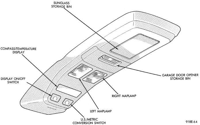
Fig. 2 Overhead Console
THERMOMETER AND COMPASS
The ignition switch must be in the ON or ACCESSORY position before the temperature and compass reading can be displayed. The COMP/TEMP switch turns the compass display on and off. The US/Metric switch changes the temperature reading from Fahrenheit to Celsius (Fig. 2).
When the vehicle is standing still, engine compartment temperatures may be radiated to the temperature sensor. Therefore the most accurate ambient temperature readings are displayed when the vehicle is moving in a forward motion.
When the ignition switch is in the ON position the temperature display is updated every 5 minutes. When the ignition switch is turned off the last displayed temperature reading stays in memory. When the ignition switch is turned on again the thermometer will display the memory temperature for 1 minute; then update the display to the actual temperature within 5 minutes.
COMPASS CALIBRATION
Do not attempt to set the compass near large metal objects, such as, other vehicles, large buildings, or bridges.
The compass unit automatically calibrates itself as the vehicle is driven; therefore, no calibration should be required. When the compass is first powered up,
the CAL light on the display should be on. The CAL light will go off and the compass will be accurate after the vehicle completes one to three complete circles.
If the vehicle's compass headings are inaccurate, the compass also can be manually calibrated using the following procedures:
(1)Depress and hold down both the Comp/Temp button and the U.S./Metric button.
(2)The display will go off and after 5 seconds the VAR light will come on. Continue to hold both buttons down.
(3)In approximately 10 seconds, the CAL light will come on. Release both buttons and the display will show the heading and outside temperature.
(4)Drive the vehicle 1 to 3 complete circles, without turning ignition OFF. The CAL light will then go off, showing the compass is calibrated.
If the compass portion of the display is not lit or compass readings are not accurate after calibration. The vehicle may have too much magnetism for the compass to be accurate or the compass circuitry is not working properly. Refer to Variance Procedure, Demagnetizing Procedure and/or Compass Diagnostics.
Ä
VARIANCE PROCEDURE
Variance is the difference between magnetic North and geographic North. In some areas the difference between magnetic and geographic North is great enough to cause the compass to give false readings. If this occurs, the variance must be set.
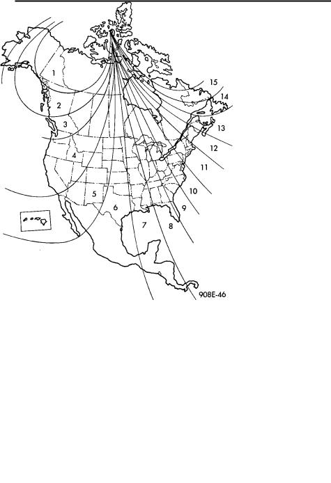
To set the variance, depress and hold down both the Comp/Temp button and the U.S./Metric button. The display will go off and after 5 seconds the VAR light will come on. Release both buttons. Using the zone map (Fig. 3) to find your geographic location, note the zone which you are in. Press the U.S./Metric button until the zone number appears on the display. Press the Comp/Temp button to enter your zone number.
Fig. 3 Variance Zone Map
Do not attach magnetic devices, such as magnetic CB antennas to the vehicle roof, as they can cause the compass to give false readings.
DEMAGNETIZING PROCEDURE
Every vehicle has its own magnetic field. This magnetic field is created by the various processes a steel roof goes through when the vehicle is built. A magnetic field also can be created if the roof is subjected to a magnet, example:
²Magnetic c.b. antenna
²Magnetic tipped screwdriver, etc.
OVERHEAD CONSOLE 8C - 19
If the roof becomes magnetized use a demagnetizing tool 6029 to demagnetize the roof.
In this demagnetizing procedure you will use the demagnetizing tool to demagnetize the roof and mounting screws in the overhead console. It is important that you follow the instructions below exactly. The mounting screws and the mounting brackets around the compass area are steel, and therefore aid in the demagnetizing of the roof panel.
(1)Be sure the ignition switch is in the OFF position before you begin the demagnetize procedure.
(2)Open the sun glass compartment to gain access to the overhead console mounting screws.
(3)Plug the demagnetizing tool into a standard 110/115 volt AC outlet, keeping the demagnetizing tool at least 12 inches away from the compass area when plugging it in.
(4)Slowly approach the console mounting screw with the plastic coated tip of the tool for at least 2 seconds.
(5)With the demagnetizing tool still energized, slowly back it away from the screw until the tip is at least 12 inches from the screw head.
(6)After you have pulled at least 12 inches from the last screw, remove the demagnetizer tool from inside of the vehicle and disconnect it from the electrical outlet.
(7)Place an 8 1/2 X 11 inch piece of paper lengthwise on the roof of vehicle directly above compass. The purpose of the paper is to protect the roof panel from scratches and define the area to be demagnetized.
(8)Plug in the demagnetizing tool, keeping it at least 2 feet away from the compass unit.
(9)Slowly approach the center of the roof panel at the windshield with the demagnetizing tool plugged in.
(10)Contact the roof panel with the tip of the tool and using slow sweeping motions of 1/2 inch between sweeps. Move the tool approximately 4 inches either side of the centerline and at least 11 inches back from the windshield.
(11)With the demagnetizing tool still energized, slowly back away from the roof panel until the tip is at least 2 feet from the roof before unplugging the tool.
(12)Recalibrate compass.
COMPASS DIAGNOSTICS
To place the unit into the diagnostics mode, turn the vehicle ignition off. Depress the Comp/Temp button while turning on the ignition/run switch. The display will then show DO. There are 3 tests that can be performed when in the diagnostics mode. Press the U.S./Metric button to choose test desired. Refer to Fig. 4 and 5.
Test 1 (d1) determines the magnetic field strength at the compass. The compass displays compensation
8C - 20 OVERHEAD CONSOLE |
|
Ä |
|
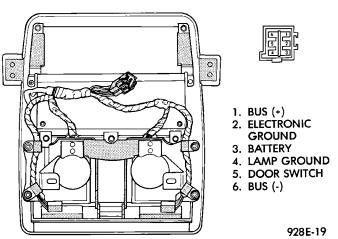
Fig. 4 Terminal Identification
numbers which, correspond to the current magnetic field strength at the compass. The letter N is displayed in the compass portion of the display. While a number which, corresponds to the magnetic field strength in the North/South direction is displayed. The temperature portion of the display or the letter
W is displayed in the compass portion of the display. A number which, corresponds to the magnetic field strength in the East/West direction is displayed in the temperature portion of the display. For proper compass operation the numbers should be between 1 and 14. A number of 7 or 8 is ideal (no vehicle magnetism) while numbers approaching 1 or 14 show that the vehicle is highly magnetic. If the numbers show that the vehicle is highly magnetic, perform the demagnetized procedure in this Group and retest for magnetism at compass. If the numbers show that the vehicle is highly magnetic, perform the demagnetizing procedure in this section and retest for magnetism at compass. The compass is not on the CCD bus, if not functioning properly, refer to the Overhead Console and Thermometer diagnosis.
Test 2 (d2) checks the electronic circuits of the compass, temperature, and CCD bus. If the test passes d2 will be displayed, and if the test fails F2 will be displayed. Refer to AG and AJ Body Diagnostic Procedure Manual for further testing procedures.
Test 3 (d3) performs a walking segment test which, sequentially puts different directions and numbers on the display. If any segment fails, replace the compass module.
Ä |
|
OVERHEAD CONSOLE 8C - 21 |
|
Fig. 5 Compass and Thermometer Diagnosis