

8C - 2 OVERHEAD CONSOLE |
|
Ä |
|
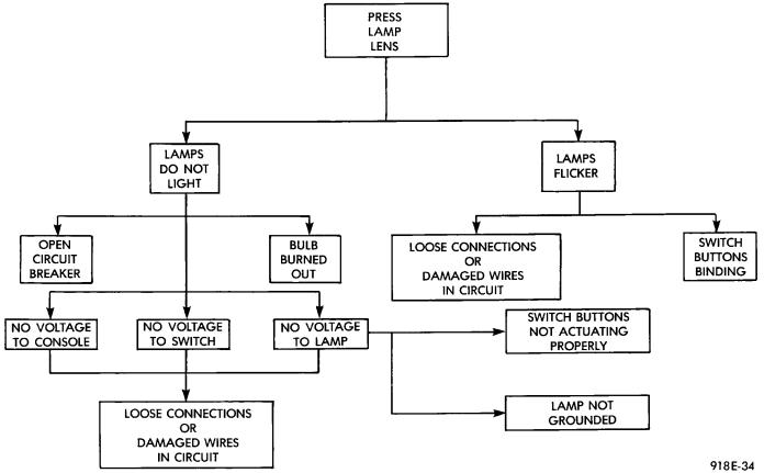
Fig. 2 Map Lamp Diagnosis
nected to a thermistor sensor which, located on the front lower radiator closure panel.
When the vehicle is standing still, engine compartment temperature may be radiated to the temperature sensor. Therefore the most accurate ambient temperature readings are displayed when the vehicle is moving in a forward motion.
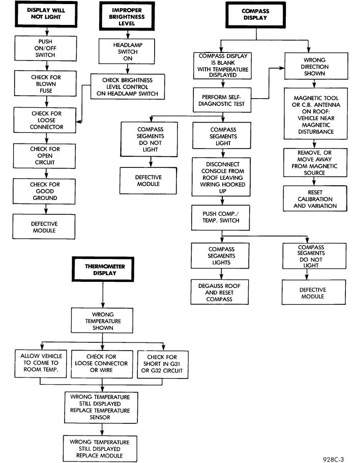
When the ignition switch is turned off the last displayed temperature reading stays in memory. When the ignition switch is turned on again the thermometer will display the memory temperature for 1 minute; then update the display to the actual temperature within 5 minutes. Refer to Compass and Thermometer Diagnosis (Fig. 3).
COMPASS CALIBRATION PROCEDURE
Do not attempt to set compass near large metal objects such as other vehicles, large buildings or, bridges and, remove all magnetic devices from roof panel. This compass is equipped with an auto-cali- bration feature which, eliminates the need to manually set compass calibration. For a short time, when the vehicle is new, the compass may appear erratic and the CAL symbol will be lit. After completing three complete 360 degree turns, in an area free of metal objects and on level ground, the CAL symbol will turn off and the compass will perform normally.
If at any time the compass should become inaccurate it can be put in auto-calibration mode by using the following procedure.
(1)Turn key to the ON position.
(2)Turn display off by pressing COMP/TEMP but-
ton.
(3)While continuing to hold COMP/TEMP button, depress and hold US/METRIC button for approximately 10 seconds, after 5 seconds the VAR symbol will light.
(4)The CAL symbol will light then the display will reappear. After completing three complete 360 degree turns, in an area free of metal objects and in no less than 48 seconds, the compass will be calibrated.
(5)Reset compass variation.
VARIANCE
Variance is the difference between magnetic North and geographic North. In some areas the difference between magnetic and geographic north is great enough to cause the compass to give false readings. If this occurs, the variance must be set.
VARIANCE SETTING PROCEDURE
To set the variance: Turn key on, and turn the display off by pressing the COMP/TEMP button. While
Ä |
|
OVERHEAD CONSOLE 8C - 3 |
|
Fig. 3 Compass and Thermometer Diagnosis