


8C - 8 OVERHEAD CONSOLE
If this message is displayed while the vehicle is at cruising speeds, immediate attention is required. If this message appears at idle speed, increase the idle speed and the message should go off. If the message remains on, immediate attention is required.
ENGINE TEMP CRITICAL
This message appears when a sensor has determined that the engine coolant is overheating. If this message comes on and stays on, immediate action is required.
COOLANT LEVEL LOW LOW FUEL LEVEL LOW BRAKE FLUID WASHER FLUID LOW
These messages will appear if a continuous warning condition is detected while the engine is running. Inspection is required. To clear this message from the display, after the condition is corrected, the ignition switch must be turned OFF.
CHECK TRANS
This message will appear if a continuous warning condition is detected while the engine is running. Immediate attention is recommended. To clear this message from the display, after the condition has been corrected, the ignition switch must be turned OFF.
VOLTAGE IMPROPER
This message will appear if a continuous warning condition is detected. Immediate attention is required. To clear this message from the display, after the condition has been corrected, the ignition switch must be turned OFF.
TURN SIGNAL ON
This message will appear if the turn signal is left on while vehicle speed is over 15 mph and the vehicle has traveled over one-half mile.
FASTEN SEAT BELTS
An intermittent chime tone will sound for several seconds if the seat belt is not fastened.
CHK ENGINE OIL LEVEL
If this message is delivered, a check of the engine oil dipstick is suggested. To clear this message, after the condition is corrected, the ignition switch must be turned OFF.
HEADLAMP OUT
BRAKE LAMP OUT TAIL LAMP OUT
These conditions are monitored only when the lamps are on. The message will remain, even after the lamp is replaced, until the lamp is turned on and operates.
SERVICE REMINDER
The maintenance reminder statement is programmed to provide general information only. Refer to Group 0, Lubrication & Maintenance for specific vehicle requirements.
The service reminder message is displayed at 7,500 miles or 12 months intervals, which ever comes first.
Ä
MONITORED SYSTEMS OK
If there is no warning condition to report, the message Monitored Systems OK is displayed (Fig. 2).
AUTOMATIC CALIBRATION SET PROCEDURE
The engine node will continuously and automatically recalibrate the compass under normal driving conditions. As long as the vehicle is turning, the engine node will record new compass data. This new data will be used to recalibrate the compass at a rate of at least once per full (360 degree) turn of the vehicle. Automatic calibration does not require operator interface.
MANUAL CALIBRATION SET PROCEDURE
Manual compass calibration has been replaced by automatic calibration set procedure. The manual calibration set procedure is available, but no longer serves any useful purpose.
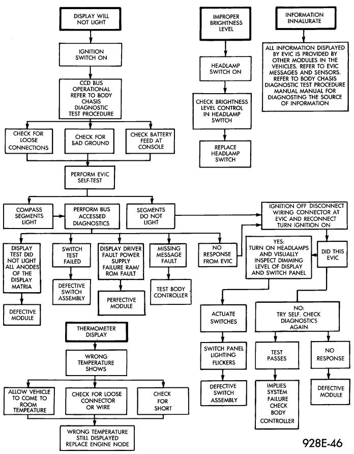
EVIC SELF CHECK DIAGNOSTICS
Ignition switch ON, the EVIC not displaying any massage, may imply a system failure and not an EVIC failure. Pressing the TEMP, FUEL and INFO buttons at the same time shall provide the visual message MODULE SELF CHECK for two seconds. Following at two second interval there will be massages:
²E2-0 SELF CHECK
²E3-0 SELF CHECK
²END OF SELF CHECK
Showing the microcomputer is working properly. When the self check mode and message shows:
²E2-1
²E3-2
This would show a fault exists in the EVIC's microcomputer and the EVIC should be replaced (Fig. 3).
BUS ACCESSED DIAGNOSTICS
The following diagnostic test may be used to check the integrity of the EVIC's internal connections and operations. Refer to the Body Chassis Diagnostic Test Procedure Manual for test procedures.
MODULE RESET TEST, when the EVIC receives this request from the DRB II, the EVIC will immediately enter into reset.
DISPLAY TEST: The EVIC receives a request from the DBR II, the EVIC will enter into a visual display mode. Also checks the integrity of the display driver to anode connections. The test shall consist of walking through the vertical and horizontal rows of anodes in the dot matrix display.
SWITCH STATUS TEST, when the EVIC receives this request from the DRB II, the EVIC will report the open/closed status of each individual switch.
Ä |
|
OVERHEAD CONSOLE 8C - 9 |
|
Fig. 3 Compass and Thermometer Diagnosis
8C - 10 OVERHEAD CONSOLE |
|
Ä |
|
FAULT BYTE TEST, when the EVIC receives this request from the DRB II, the EVIC will report fault status. Messages reported are:
²NO FAULT
²DISPLAY DRIVER FAULT
²EVIC MISSING MESSAGES
²POWER SUPPLY FAILURE
²FAULT IN RAM
²FAULT IN ROM
EVIC missing message implies that there may be a system failure and/or the body controller is not providing EVIC with sufficient information.
DISPLAY DRIVER FAULT, power supply failure and fault in RAM/ROM implies that the EVIC is defective.
CONSOLE REMOVAL
(1) Remove lenses (Fig. 4).
Fig. 5 EVIC Overhead Console
(3)Remove switch assembly by pulling down mounting tabs and swing assembly out of position.
(4)Disconnect switch wiring connector and remove electronic board and switch assembly. Replace function button switch assembly. The buttons are not serviceable.
(5)For installation reverse above procedures.
WIRING HARNESS REMOVAL
(1) Remove console, refer to Console Replacement (Fig. 6).
Fig. 4 EVIC Overhead Console Lens Removal
(2)Remove screws from visor tip-pin retainers.
(3)Remove screws in lens openings, after removing lamps.
(4)Remove console and disconnect wires.
(5)For installation reverse above procedures.
ELECTRONIC BOARD ASSEMBLY REPLACEMENT
(1)Remove console, refer to Console Replacement (Fig. 5).
(2)Remove six mounting screws holding bezel to housing.
(3)Remove switch assembly by pulling down mounting tabs and swing assembly out of position.
(4)Disconnect switch wiring connector and replace electronic board assembly.
(5)For installation reverse above procedures.
BEZEL/BUTTON SWITCH REMOVAL
(1)Remove console, refer to Console Replacement.
(2)Remove six mounting screws holding bezel to housing.
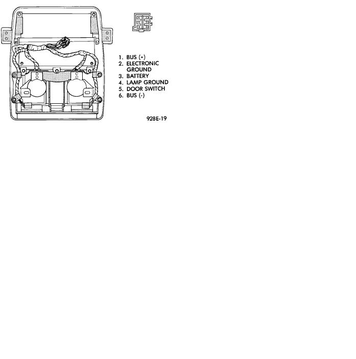
Fig. 6 EVIC Overhead Console Connector
(2)Disconnect wiring connector from retaining bracket.
(3)Remove screws, securing wiring to console housing.
(4)Remove push/slide switches. The reading lamp switch buttons are not serviceable.
(5)Remove lamp sockets from reflector bracket.
(6)Remove wiring.
(7)For installation reverse above procedures.
Ä
MAP READING LAMPS/POWER SUNROOF SWITCH REMOVAL
SWITCH REPLACEMENT
(1)Remove console, refer to Console Replacement.
(2)Disconnect switch wiring connector from retaining bracket.
(3)Pry switch out of bezel snap tabs.
(4)Replace switch.
(5)For installation reverse above procedures.
POWER SUNROOF SWITCH/BEZEL REMOVAL
(1)Remove console, refer to Overhead Reading/ Courtesy Lamp Console Replacement.
(2)Disconnect switch wiring connector from retaining bracket.
(3)Pry switch out of bezel. Replace switch. If necessary, push carefully at top closest to roof of bezel to disengage trim bezel and pivot bezel out of housing.
(4)Replace switch.
(5)For installation reverse above procedures.
LAMP/LENS REMOVAL
(1)Remove lens by inserting a flat blade tool between the round end of lamp lens and housing. Pry lens from the housing. Pivot the lens and remove (Fig. 4).
(2)Replace lamp as necessary.
(3)Position lens into housing by locating lens pivot and snap into place.
OVERHEAD READING/COURTESY LAMP CONSOLE
The two reading/courtesy lamps are actuated by pressing on the switch (Fig. 7):
OVERHEAD CONSOLE 8C - 11
²Courtesy lamps for when a door is opened
²Illuminated entry system is activated
²Headlamp switch is turned fully clockwise The map lamp console also includes:
²A cubby storage bin.
²Power sunroof switch, if equipped.
READING/COURTESY LAMP CONSOLE REMOVAL
(1)Remove screws from visor tip-pin retainers.
(2)Slide console forward until free from retainer bracket.
(3)Disconnect wiring.
(4)For installation reverse above procedures. For vehicles equipped with sunroof, avoid sliding console to install. Install screws for console attachment and push at rear of unit to snap over mounting bracket for engagement.
LAMP/LENS REMOVAL
(1)Remove lens by inserting a flat blade tool into slot located on the left side of lens. Pry lens to the side and swing down as it unhooks from housing (Fig. 4).
(2)Replace lamp as necessary.
(3)Position lens with the center tabs on the left side of lens snap into place. The lens are identified with L and R on the reverse side. Do not reverse the lens or it may damage the lens tabs.
OVERHEAD CONSOLE WIRING HARNESS REMOVAL
(1)Remove console, refer to Overhead Reading/ Courtesy Lamp Console Removal.
(2)Disconnect wiring connector from retaining bracket.
(3)Remove four screws attaching lamp housing to console bezel.
(4)Remove wiring and lamp housing.
(5)Remove lamp and replace assembly.
(6)For installation, reverse above procedures.
Fig. 7 Reading/Courtesy Lamp Console