


7-8 ENGINE LUBRICATION SYSTEM
Engine Oil and Oil Filter
 WARNING
Motorcycle operation with insufficient, deteriorated, or contaminated engine oil will cause accelerated wear and may result in engine or transmission seizure, accident, and injury.
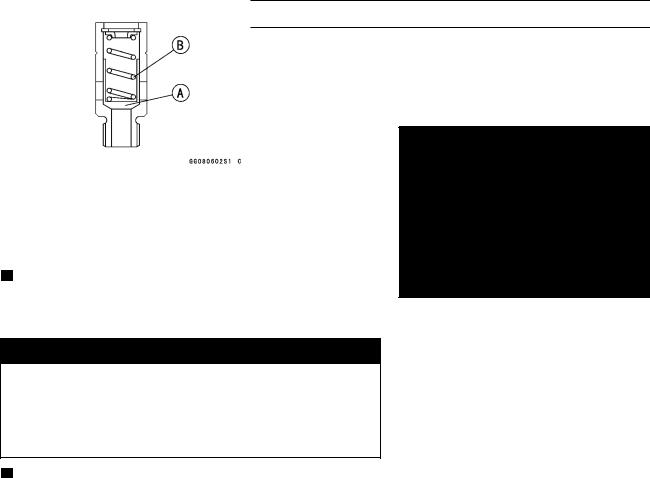
Oil• Level Inspection
Check that the engine oil level is between the upper [A] and lower [B] levels in the gauge.
NOTE
○Situate the motorcycle so that it is perpendicular to the ground.
○If the motorcycle has just been used, wait several minutes for all the oil to drain down.
○If the oil has just been changed, start the engine and run it for several minutes at idle speed. This fills the oil filter with oil. Stop the engine, then wait several minutes until the oil settles.
CAUTION
Racing the engine before the oil reaches every part can cause engine seizure.
If the engine oil gets extremely low or if the oil pump or oil passages clog up or otherwise do not function properly, the oil pressure warning light will light. If this light stays on when the engine is running above idle speed, stop the engine immediately and find the cause.
Engine• Oil Change
Refer to the Engine Lubrication System in the Periodic Maintenance chapter.
Oil• Filter Replacement
Refer to the Engine Lubrication System in the Periodic Maintenance chapter.

ENGINE LUBRICATION SYSTEM 7-9
Oil Pan
Oil• Pan Removal
Remove:
Engine Oil (drain, see Engine Lubrication System in the
Periodic Maintenance chapter)
Exhaust Pipe Assy and Muffler Body (see Engine Top
End chapter)
Oil Pan Bolts [A]
Oil Pan [B]
Oil• Pan Installation
•Clean the oil screen [A].
Install the oil screen so that the crankcase rib [B] fits the
•slot [C] of the oil screen.
Apply engine oil to the O-rings on the oil pipe.
If the oil pressure relief valve was removed, install it. ○Apply a non-permanent locking agent to the threads of
the oil pressure relief valve, and tighten it.
CAUTION
Do not apply too much non-permanent locking agent to the threads. This may block the oil passage.
Torque - Oil Pressure Relief Valve: 15 N·m (1.5 kgf·m, 11 ft·lb)
•Install the clamp [A] at an angle of within 45° [B] as shown.
•Replace the oil pan gasket with a new one.
•Tighten:
Torque - Oil Pan Bolts [C]: 11 N·m (1.1 kgf·m, 95 in·lb)
7-10 ENGINE LUBRICATION SYSTEM
Oil Pressure Relief Valve
Oil• Pressure Relief Valve Removal
See Oil Pan Removal.
Oil• Pressure Relief Valve Installation
See Oil Pan Installation.
Oil• Pressure Relief Valve Inspection
Check to see if the valve [A] slides smoothly when pushing it in with a wooden or other soft rod, and see if it comes back to its seat by spring [B] pressure.
NOTE
○Inspect the valve in its assembled state. Disassembly and assembly may change the valve performance.
If any rough spots are found during above inspection, wash the valve clean with a high-flash point solvent and blow out any foreign particles that may be in the valve with compressed air.

 WARNING
Clean the oil pressure relief valve in a well -ventilated area, and take care that there is no spark or flame anywhere near the working area. Because of the danger of highly flammable liquids, do not use gasoline or low-flash point solvent.
If cleaning does not solve the problem, replace the oil pressure relief valve as an assembly. The oil pressure relief valve is precision made with no allowance for replacement of individual parts.
ENGINE LUBRICATION SYSTEM 7-11
Oil Pump
Oil• Pump Removal
Drain:
Coolant (see Cooling System in the Periodic Maintenance chapter)
Engine Oil (see Engine Lubrication System in the Peri-
• odic Maintenance chapter) Remove:
Water Pipe Bolts [A]
Water Pipes [B]
•Remove:
Water Pump Cover Bolts [A]
Clamp [B]
Water Pump Cover [C]
•Remove:Impeller Bolt [A]
Washer
Impeller [B]
Water Pump Body
Oil Pump Cover
Oil (Water) Pump Shaft
Outer Rotor and Inner Rotor
Oil• Pump Installation
•Install the outer rotor [A] into the crankcase.
Install the pin [B], inner rotor [C] and oil (water) pump shaft [D].
○Turn the pump shaft so that the slot [E] in its shaft fits onto the projection [F] of the pump drive gear shaft.
•Fit the pin [A] of the oil pump cover [B] into the hole [C] in the crankcase.

7-12 ENGINE LUBRICATION SYSTEM
Oil Pump
•Install:Pins [A]
Water Pump Body [B]
•Install:
• Impeller [A], Washer and Bolt [B]
Tighten:
Torque - Water Pump Impeller Bolt: 9.8 N·m (1.0 kgf·m, 87
• in·lb)
Install: Pins [C]
Water Pump Cover and Bolts
Torque - Water Pump Cover Bolts: 11 N·m (1.1 kgf·m, 95 in·lb)
•Install:
• Water Pipes [A] Tighten:
Torque - Water Pipe Bolts [B]: 11 N·m (1.1 kgf·m, 95 in·lb)
Oil• Pump Drive Gear Removal
Remove:
Clutch (see Clutch chapter)
Oil Pan (see Oil Pan Removal)
Circlip [A] and Washer
Oil Pump Drive Gear
Oil• Pump Drive Gear Installation
Apply molybdenum disulfide oil solution to the journal por-
•tions [A] on the oil pump gear shaft [B]. Install:
• Washers [C]
Install the new circlip [D] into the groove of the oil pump drive gear shaft.