


10-10 WHEELS/TIRES
Wheels (Rims)
Axle Inspection |
|
•Remove the front and rear axles. |
|
•Visually inspect the front and rear axle for damages. |
|
If the axle is damaged or bent, replace it. |
|
•Place the axle in V blocks that are 100 mm (3.94 in.) [A] |
|
apart, and set a dial gauge [B] on the axle at a point |
|
halfway between the blocks. Turn [C] the axle to mea- |
|
sure the runout. The difference between the highest and |
|
lowest dial readings is the amount of runout. |
|
If axle runout exceeds the service limit, replace the axle. |
|
Axle Runout/100 mm (3.94 in.) |
|
Standard: |
TIR 0.05 mm (0.0020 in.) or less |
Service Limit: TIR 0.2 mm (0.008 in.)
Balance• Inspection
•Remove the wheel.
•Support the wheel so that it can be spun freely.
Spin the wheel lightly, and mark [A] the wheel at the top when the wheel stops.
○Repeat this procedure several times. If the wheel stops of its own accord in various positions, it is well balanced. If the wheel always stops in one position, adjust the wheel balance.
Balance• Adjustment
If the wheel always stops in one position, provisionally attach a balance weight [A] on the rim at the marking using
•adhesive tape.
Rotate the wheel 1/4 turn [B], and see whether or not the wheel stops in this position. If it does, the correct balance weight is being used.
If the wheel rotates and the weight goes up, replace the weight with the next heavier size. If the wheel rotates and the weight goes down, replace the weight with the next lighter size. Repeat these steps until the wheel remains
•at rest after being rotated 1/4 turn.
Rotate the wheel another 1/4 turn and then another 1/4 turn to see if the wheel is correctly balanced.
•Repeat the entire procedure as many times as necessary
•to achieve correct wheel balance. Permanently install the balance weight.
Balance• Weight Removal
Insert a standard screwdrivers [A] [B] between the rib [C]
•and the weight [D] as shown.
Pry the weight with two screwdrivers and remove the balance weight.
WHEELS/TIRES 10-11
Wheels (Rims)
CAUTION
When removing the balance weight, do not touch the brake disc. The disc could be damaged.
Do not tap the screwdrivers. The rim could be damaged.
Balance• Weight Installation
Check if the weight portion has any play on the clip.
If it does, discard it. WARNING
If the balance weight has any play on the rim, the clip of the weight have been stretched. Replace the loose balance weight.
Do not reuse used balance weight.
Unbalanced wheels can create an unsafe riding condition.
Balance Weight |
|
|
|
|
|
|
|
|
|
|
Part Number |
|
Weight |
|
|
41075–0007 |
10 |
g (0.35 |
oz.) |
|
41075–0008 |
20 |
g (0.71 |
oz.) |
|
41075–0009 |
30 |
g (1.06 |
oz.) |
NOTE
○Balance weights are available from Kawasaki dealers in 10, 20, and 30 grams (0.35, 0.71, and 1.06 oz.) sizes. An imbalance of less than 10 grams (0.35 oz.) will not usually affect running stability.
○Do not use four or more balance weight (more than 90 gram, 3.17 oz.). If the wheel requires an excess balance weight, disassemble the wheel to find the cause.
•Slip the balance weight [A] onto the rib [B] by pushing or lightly hammering [C] the clip [D].
Left Side [E] Right Side [F]
CAUTION
When installing the balance weight, do not touch the brake disc. The disc could be damaged.
•Check that the weight [A] and clip [B] are fully seated on the rim [C] and that the clip is hooked over the rib [D]. Left Side [E]
Right Side [F]
 WARNING
If the balance weight has any play on the rim, the clip of the weight has been stretched. Replace the loose balance weight.
Do not reuse balance weight.
Unbalanced wheels can create an unsafe riding condition.

10-12 WHEELS/TIRES
Tires
Air• Pressure Inspection
Refer to the Air Pressure Inspection in the Periodic Maintenance chapter.
Tire• Inspection
Refer to the Tire Wear Inspection in the Periodic Maintenance chapter.
Tire• Removal
Remove:
Wheel (see Front Wheel Removal, Rear Wheel Removal)
Disc(s)
• Valve Core (let out the air)
To maintain wheel balance, mark the valve stem position on the tire with chalk so that the tire can be reinstalled in the same position.
Chalk Mark or Yellow Mark [A]
Air Valve [B]
Align [C]
•Lubricate the tire beads and rim flanges on both sides with a soap and water solution or rubber lubricant. This helps the tire beads slip off the rim flanges.
CAUTION
Never lubricate with engine oil or petroleum distillates because they will deteriorate the tire.
•Remove the tire from the rim using a suitable commercially available tire changer.
NOTE
○The tires cannot be removed with hand tools because they fit the rims too tightly.
Tire Installation

 WARNING
•Inspect the rim and tire, and replace them if necessary.
•Clean the sealing surfaces of the rim and tire, and smooth the sealing surfaces of the rim with a fine emery cloth if
•necessary.
Remove the air valve and discard it.
CAUTION
Replace the air valve whenever the tire is replaced. Do not reuse the air valve.

WHEELS/TIRES 10-13
Tires
•Install a new valve in the rim.
○Remove the valve cap, lubricate the stem seal with a soap and water solution or rubber lubricant, and pull [B] the valve stem [A] through the rim from the inside out until it snaps into place.
CAUTION
Do not use engine oil or petroleum distillates to lubricate the stem because they will deteriorate the rubber.
•Apply a soap and water solution, or rubber lubricant to the rim flange and tire beads.
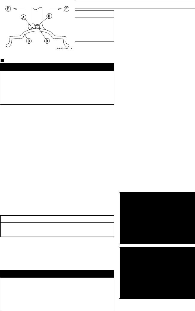
○The air valve is shown in the figure. Valve Cap [A]
Valve Core [B]
Stem Seal [C]
Valve Stem [D]
Valve Seat [E]
Valve Opened [F]
•Check the tire rotation mark on the front and rear tires and install them on the rim accordingly.
Tire Rotation Mark [A]
Rotation Direction [B]
•Position the tire on the rim so that the valve [A] align with the tire balance mark [B] (the chalk mark made during
•removal, or the yellow paint mark on a new tire).
Install the tire bead over the rim using a suitable commer-
•cially available tire changer.
Lubricate the tire beads and rim flanges with a soap and water solution or rubber lubricant to help seat the tire beads in the sealing surfaces of the rim while inflating the
•tire.
Center the rim in the tire beads, and inflate the tire with compressed air until the tire beads seat in the sealing surfaces.

 WARNING
Be sure to install the valve core whenever inflating the tire, and do not inflate the tire to more than 400 kPa (4.0 kgf/cm², 57 psi). Overinflation can explode the tire with possibility of injury and loss of life.