

- •LIST OF ABBREVIATIONS
- •New Ignition Interlock Sidestand System
- •Current Ignition Interlock Sidestand System
- •Materials of Semi-Conductor and Emitting Color
- •Units of Mass:
- •Units of Volume:
- •Units of Force:
- •Units of Length:
- •Units of Torque:
- •Units of Pressure:
- •Units of Speed:
- •Units of Power:
- •Periodic Inspection:
- •Periodic Replacement Parts:
- •Basic Torque for General Fasteners
- •Throttle Grip Free Play
- •Idle Speed
- •Engine Vacuum
- •Water and Coolant Mixture Ratio (when shipping)
- •Valve Clearance
- •Clutch Lever Free Play
- •Engine Oil
- •Tread Depth
- •Air Pressure (when cold)
- •Chain Slack
- •Drive Chain 20-link Length
- •Standard Chain
- •Pad Lining Thickness
- •Sample Diagnosis Sheet
- •Poor Running at Low Speed
- •Poor Running or No Power at High Speed:
- •Wiring Connection
- •Idle Speed
- •Wiring Connection
- •Main Throttle Sensor Resistance
- •Inlet Air Pressure Sensor Output Voltage
- •Inlet Air Temperature Sensor Output Voltage
- •Water Temperature Sensor Output Voltage
- •Atmospheric Pressure Sensor Input Voltage
- •Output Voltage at Sensor
- •Wiring Connection
- •Wiring Connection
- •Throttle Sensor Resistance
- •Stick Coil Input Voltage at ECU
- •Input Voltage at ECU
- •Subthrottle Valve Actuator Resistance
- •Subthrottle Valve Actuator Input Voltage
- •Input Voltage at Actuator
- •FI Indicator LED Light Check
- •ECU Grounding Inspection
- •ECU Power Source Inspection
- •Testing Relay
- •Fuel Pressure
- •Fuel Pressure (idling)
- •Amount of Fuel Flow
- •Testing Relay
- •Injector Power Source Voltage at ECU
- •Output Voltage at Injector Connector
- •Injector Wiring Inspection
- •Choke Lever Free Play
- •Radiator Cap Relief Pressure
- •Thermostat Valve Opening Temperature
- •Camshaft Journal, Camshaft Cap Clearance
- •Camshaft Journal Diameter
- •Camshaft Runout
- •Cylinder Compression
- •Cylinder Head Warp
- •Valve/Valve Guide Clearance (Wobble Method)
- •Valve Seating Surface Outside Diameter
- •Valve Seating Surface Width
- •Cylinder Inside Diameter
- •Piston Diameter
- •Piston Ring/Groove Clearance
- •Piston Ring Groove Width
- •Piston Ring Thickness
- •Piston Ring End Gap
- •Clutch Plate Assembly
- •Friction Plate Thickness
- •Friction and Steel Plate Warp
- •Clutch Spring Free Length
- •Oil Pressure
- •Connecting Rod Bend
- •Connecting Rod Twist
- •Connecting Rod Big End Side Clearance
- •Crankpin Diameter
- •Crankpin Diameter Marks
- •Connecting Rod Big End Inside Diameter Marks
- •Crankshaft Side Clearance
- •Crankshaft Runout
- •Crankshaft Main Journal Diameter
- •Crankshaft Main Journal Diameter Marks
- •Crankcase Main Bearing Inside Diameter Marks
- •Shift Fork Ear Thickness
- •Gear Groove Width
- •Shift Fork Guide Pin Diameter
- •Shift Drum Groove Width
- •Rim Runout
- •Axle Runout/100 mm (3.94 in.)
- •Balance Weight
- •Link Pin Outside Diameter
- •Link Plates Outside Width
- •Rear Sprocket Warp
- •Pedal Position
- •Front Disc Thickness
- •Rear Disc Thickness
- •Disc Runout
- •Oil Level (fully compressed, without spring)
- •Fork Spring Free Length
- •Rebound Damping Adjustment
- •Spring Preload Setting
- •Spring Preload Adjustment
- •Table 1 Alternator Output Voltage
- •Table 2 Stator Coil Resistance
- •Rectifier Circuit Inspection
- •Charging Voltage
- •Crankshaft Sensor Peak Voltage
- •Connections:
- •Camshaft Position Sensor Peak Voltage
- •Ignition Coil Winding Resistance
- •Primary Lead Connection
- •Connection:
- •Condition:
- •Starter Motor Brush Length
- •Commutator Diameter
- •Testing Relay
- •Testing Turn Signal Relay
- •Water Temperature Sensor
- •Fuel Level Sensor Resistance
- •Connections:
- •Fuse Circuit Inspection
- •Relay Circuit Inspection (with the battery disconnected)
- •Relay Circuit Inspection (with the battery connected)
- •Diode Circuit Inspection
- •Foreword
- •General Information
- •Battery Ground
- •Edges of Parts
- •Solvent
- •Cleaning vehicle before disassembly
- •Arrangement and Cleaning of Removed Parts
- •Storage of Removed Parts
- •Inspection
- •Replacement Parts
- •Assembly Order
- •Tightening Sequence
- •Tightening Torque
- •Force
- •Gasket, O-ring
- •Liquid Gasket, Locking Agent
- •Press
- •Ball Bearing and Needle Bearing
- •Oil Seal, Grease Seal
- •Circlips, Cotter Pins
- •Lubrication
- •Direction of Engine Rotation
- •Electrical Wires
- •ZR750–J1 Left Side View:
- •ZR750–J1 Right Side View:
- •Subthrottle Control System
- •Outline
- •Outline
- •Due Position of LED Installation
- •Honeycomb Type Catalytic Converter
- •Prefixes for Units:
- •Units of Temperature:
- •Periodic Maintenance
- •Steering Stem Nut Wrench:
- •Fuel System (DFI)
- •Fuel Hose and Connection Inspection
- •Throttle Control System Inspection
- •Engine Vacuum Synchronization Inspection
- •Air Cleaner Element Cleaning
- •Cooling System
- •Radiator Hose and Connection Inspection
- •Coolant Change
- •Engine Top End
- •Valve Clearance Inspection
- •Clutch
- •Engine Lubrication System
- •Engine Oil Change
- •Wheels/Tires
- •Tire Wear Inspection
- •Air Pressure Inspection
- •Final Drive
- •Drive Chain Slack Inspection
- •Brakes
- •Rear Brake Light Switch Connections:
- •Caliper Fluid Seal Damage
- •Brake Line Bleeding
- •Suspension
- •Steering
- •Steering Adjustment
- •Electrical System
- •General Lubrication
- •Lubrication
- •Nut, Bolt, and Fastener Tightness
- •Fuel System (DFI)
- •Terminal Names
- •Part Name
- •Oil Pressure Gauge:
- •DFI Servicing Precautions
- •Outline
- •Outline
- •DFI Diagnosis Flow Chart
- •Inquiries to Rider
- •Inquiries to Rider
- •DFI System Troubleshooting Guide
- •Self-diagnosis Outline
- •Self-diagnosis Outline
- •Self-diagnosis Procedures
- •Self-diagnosis Procedures
- •Service Code Clearing Procedures
- •How to Read Service Codes
- •How to Read Service Codes
- •How to Erase Service Codes
- •How to Erase Service Codes
- •Service Code Table
- •Service Code Table
- •Notes:
- •Backups
- •Backups
- •Main Throttle Sensor Removal/Adjustment
- •Input Voltage Inspection
- •Resistance Inspection
- •CAUTION
- •Removal
- •Installation
- •Input Voltage Inspection
- •Output Voltage Inspection
- •Removal/Installation
- •Output Voltage Inspection
- •Removal/Installation
- •Output Voltage Inspection
- •CAUTION
- •Removal
- •Input Voltage Inspection
- •Crankshaft Sensor Inspection
- •Camshaft Position Sensor Removal/Installation
- •Camshaft Position Sensor Inspection
- •Input Voltage Inspection
- •Removal
- •Installation
- •Inspection
- •Subthrottle Sensor Removal/Adjustment
- •Input Voltage Inspection
- •Removal/Installation
- •Input Voltage Inspection
- •Subthrottle Valve Actuator Removal
- •Audible Inspection
- •Input Voltage Inspection
- •Inspection Flow Chart
- •CAUTION
- •ECU Power Source Circuit
- •ECU Fuse Installation
- •ECU Main Relay Removal
- •Fuel Pressure Inspection
- •Fuel Flow Rate Inspection
- •Fuel Pump Removal
- •Operation Inspection
- •Operating Voltage Inspection
- •Pressure Regulator Removal
- •Pump Screen, Fuel Filter Cleaning
- •Fuel Pump Relay Removal
- •Removal/Installation
- •Choke Lever Operation
- •Throttle Body Assy Removal
- •Throttle Body Assy Disassembly
- •Throttle Body Assy Assembly
- •Air Cleaner Oil Draining
- •Fuel Tank Removal
- •Fuel Tank Cleaning
- •Cooling System
- •Bearing Driver:
- •Coolant Level Inspection
- •Cooling System Flushing
- •Water Pump Housing Disassembly
- •Water Pump Housing Assembly
- •Radiator and Radiator Fan Removal
- •CAUTION
- •Engine Top End
- •Exhaust System
- •Compression Gauge:
- •Camshaft Chain Tensioner Removal
- •Cylinder Compression Measurement
- •Cylinder Head Installation
- •Valve Guide Installation
- •Seat Cutter Operation Care:
- •Cylinder Installation
- •WARNING
- •Clutch
- •Clutch Holder:
- •Clutch Lever Adjustment
- •Release Shaft Removal
- •Engine Lubrication System
- •WARNING
- •Oil Pressure Measurement
- •Engine Removal/Installation
- •Crankshaft/Transmission
- •Bearing Puller:
- •Crankcase Splitting
- •Crankcase Assembly
- •Crankshaft Installation
- •Connecting Rod Installation
- •Wheels/Tires
- •Bearing Driver Set:
- •Front Wheel Installation
- •Axle Inspection
- •Tire Installation
- •Tire Repair
- •Hub Bearing Inspection
- •Final Drive
- •Bearing Driver Set:
- •Coupling Bearing Inspection
- •Brakes
- •Jack:
- •Brake Lever Position Adjustment
- •Brake Pedal Position Adjustment
- •Caliper Holder Shaft Wear
- •Rear Master Cylinder Disassembly
- •Brake Hose Removal/Installation
- •Suspension
- •Fork Cylinder Holder Handle:
- •Swingarm Installation
- •Swingarm Bearing, Sleeve Inspection
- •Steering
- •Steering Stem Nut Wrench:
- •Frame
- •Electrical System
- •Rotor Puller, M16/M18/M20/M22 × 1.5 :
- •Battery Removal
- •Initial Charge
- •Precautions
- •Alternator Inspection
- •Charging System Circuit
- •WARNING
- •Special Tool -
- •Crankshaft Sensor Peak Voltage Inspection
- •Stick Coil (Ignition Coil together with Spark Plug Cap) Removal
- •Stick Coil Primary Peak Voltage
- •IC Igniter Inspection
- •Ignition System Circuit
- •Starter Motor Removal
- •Starter Motor Installation
- •Electric Starter Circuit
- •Headlight/Tail Light Circuit (CA, AS)
- •Headlight/Tail Light Circuit (Other than CA, AS)
- •Turn Signal Light Circuit
- •Turn Signal Light Bulb Replacement
- •Radiator Fan Circuit
- •Electronic Combination Meter Unit Inspection
- •Meter Circuit
- •Rear Brake Light Switch Connections
- •Side Stand Switch Connections
- •Neutral Switch Connections
- •Oil Pressure Switch Connections*
- •Special Tool -
- •Junction Box Internal Circuit
- •30 A Main Fuse Removal
- •15 A ECU Fuse Removal
- •Appendix
- •NOTE
- •Starter motor not rotating:
- •No fuel flow:
- •Engine flooded:
- •No spark; spark weak:
- •Fuel/air mixture incorrect:
- •Compression Low:
- •Poor Running at Low Speed:
- •Spark weak:
- •Fuel/air mixture incorrect:
- •Compression low:
- •Other:
- •Poor Running or No Power at High Speed:
- •Firing incorrect:
- •Fuel/air mixture incorrect:
- •Compression low:
- •Knocking:
- •Miscellaneous:
- •Overheating:
- •Firing incorrect:
- •Muffler overheating:
- •Fuel/air mixture incorrect:
- •Compression high:
- •Engine load faulty:
- •Lubrication inadequate:
- •Gauge incorrect:
- •Coolant incorrect:
- •Cooling system component incorrect:
- •Over Cooling:
- •Gauge incorrect:
- •Cooling system component incorrect:
- •Clutch Operation Faulty:
- •Clutch slipping:
- •Clutch not disengaging properly:
- •Gear Shifting Faulty:
- •Jumps out of gear:
- •Overshifts:
- •Abnormal Engine Noise:
- •Knocking:
- •Piston slap:
- •Valve noise:
- •Other noise:
- •Abnormal Drive Train Noise:
- •Clutch noise:
- •Transmission noise:
- •Drive line noise:
- •Abnormal Frame Noise:
- •Front fork noise:
- •Rear shock absorber noise:
- •Disc brake noise:
- •Other noise:
- •Oil Pressure Warning Light Goes On:
- •Exhaust Smokes Excessively:
- •White smoke:
- •Black smoke:
- •Brown smoke:
- •Handlebar hard to turn:
- •Handlebar shakes or excessively vibrates:
- •Handlebar pulls to one side:
- •Shock absorption unsatisfactory:
- •Battery Trouble:
- •Battery discharged:
- •Battery overcharged:
4-14 COOLING SYSTEM
Radiator
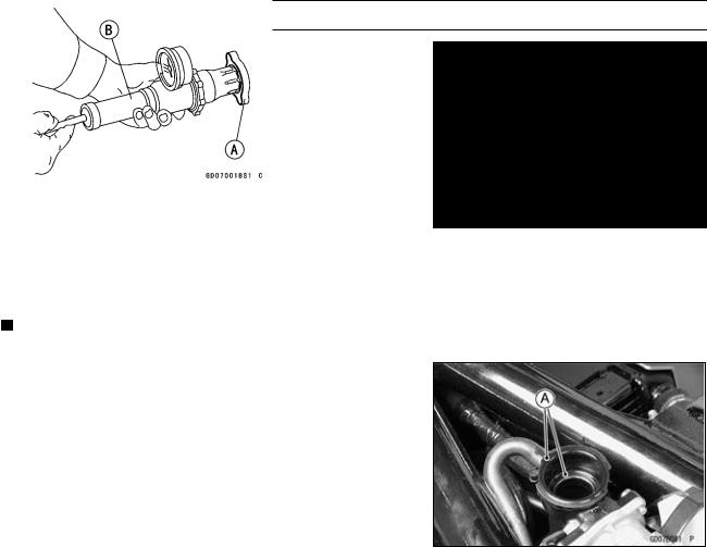
•Install the cap [A] on a cooling system pressure tester [B].
•Watching the pressure gauge, pump the pressure tester to build up the pressure until the relief valve opens: the gauge needle flicks downward. Stop pumping and measure leak time at once. The relief valve must open within the specified range in the table below and the gauge hand must remain within the same range at least 6 seconds.
Radiator Cap Relief Pressure
93 123 kPa (0.95 1.25 kgf/cm², 14 17.8 psi)
If the cap can not hold the specified pressure or if it holds too much pressure, replace it with a new one.
Radiator• Filler Neck Inspection
•Remove the fuel tank (see Fuel System (DFI) chapter).
•Remove the radiator cap.
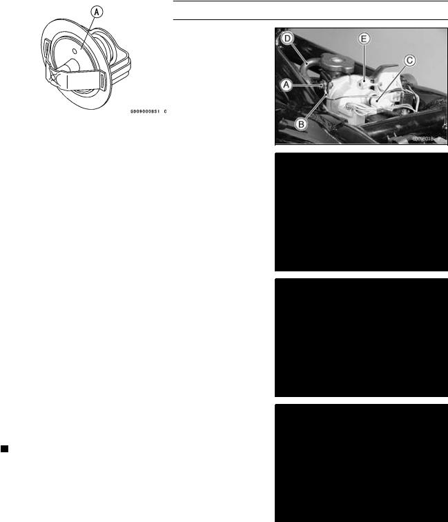
•Check the radiator filler neck for signs of damage. Check the condition of the top and bottom sealing seats [A] in the filler neck. They must be smooth and clean for the radiator cap to function properly.
COOLING SYSTEM 4-15
Thermostat
Thermostat• Removal
Drain the coolant (see Cooling System in the Periodic
•Maintenance chapter). Remove:
Fuel Tank (see Fuel System (DFI) chapter)
Thermostat Bracket Bolt [A]
Ground Lead [B]
Water Temperature Sensor Connector [C]
• Three Water Hoses [D]
Remove the thermostat housing [E].
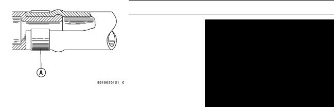
•Remove the screws [A], take off the cap [B], and take out the thermostat.
Thermostat• Installation
Install the thermostat [A] in the housing so that the air
•bleeder hole [B] is on top.
•Install a new O-ring into the housing.
Fill the radiator with coolant (see Cooling System in the
Periodic Maintenance chapter).
Thermostat• Inspection
Remove the thermostat, and inspect the thermostat valve [A] at room temperature.
If the valve is open, replace the thermostat with a new one.
4-16 COOLING SYSTEM
Thermostat
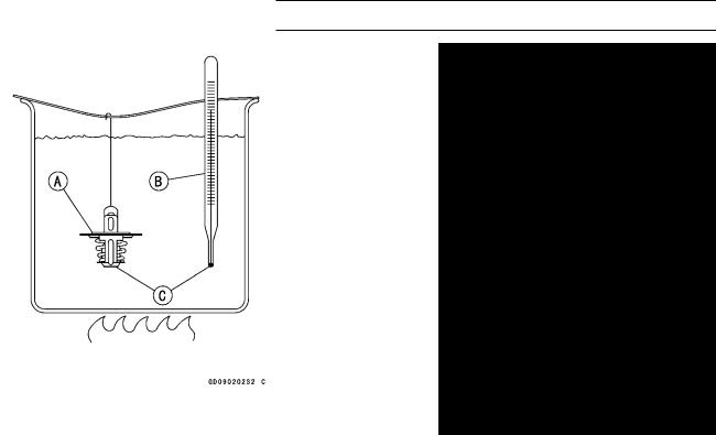
•To check valve opening temperature, suspend the thermostat [A] in a container of water and raise the temperature of the water.
○The thermostat must be completely submerged and must not touch the container sides or bottom. Suspend an accurate thermometer [B] in the water so that the heat sensitive portions [C] are located in almost the same depth. It must not touch the container, either.
If the measurement is out of the specified range, replace the thermostat with a new one.
Thermostat Valve Opening Temperature
58 62°C (136 144°F)
COOLING SYSTEM 4-17
Hoses and Pipes
Hose• Installation
Install the hoses and pipes, being careful to follow bending direction. Avoid sharp bending, kinking, flattening or
•twisting.
Run the hoses in accordance with the Cable, Wire, and
•Hose Routing section in the Appendix chapter.
Install the clamp [A] as near as possible to the hose end to clear the raised rib of the fitting. This will prevent the hoses from working loose.
○The clamp screws should be positioned correctly to prevent the clamps from contacting the other parts.
Torque - Radiator Hose Clamp Screws: 2.0 N·m (0.20 kgf·m, 17 in·lb)
Hose• Inspection
Refer to the Cooling System in the Periodic Maintenance chapter.