
- •LIST OF ABBREVIATIONS
- •New Ignition Interlock Sidestand System
- •Current Ignition Interlock Sidestand System
- •Materials of Semi-Conductor and Emitting Color
- •Units of Mass:
- •Units of Volume:
- •Units of Force:
- •Units of Length:
- •Units of Torque:
- •Units of Pressure:
- •Units of Speed:
- •Units of Power:
- •Periodic Inspection:
- •Periodic Replacement Parts:
- •Basic Torque for General Fasteners
- •Throttle Grip Free Play
- •Idle Speed
- •Engine Vacuum
- •Water and Coolant Mixture Ratio (when shipping)
- •Valve Clearance
- •Clutch Lever Free Play
- •Engine Oil
- •Tread Depth
- •Air Pressure (when cold)
- •Chain Slack
- •Drive Chain 20-link Length
- •Standard Chain
- •Pad Lining Thickness
- •Sample Diagnosis Sheet
- •Poor Running at Low Speed
- •Poor Running or No Power at High Speed:
- •Wiring Connection
- •Idle Speed
- •Wiring Connection
- •Main Throttle Sensor Resistance
- •Inlet Air Pressure Sensor Output Voltage
- •Inlet Air Temperature Sensor Output Voltage
- •Water Temperature Sensor Output Voltage
- •Atmospheric Pressure Sensor Input Voltage
- •Output Voltage at Sensor
- •Wiring Connection
- •Throttle Sensor Resistance
- •Stick Coil Input Voltage at ECU
- •Input Voltage at ECU
- •Subthrottle Valve Actuator Resistance
- •Subthrottle Valve Actuator Input Voltage
- •Input Voltage at Actuator
- •FI Indicator LED Light Check
- •ECU Grounding Inspection
- •ECU Power Source Inspection
- •Testing Relay
- •Fuel Pressure
- •Fuel Pressure (idling)
- •Amount of Fuel Flow
- •Testing Relay
- •Injector Power Source Voltage at ECU
- •Output Voltage at Injector Connector
- •Injector Wiring Inspection
- •Choke Lever Free Play
- •Radiator Cap Relief Pressure
- •Thermostat Valve Opening Temperature
- •Camshaft Journal, Camshaft Cap Clearance
- •Camshaft Journal Diameter
- •Camshaft Runout
- •Cylinder Compression
- •Cylinder Head Warp
- •Valve/Valve Guide Clearance (Wobble Method)
- •Valve Seating Surface Outside Diameter
- •Valve Seating Surface Width
- •Cylinder Inside Diameter
- •Piston Diameter
- •Piston Ring/Groove Clearance
- •Piston Ring Groove Width
- •Piston Ring Thickness
- •Piston Ring End Gap
- •Clutch Plate Assembly
- •Friction Plate Thickness
- •Friction and Steel Plate Warp
- •Clutch Spring Free Length
- •Oil Pressure
- •Connecting Rod Bend
- •Connecting Rod Twist
- •Connecting Rod Big End Side Clearance
- •Crankpin Diameter
- •Crankpin Diameter Marks
- •Connecting Rod Big End Inside Diameter Marks
- •Crankshaft Side Clearance
- •Crankshaft Runout
- •Crankshaft Main Journal Diameter
- •Crankshaft Main Journal Diameter Marks
- •Crankcase Main Bearing Inside Diameter Marks
- •Shift Fork Ear Thickness
- •Gear Groove Width
- •Shift Fork Guide Pin Diameter
- •Shift Drum Groove Width
- •Rim Runout
- •Axle Runout/100 mm (3.94 in.)
- •Balance Weight
- •Link Pin Outside Diameter
- •Link Plates Outside Width
- •Rear Sprocket Warp
- •Pedal Position
- •Front Disc Thickness
- •Rear Disc Thickness
- •Disc Runout
- •Oil Level (fully compressed, without spring)
- •Fork Spring Free Length
- •Rebound Damping Adjustment
- •Spring Preload Setting
- •Spring Preload Adjustment
- •Table 1 Alternator Output Voltage
- •Table 2 Stator Coil Resistance
- •Rectifier Circuit Inspection
- •Charging Voltage
- •Crankshaft Sensor Peak Voltage
- •Connections:
- •Camshaft Position Sensor Peak Voltage
- •Ignition Coil Winding Resistance
- •Primary Lead Connection
- •Connection:
- •Condition:
- •Starter Motor Brush Length
- •Commutator Diameter
- •Testing Relay
- •Testing Turn Signal Relay
- •Water Temperature Sensor
- •Fuel Level Sensor Resistance
- •Connections:
- •Fuse Circuit Inspection
- •Relay Circuit Inspection (with the battery disconnected)
- •Relay Circuit Inspection (with the battery connected)
- •Diode Circuit Inspection
- •Foreword
- •General Information
- •Battery Ground
- •Edges of Parts
- •Solvent
- •Cleaning vehicle before disassembly
- •Arrangement and Cleaning of Removed Parts
- •Storage of Removed Parts
- •Inspection
- •Replacement Parts
- •Assembly Order
- •Tightening Sequence
- •Tightening Torque
- •Force
- •Gasket, O-ring
- •Liquid Gasket, Locking Agent
- •Press
- •Ball Bearing and Needle Bearing
- •Oil Seal, Grease Seal
- •Circlips, Cotter Pins
- •Lubrication
- •Direction of Engine Rotation
- •Electrical Wires
- •ZR750–J1 Left Side View:
- •ZR750–J1 Right Side View:
- •Subthrottle Control System
- •Outline
- •Outline
- •Due Position of LED Installation
- •Honeycomb Type Catalytic Converter
- •Prefixes for Units:
- •Units of Temperature:
- •Periodic Maintenance
- •Steering Stem Nut Wrench:
- •Fuel System (DFI)
- •Fuel Hose and Connection Inspection
- •Throttle Control System Inspection
- •Engine Vacuum Synchronization Inspection
- •Air Cleaner Element Cleaning
- •Cooling System
- •Radiator Hose and Connection Inspection
- •Coolant Change
- •Engine Top End
- •Valve Clearance Inspection
- •Clutch
- •Engine Lubrication System
- •Engine Oil Change
- •Wheels/Tires
- •Tire Wear Inspection
- •Air Pressure Inspection
- •Final Drive
- •Drive Chain Slack Inspection
- •Brakes
- •Rear Brake Light Switch Connections:
- •Caliper Fluid Seal Damage
- •Brake Line Bleeding
- •Suspension
- •Steering
- •Steering Adjustment
- •Electrical System
- •General Lubrication
- •Lubrication
- •Nut, Bolt, and Fastener Tightness
- •Fuel System (DFI)
- •Terminal Names
- •Part Name
- •Oil Pressure Gauge:
- •DFI Servicing Precautions
- •Outline
- •Outline
- •DFI Diagnosis Flow Chart
- •Inquiries to Rider
- •DFI System Troubleshooting Guide
- •Self-diagnosis Outline
- •Self-diagnosis Procedures
- •Service Code Clearing Procedures
- •How to Read Service Codes
- •How to Erase Service Codes
- •Service Code Table
- •Notes:
- •Backups
- •Backups
- •Main Throttle Sensor Removal/Adjustment
- •Input Voltage Inspection
- •Resistance Inspection
- •CAUTION
- •Removal
- •Installation
- •Input Voltage Inspection
- •Output Voltage Inspection
- •Removal/Installation
- •Output Voltage Inspection
- •Removal/Installation
- •Output Voltage Inspection
- •CAUTION
- •Removal
- •Input Voltage Inspection
- •Crankshaft Sensor Inspection
- •Camshaft Position Sensor Removal/Installation
- •Camshaft Position Sensor Inspection
- •Input Voltage Inspection
- •Removal
- •Installation
- •Inspection
- •Subthrottle Sensor Removal/Adjustment
- •Input Voltage Inspection
- •Removal/Installation
- •Input Voltage Inspection
- •Subthrottle Valve Actuator Removal
- •Audible Inspection
- •Input Voltage Inspection
- •Inspection Flow Chart
- •CAUTION
- •ECU Power Source Circuit
- •ECU Fuse Installation
- •ECU Main Relay Removal
- •Fuel Pressure Inspection
- •Fuel Flow Rate Inspection
- •Fuel Pump Removal
- •Operation Inspection
- •Operating Voltage Inspection
- •Pressure Regulator Removal
- •Pump Screen, Fuel Filter Cleaning
- •Fuel Pump Relay Removal
- •Removal/Installation
- •Choke Lever Operation
- •Throttle Body Assy Removal
- •Throttle Body Assy Disassembly
- •Throttle Body Assy Assembly
- •Air Cleaner Oil Draining
- •Fuel Tank Removal
- •Fuel Tank Cleaning
- •Cooling System
- •Bearing Driver:
- •Coolant Level Inspection
- •Cooling System Flushing
- •Water Pump Housing Disassembly
- •Water Pump Housing Assembly
- •Radiator and Radiator Fan Removal
- •CAUTION
- •Engine Top End
- •Exhaust System
- •Compression Gauge:
- •Camshaft Chain Tensioner Removal
- •Cylinder Compression Measurement
- •Cylinder Head Installation
- •Valve Guide Installation
- •Seat Cutter Operation Care:
- •Cylinder Installation
- •WARNING
- •Clutch
- •Clutch Holder:
- •Clutch Lever Adjustment
- •Release Shaft Removal
- •Engine Lubrication System
- •WARNING
- •Oil Pressure Measurement
- •Engine Removal/Installation
- •Crankshaft/Transmission
- •Bearing Puller:
- •Crankcase Splitting
- •Crankcase Assembly
- •Crankshaft Installation
- •Connecting Rod Installation
- •Wheels/Tires
- •Bearing Driver Set:
- •Front Wheel Installation
- •Axle Inspection
- •Tire Installation
- •Tire Repair
- •Hub Bearing Inspection
- •Final Drive
- •Bearing Driver Set:
- •Coupling Bearing Inspection
- •Brakes
- •Jack:
- •Brake Lever Position Adjustment
- •Brake Pedal Position Adjustment
- •Caliper Holder Shaft Wear
- •Rear Master Cylinder Disassembly
- •Brake Hose Removal/Installation
- •Suspension
- •Fork Cylinder Holder Handle:
- •Swingarm Installation
- •Swingarm Bearing, Sleeve Inspection
- •Steering
- •Steering Stem Nut Wrench:
- •Frame
- •Electrical System
- •Rotor Puller, M16/M18/M20/M22 × 1.5 :
- •Battery Removal
- •Initial Charge
- •Precautions
- •Alternator Inspection
- •Charging System Circuit
- •WARNING
- •Special Tool -
- •Crankshaft Sensor Peak Voltage Inspection
- •Stick Coil (Ignition Coil together with Spark Plug Cap) Removal
- •Stick Coil Primary Peak Voltage
- •IC Igniter Inspection
- •Ignition System Circuit
- •Starter Motor Removal
- •Starter Motor Installation
- •Electric Starter Circuit
- •Headlight/Tail Light Circuit (CA, AS)
- •Headlight/Tail Light Circuit (Other than CA, AS)
- •Turn Signal Light Circuit
- •Turn Signal Light Bulb Replacement
- •Radiator Fan Circuit
- •Electronic Combination Meter Unit Inspection
- •Meter Circuit
- •Rear Brake Light Switch Connections
- •Side Stand Switch Connections
- •Neutral Switch Connections
- •Oil Pressure Switch Connections*
- •Special Tool -
- •Junction Box Internal Circuit
- •30 A Main Fuse Removal
- •15 A ECU Fuse Removal
- •Appendix
- •NOTE
- •Starter motor not rotating:
- •No fuel flow:
- •Engine flooded:
- •No spark; spark weak:
- •Fuel/air mixture incorrect:
- •Compression Low:
- •Poor Running at Low Speed:
- •Spark weak:
- •Fuel/air mixture incorrect:
- •Compression low:
- •Other:
- •Poor Running or No Power at High Speed:
- •Firing incorrect:
- •Fuel/air mixture incorrect:
- •Compression low:
- •Knocking:
- •Miscellaneous:
- •Overheating:
- •Firing incorrect:
- •Muffler overheating:
- •Fuel/air mixture incorrect:
- •Compression high:
- •Engine load faulty:
- •Lubrication inadequate:
- •Gauge incorrect:
- •Coolant incorrect:
- •Cooling system component incorrect:
- •Over Cooling:
- •Gauge incorrect:
- •Cooling system component incorrect:
- •Clutch Operation Faulty:
- •Clutch slipping:
- •Clutch not disengaging properly:
- •Gear Shifting Faulty:
- •Jumps out of gear:
- •Overshifts:
- •Abnormal Engine Noise:
- •Knocking:
- •Piston slap:
- •Valve noise:
- •Other noise:
- •Abnormal Drive Train Noise:
- •Clutch noise:
- •Transmission noise:
- •Drive line noise:
- •Abnormal Frame Noise:
- •Front fork noise:
- •Rear shock absorber noise:
- •Disc brake noise:
- •Other noise:
- •Oil Pressure Warning Light Goes On:
- •Exhaust Smokes Excessively:
- •White smoke:
- •Black smoke:
- •Brown smoke:
- •Handlebar hard to turn:
- •Handlebar shakes or excessively vibrates:
- •Handlebar pulls to one side:
- •Shock absorption unsatisfactory:
- •Battery Trouble:
- •Battery discharged:
- •Battery overcharged:

GENERAL INFORMATION 1-7
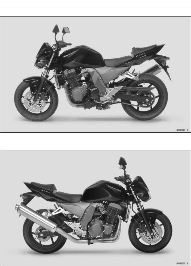
Model Identification
ZR750–J1 Left Side View:
ZR750–J1 Right Side View:

1-8 GENERAL INFORMATION
General Specifications
|
|
|
Items |
|
ZR750–J1 |
Dimensions: |
|
|
Overall length |
|
2 080 mm (81.9 in.) |
Overall width |
|
780 mm (30.7 in.) |
Overall height |
|
1 055 mm (41.5 in.) |
Wheelbase |
|
1 425 mm (56.1 in.) |
Road clearance |
|
165 mm (6.5 in.) |
Seat height |
|
815 mm (32.1 in.) |
Dry mass |
|
195 kg (430.0 lb) |
Curb mass: |
Front |
111 kg (244.8 lb) |
|
Rear |
107 kg (235.9 lb) |
Fuel tank capacity |
|
18 L (5.0 US gal.) |
Performance: |
|
|
Minimum turning radius |
2.9 m (9.5 ft) |
|
Engine: |
|
|
Type |
|
4-stroke, DOHC, 4-cylinder |
Cooling system |
|
Liquid-cooled |
Bore and stroke |
|
68.4 × 50.9 mm (2.7 × 2.0 in.) |
Displacement |
|
748 mL (45.64 cu in.) |
Compression ratio |
|
11.3 |
Maximum horsepower |
|
79 kW (107 PS) @10 500 r/min (rpm), |
|
|
(MY, AU) 80 kW (109 PS) @11 000 r/min (rpm) |
|
|
(HR) 78.2 kW (106 PS) @11 000 r/min (rpm) |
Maximum torque |
|
75 N·m (7.6 kgf·m, 55 ft·lb) @8 200 r/min (rpm), |
|
|
(HR) 73 N·m (7.4 kgf·m, 54 ft·lb) @8 200 r/min (rpm) |
Carburetion system |
|
FI (Fuel Injection) KEIHIN TTK34 × 4 |
Starting system |
|
Electric starter |
Ignition system |
|
Battery and coil (transistorized) |
Timing advance |
|
Electronically advanced (digital igniter) |
Ignition timing |
|
From 10° BTDC @1 100 r/min (rpm) to 37° BTDC |
|
|
@5 800 r/min (rpm) |
Spark plug |
|
NGK CR9EK or ND U27ETR |
Cylinder numbering method |
Left to right, 1-2-3-4 |
|
Firing order |
|
1-2-4-3 |
Valve timing: |
|
|
Inlet |
Open |
38° BTDC |
|
Close |
66° ABDC |
|
Duration |
284° |
Exhaust |
Open |
57° BBDC |
|
Close |
31° ATDC |
|
Duration |
268° |
Lubrication system |
|
Forced lubrication (wet sump) |
Engine oil: |
|
|
Type |
|
API SE, SF or SG |
|
|
API SH or SJ with JASO MA |

|
|
|
|
GENERAL INFORMATION 1-9 |
|
|
|
||
|
General Specifications |
|
|
|
|
|
|
|
|
|
|
|
|
|
|
Items |
|
|
ZR750–J1 |
|
Viscosity |
|
SAE 10W-40 |
|
|
Capacity |
|
3.8 L (4.0 US qt) |
|
|
Drive Train: |
|
|
|
|
Primary reduction system: |
|
|
|
|
Type |
|
Gear |
|
|
Reduction ratio |
|
1.714 |
(84/49) |
|
Clutch type |
|
Wet multi disc |
|
|
Transmission: |
|
|
|
|
Type |
|
6-speed, constant mesh, return shift |
|
|
Gear ratios: |
1st |
2.571 |
(36/14) |
|
|
2nd |
1.941 |
(33/17) |
|
|
3rd |
1.555 |
(28/18) |
|
|
4th |
1.333 |
(28/21) |
|
|
5th |
1.200 |
(24/20) |
|
|
6th |
1.095 |
(23/21) |
|
Final drive system: |
|
|
|
|
Type |
|
Chain drive |
|
|
Reduction ratio |
|
2.867 |
(43/15) |
|
Overall drive ratio |
|
5.382 |
@Top gear |
|
Frame: |
|
|
|
|
Type |
|
Tubular, diamond |
|
|
Caster (rake angle) |
|
24.5° |
|
|
Trail |
|
104 mm (4.1 in.) |
|
|
Front tire: |
Type |
Tubeless |
|
|
|
Size |
120/70 ZR17 M/C (58W) |
|
|
Rear tire: |
Type |
Tubeless |
|
|
|
Size |
180/55 ZR17 M/C (73W) |
|
|
Front suspension: |
Type |
Telescopic fork (upside-down) |
|
|
|
Wheel travel |
120 mm (4.7 in.) |
|
|
Rear suspension: |
Type |
Swingarm (uni-trak) |
|
|
|
Wheel travel |
126 mm (5.0 in.) |
|
|
Brake Type: |
Front |
Dual discs |
|
|
|
Rear |
Single disc |
|
|
Electrical Equipment: |
|
|
|
|
Battery |
|
12 V 8 Ah |
|
|
Headlight: |
Type |
Semi-sealed beam |
|
|
|
Bulb |
12 V 55 W × 2/55 W (Hi/Lo) |
|
|
Tail/brake light |
|
12 V 0.5/3.8 W (LED), (CA) 12 V 0.5/5W (LED) |
|
|
Alternator: |
Type |
Three-phase AC |
|
|
|
Rated output |
24 A/14 V @5 000 r/min (rpm) |
Specifications are subject to change without notice, and may not apply to every country. (AU): Australia Model
(CA): Canada Model
(MY): Malaysia Model
(HR): with Honeycomb Catalytic Converter Model (Restricted model)

1-10 GENERAL INFORMATION
Technical Information – Air Inlet System
Subthrottle Control System
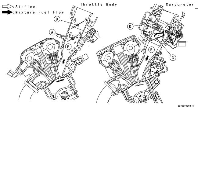
The ZR750–J1 employs large bore throttle bodies to increase power output. However, sudden changes in throttle opening can cause hesitation and jerky throttle response with a single butterfly valve in a large bore. Therefore two throttle valves are placed in each inlet tract, the main throttle valve located closest to the cylinder and a subthrottle valve placed further up the inlet tract. The main throttle valve is operated by the rider when the throttle grip is turned clockwise or counterclockwise, while the subthrottle valve is operated by a stepping motor controlled by the ECU. The subthrottle valve automatically adjusts air inlet to more precisely match engine demand, so that when the main throttle is opened quickly there is no hesitation or jerky response.
The subthrottle valves allow the fuel injection system to provide smooth throttle response, similar to that of a constant velocity carburetor, no matter how quickly the throttle is opened.
|
|
|
A. Main Throttle Valve |
D. Vacuum Piston |
|
B. Subthrottle Valve |
E. Inlet Air |
|
C. Throttle Valve |
|
|

GENERAL INFORMATION 1-11
Technical Information – Air Inlet System
Operation
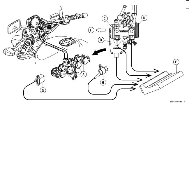
The subthrottle control system consists of the subthrottle valve, subthrottle valve actuator with a stepping motor built in it, ECU, and subthrottle sensor. The subthrottle valve is built in the each throttle body.
The subthrottle control system operates on the signal supplied from the ECU. The open/close operation of the subthrottle valve is performed by the subthrottle actuator which is controlled by the ECU to change the current direction into the motor of the subthrottle valve actuator.
The subthrottle sensor detects the subthrottle valve actuator movement by measuring voltage and the ECU determines the subthrottle valve angle based on the operation map.
When turning the ignition switch ON, every time the ECU automatically drives the subthrottle valve from fully closed position to fully opened position. The ECU memorizes these positions and turns back the subthrottle valve to the original point to confirm the subthrottle valve idling voltage.
|
|
|
|
A. Subthrottle Valves |
E. ECU (Electric Control Unit) |
B. Subthrottle Valve Actuator |
F. Air Cleaner Side |
C. Subthrottle Sensor |
G. Crankshaft Sensor |
D. Main Throttle Sensor |
H. Speed Sensor |