
- •LIST OF ABBREVIATIONS
- •New Ignition Interlock Sidestand System
- •Current Ignition Interlock Sidestand System
- •Materials of Semi-Conductor and Emitting Color
- •Units of Mass:
- •Units of Volume:
- •Units of Force:
- •Units of Length:
- •Units of Torque:
- •Units of Pressure:
- •Units of Speed:
- •Units of Power:
- •Periodic Inspection:
- •Periodic Replacement Parts:
- •Basic Torque for General Fasteners
- •Throttle Grip Free Play
- •Idle Speed
- •Engine Vacuum
- •Water and Coolant Mixture Ratio (when shipping)
- •Valve Clearance
- •Clutch Lever Free Play
- •Engine Oil
- •Tread Depth
- •Air Pressure (when cold)
- •Chain Slack
- •Drive Chain 20-link Length
- •Standard Chain
- •Pad Lining Thickness
- •Sample Diagnosis Sheet
- •Poor Running at Low Speed
- •Poor Running or No Power at High Speed:
- •Wiring Connection
- •Idle Speed
- •Wiring Connection
- •Main Throttle Sensor Resistance
- •Inlet Air Pressure Sensor Output Voltage
- •Inlet Air Temperature Sensor Output Voltage
- •Water Temperature Sensor Output Voltage
- •Atmospheric Pressure Sensor Input Voltage
- •Output Voltage at Sensor
- •Wiring Connection
- •Throttle Sensor Resistance
- •Stick Coil Input Voltage at ECU
- •Input Voltage at ECU
- •Subthrottle Valve Actuator Resistance
- •Subthrottle Valve Actuator Input Voltage
- •Input Voltage at Actuator
- •FI Indicator LED Light Check
- •ECU Grounding Inspection
- •ECU Power Source Inspection
- •Testing Relay
- •Fuel Pressure
- •Fuel Pressure (idling)
- •Amount of Fuel Flow
- •Testing Relay
- •Injector Power Source Voltage at ECU
- •Output Voltage at Injector Connector
- •Injector Wiring Inspection
- •Choke Lever Free Play
- •Radiator Cap Relief Pressure
- •Thermostat Valve Opening Temperature
- •Camshaft Journal, Camshaft Cap Clearance
- •Camshaft Journal Diameter
- •Camshaft Runout
- •Cylinder Compression
- •Cylinder Head Warp
- •Valve/Valve Guide Clearance (Wobble Method)
- •Valve Seating Surface Outside Diameter
- •Valve Seating Surface Width
- •Cylinder Inside Diameter
- •Piston Diameter
- •Piston Ring/Groove Clearance
- •Piston Ring Groove Width
- •Piston Ring Thickness
- •Piston Ring End Gap
- •Clutch Plate Assembly
- •Friction Plate Thickness
- •Friction and Steel Plate Warp
- •Clutch Spring Free Length
- •Oil Pressure
- •Connecting Rod Bend
- •Connecting Rod Twist
- •Connecting Rod Big End Side Clearance
- •Crankpin Diameter
- •Crankpin Diameter Marks
- •Connecting Rod Big End Inside Diameter Marks
- •Crankshaft Side Clearance
- •Crankshaft Runout
- •Crankshaft Main Journal Diameter
- •Crankshaft Main Journal Diameter Marks
- •Crankcase Main Bearing Inside Diameter Marks
- •Shift Fork Ear Thickness
- •Gear Groove Width
- •Shift Fork Guide Pin Diameter
- •Shift Drum Groove Width
- •Rim Runout
- •Axle Runout/100 mm (3.94 in.)
- •Balance Weight
- •Link Pin Outside Diameter
- •Link Plates Outside Width
- •Rear Sprocket Warp
- •Pedal Position
- •Front Disc Thickness
- •Rear Disc Thickness
- •Disc Runout
- •Oil Level (fully compressed, without spring)
- •Fork Spring Free Length
- •Rebound Damping Adjustment
- •Spring Preload Setting
- •Spring Preload Adjustment
- •Table 1 Alternator Output Voltage
- •Table 2 Stator Coil Resistance
- •Rectifier Circuit Inspection
- •Charging Voltage
- •Crankshaft Sensor Peak Voltage
- •Connections:
- •Camshaft Position Sensor Peak Voltage
- •Ignition Coil Winding Resistance
- •Primary Lead Connection
- •Connection:
- •Condition:
- •Starter Motor Brush Length
- •Commutator Diameter
- •Testing Relay
- •Testing Turn Signal Relay
- •Water Temperature Sensor
- •Fuel Level Sensor Resistance
- •Connections:
- •Fuse Circuit Inspection
- •Relay Circuit Inspection (with the battery disconnected)
- •Relay Circuit Inspection (with the battery connected)
- •Diode Circuit Inspection
- •Foreword
- •General Information
- •Battery Ground
- •Edges of Parts
- •Solvent
- •Cleaning vehicle before disassembly
- •Arrangement and Cleaning of Removed Parts
- •Storage of Removed Parts
- •Inspection
- •Replacement Parts
- •Assembly Order
- •Tightening Sequence
- •Tightening Torque
- •Force
- •Gasket, O-ring
- •Liquid Gasket, Locking Agent
- •Press
- •Ball Bearing and Needle Bearing
- •Oil Seal, Grease Seal
- •Circlips, Cotter Pins
- •Lubrication
- •Direction of Engine Rotation
- •Electrical Wires
- •ZR750–J1 Left Side View:
- •ZR750–J1 Right Side View:
- •Subthrottle Control System
- •Outline
- •Outline
- •Due Position of LED Installation
- •Honeycomb Type Catalytic Converter
- •Prefixes for Units:
- •Units of Temperature:
- •Periodic Maintenance
- •Steering Stem Nut Wrench:
- •Fuel System (DFI)
- •Fuel Hose and Connection Inspection
- •Throttle Control System Inspection
- •Engine Vacuum Synchronization Inspection
- •Air Cleaner Element Cleaning
- •Cooling System
- •Radiator Hose and Connection Inspection
- •Coolant Change
- •Engine Top End
- •Valve Clearance Inspection
- •Clutch
- •Engine Lubrication System
- •Engine Oil Change
- •Wheels/Tires
- •Tire Wear Inspection
- •Air Pressure Inspection
- •Final Drive
- •Drive Chain Slack Inspection
- •Brakes
- •Rear Brake Light Switch Connections:
- •Caliper Fluid Seal Damage
- •Brake Line Bleeding
- •Suspension
- •Steering
- •Steering Adjustment
- •Electrical System
- •General Lubrication
- •Lubrication
- •Nut, Bolt, and Fastener Tightness
- •Fuel System (DFI)
- •Terminal Names
- •Part Name
- •Oil Pressure Gauge:
- •DFI Servicing Precautions
- •Outline
- •Outline
- •DFI Diagnosis Flow Chart
- •Inquiries to Rider
- •DFI System Troubleshooting Guide
- •Self-diagnosis Outline
- •Self-diagnosis Procedures
- •Service Code Clearing Procedures
- •How to Read Service Codes
- •How to Erase Service Codes
- •Service Code Table
- •Notes:
- •Backups
- •Backups
- •Main Throttle Sensor Removal/Adjustment
- •Input Voltage Inspection
- •Resistance Inspection
- •CAUTION
- •Removal
- •Installation
- •Input Voltage Inspection
- •Output Voltage Inspection
- •Removal/Installation
- •Output Voltage Inspection
- •Removal/Installation
- •Output Voltage Inspection
- •CAUTION
- •Removal
- •Input Voltage Inspection
- •Crankshaft Sensor Inspection
- •Camshaft Position Sensor Removal/Installation
- •Camshaft Position Sensor Inspection
- •Input Voltage Inspection
- •Removal
- •Installation
- •Inspection
- •Subthrottle Sensor Removal/Adjustment
- •Input Voltage Inspection
- •Removal/Installation
- •Input Voltage Inspection
- •Subthrottle Valve Actuator Removal
- •Audible Inspection
- •Input Voltage Inspection
- •Inspection Flow Chart
- •CAUTION
- •ECU Power Source Circuit
- •ECU Fuse Installation
- •ECU Main Relay Removal
- •Fuel Pressure Inspection
- •Fuel Flow Rate Inspection
- •Fuel Pump Removal
- •Operation Inspection
- •Operating Voltage Inspection
- •Pressure Regulator Removal
- •Pump Screen, Fuel Filter Cleaning
- •Fuel Pump Relay Removal
- •Removal/Installation
- •Choke Lever Operation
- •Throttle Body Assy Removal
- •Throttle Body Assy Disassembly
- •Throttle Body Assy Assembly
- •Air Cleaner Oil Draining
- •Fuel Tank Removal
- •Fuel Tank Cleaning
- •Cooling System
- •Bearing Driver:
- •Coolant Level Inspection
- •Cooling System Flushing
- •Water Pump Housing Disassembly
- •Water Pump Housing Assembly
- •Radiator and Radiator Fan Removal
- •CAUTION
- •Engine Top End
- •Exhaust System
- •Compression Gauge:
- •Camshaft Chain Tensioner Removal
- •Cylinder Compression Measurement
- •Cylinder Head Installation
- •Valve Guide Installation
- •Seat Cutter Operation Care:
- •Cylinder Installation
- •WARNING
- •Clutch
- •Clutch Holder:
- •Clutch Lever Adjustment
- •Release Shaft Removal
- •Engine Lubrication System
- •WARNING
- •Oil Pressure Measurement
- •Engine Removal/Installation
- •Crankshaft/Transmission
- •Bearing Puller:
- •Crankcase Splitting
- •Crankcase Assembly
- •Crankshaft Installation
- •Connecting Rod Installation
- •Wheels/Tires
- •Bearing Driver Set:
- •Front Wheel Installation
- •Axle Inspection
- •Tire Installation
- •Tire Repair
- •Hub Bearing Inspection
- •Final Drive
- •Bearing Driver Set:
- •Coupling Bearing Inspection
- •Brakes
- •Jack:
- •Brake Lever Position Adjustment
- •Brake Pedal Position Adjustment
- •Caliper Holder Shaft Wear
- •Rear Master Cylinder Disassembly
- •Brake Hose Removal/Installation
- •Suspension
- •Fork Cylinder Holder Handle:
- •Swingarm Installation
- •Swingarm Bearing, Sleeve Inspection
- •Steering
- •Steering Stem Nut Wrench:
- •Frame
- •Electrical System
- •Rotor Puller, M16/M18/M20/M22 × 1.5 :
- •Battery Removal
- •Initial Charge
- •Precautions
- •Alternator Inspection
- •Charging System Circuit
- •WARNING
- •Special Tool -
- •Crankshaft Sensor Peak Voltage Inspection
- •Stick Coil (Ignition Coil together with Spark Plug Cap) Removal
- •Stick Coil Primary Peak Voltage
- •IC Igniter Inspection
- •Ignition System Circuit
- •Starter Motor Removal
- •Starter Motor Installation
- •Electric Starter Circuit
- •Headlight/Tail Light Circuit (CA, AS)
- •Headlight/Tail Light Circuit (Other than CA, AS)
- •Turn Signal Light Circuit
- •Turn Signal Light Bulb Replacement
- •Radiator Fan Circuit
- •Electronic Combination Meter Unit Inspection
- •Meter Circuit
- •Rear Brake Light Switch Connections
- •Side Stand Switch Connections
- •Neutral Switch Connections
- •Oil Pressure Switch Connections*
- •Special Tool -
- •Junction Box Internal Circuit
- •30 A Main Fuse Removal
- •15 A ECU Fuse Removal
- •Appendix
- •NOTE
- •Starter motor not rotating:
- •No fuel flow:
- •Engine flooded:
- •No spark; spark weak:
- •Fuel/air mixture incorrect:
- •Compression Low:
- •Poor Running at Low Speed:
- •Spark weak:
- •Fuel/air mixture incorrect:
- •Compression low:
- •Other:
- •Poor Running or No Power at High Speed:
- •Firing incorrect:
- •Fuel/air mixture incorrect:
- •Compression low:
- •Knocking:
- •Miscellaneous:
- •Overheating:
- •Firing incorrect:
- •Muffler overheating:
- •Fuel/air mixture incorrect:
- •Compression high:
- •Engine load faulty:
- •Lubrication inadequate:
- •Gauge incorrect:
- •Coolant incorrect:
- •Cooling system component incorrect:
- •Over Cooling:
- •Gauge incorrect:
- •Cooling system component incorrect:
- •Clutch Operation Faulty:
- •Clutch slipping:
- •Clutch not disengaging properly:
- •Gear Shifting Faulty:
- •Jumps out of gear:
- •Overshifts:
- •Abnormal Engine Noise:
- •Knocking:
- •Piston slap:
- •Valve noise:
- •Other noise:
- •Abnormal Drive Train Noise:
- •Clutch noise:
- •Transmission noise:
- •Drive line noise:
- •Abnormal Frame Noise:
- •Front fork noise:
- •Rear shock absorber noise:
- •Disc brake noise:
- •Other noise:
- •Oil Pressure Warning Light Goes On:
- •Exhaust Smokes Excessively:
- •White smoke:
- •Black smoke:
- •Brown smoke:
- •Handlebar hard to turn:
- •Handlebar shakes or excessively vibrates:
- •Handlebar pulls to one side:
- •Shock absorption unsatisfactory:
- •Battery Trouble:
- •Battery discharged:
- •Battery overcharged:

FUEL SYSTEM (DFI) 3-17
Troubleshooting the DFI System
Outline
Outline
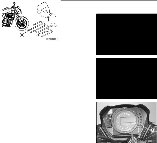
When an abnormality in the system occurs, the FI indicator LED (Light Emitting Diode) light goes on to alert the rider on the meter panel. In addition, the condition of the problem is stored in the memory of the ECU (electronic control unit). With the engine stopped and turned in the self-diagnosis mode, the service code [A] is indicated by the number of times the FI indicator LED light blinks.
When due to a malfunction, the FI indicator LED light remains lit, ask the rider about the conditions [B] under which the• problem occurred and try to determine the cause [C].
First, conduct a self-diagnosis inspection and then a non -self-diagnosis inspection. The non–self–diagnosis items are not indicated by the FI indicator LED light. Don’t rely solely on the DFI self-diagnosis function, use common sense.
Even when the DFI system is operating normally, the FI indicator LED light [A] may light up under strong electrical interference. No repair needed. Turn the ignition SW (switch) OFF to stop the indicator light.
When the FI indicator LED light goes on and the motorcycle is brought in for repair, check the service codes.
When the repair has been done, the LED light doesn’t go on. But the service codes stored in memory are not erased to preserve the problem history, and the LED light can display the codes in the self-diagnosis mode. The problem history is referred when solving unstable problems.
When the motorcycle is down, the vehicle-down sensor is turned OFF and the ECU shuts off the fuel injectors and ignition system. The FI indicator LED light blinks but the fault code cannot be displayed. The ignition SW is left ON. If the starter button is pushed, the electric starter turns but the engine doesn’t start. To start the engine again, raise the motorcycle, turn the ignition SW OFF, and then ON. The vehicle-down sensor is turned ON and the LED light goes OFF.

3-18 FUEL SYSTEM (DFI)
Troubleshooting the DFI System
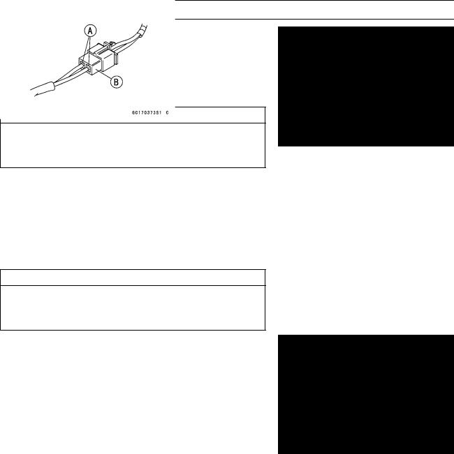
○The DFI part connectors [A] have seals [B], including the
•ECU.
Join the connector and insert the needle adapters (special tool) [C] inside the seals [B] from behind the connector until the adapter reaches the terminal.
Special Tool - Needle Adapter Set: 57001–1457
CAUTION
Insert the needle adapter straight along the terminal in the connector to prevent short-circuit between terminals.
•Make sure that measuring points are correct in the connector, noting the position of the lock [D] and the lead color before measurement. Do not reverse connections
•of the hand tester or a digital meter.
Be careful not to short-circuit the leads of the DFI or elec-
•trical system parts by contact between adapters.
Turn the ignition SW ON and measure the voltage with the connector joined.
CAUTION
Incorrect, reverse connection or short circuit by needle adapters could damage the DFI or electrical system parts.
○After measurement, remove the needle adapters and apply silicone sealant to the seals [A] of the connector [B] for waterproofing.
•Always check battery condition before replacing the DFI parts. A fully charged battery is a must for conducting accurate tests of the DFI system.
•Trouble may involve one or in some cases all items. Never replace a defective part without determining what CAUSED the problem. If the problem was caused by some other item or items, they too must be repaired or
•replaced, or the new replacement part will soon fail again. Measure coil winding resistance when the DFI part is cold
•(at room temperature)
Make sure all connectors in the circuit are clean and tight, and examine wires for signs of burning, fraying, short, etc. Deteriorated wires and bad connections can cause reappearance of problems and unstable operation of the DFI system.
If any wiring is deteriorated, replace the wiring.

FUEL SYSTEM (DFI) 3-19
Troubleshooting the DFI System
•Pull each connector [A] apart and inspect it for corrosion, dirt, and damage.
If the connector is corroded or dirty, clean it carefully. If it
•is damaged, replace it. Connect the connectors securely. Check the wiring for continuity.
○Use the wiring diagram to find the ends of the lead which is suspected of being a problem.
○Connect the hand tester between the ends of the leads. ○Set the tester to the × 1 Ω range, and read the tester.
If the tester does not read 0 Ω, the lead is defective. Replace the lead or the main harness or the sub harness.
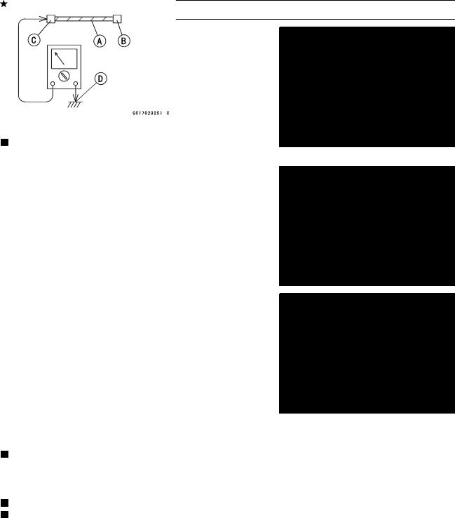
○If both ends of a harness [A] are far apart, ground [B] the one end [C], using a jumper lead [D] and check the continuity between the end [E] and the ground [F]. This enables to check a long harness for continuity. If the harness is open, repair or replace the harness.
○When checking a harness [A] for short circuit, open one end [B] and check the continuity between the other end [C] and ground [D]. If there is continuity, the harness has a short circuit to ground, and it must be repaired or replaced.
•Narrow down suspicious locations by repeating the continuity tests from the ECU connectors.
If no abnormality is found in the wiring or connectors, the DFI parts are the next likely suspects. Check the part, starting with input and output voltages. However, there is no way to check the ECU itself.
If an abnormality is found, replace the affected DFI part. If no abnormality is found in the wiring, connectors, and DFI parts, replace the ECU.
Lead Color Codes: |
|
|
○ |
|
|
BK: Black |
G: Green |
P: Pink |
BL: Blue |
GY: Gray |
PU: Purple |
BR: Brown |
LB: Light blue |
R: Red |
CH: Chocolate |
LG: Light green |
W: White |
DG: Dark green |
O: Orange |
Y: Yellow |

3-20 FUEL SYSTEM (DFI)
Troubleshooting the DFI System
○There are two ways to inspect the DFI system. One is voltage Check Method and the other is Resistance Check Method.
(Voltage Check Method)
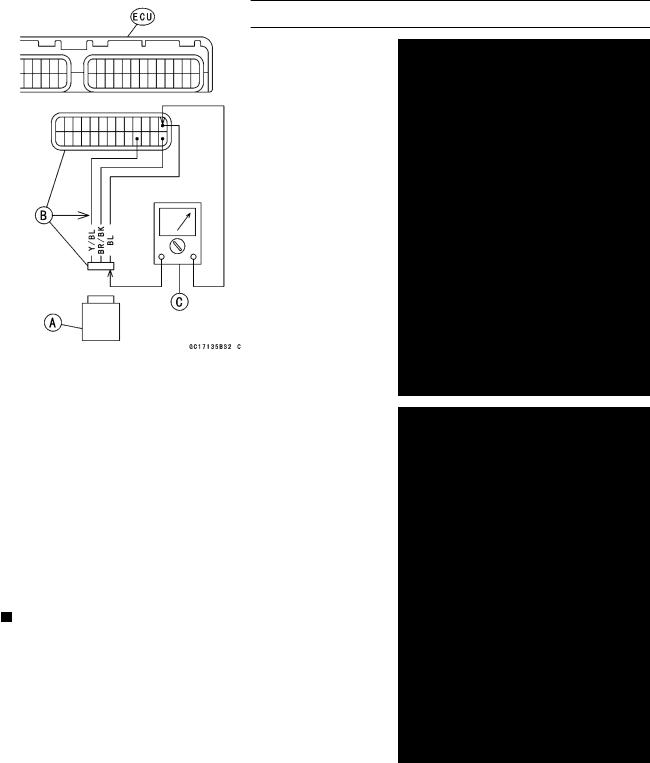
○This method is conducted by measuring the input voltage [B] to a sensor [A] first, and then the output voltage [C] from the sensor.
•Sometimes this method can detect a fault of the ECU. Refer to each sensor inspection section for detail in this
•chapter.
Use a fully charged battery and a digital meter [D] which can be read two decimal places voltage or resistance.
(Resistance Check Method)
○This method is simple. No need for a fully charged battery and the needle adapter. Just do the following especially
•when a sensor [A] is suspect.
•Turn the ignition SW OFF and disconnect the connectors. Inspect the sensor resistance, using a digital meter (see
•each sensor inspection in this chapter).
Inspect the wiring and connectors [B] for continuity, using the hand tester [C] (analog tester) rather than a digital meter.
Special Tool - Hand Tester: 57001–1394
If the sensor, the wiring and connections are good, inspect the ECU for its ground and power supply (see this chapter). If the ground and power supply are good, the ECU is suspect. Replace the ECU.