
- •LIST OF ABBREVIATIONS
- •New Ignition Interlock Sidestand System
- •Current Ignition Interlock Sidestand System
- •Materials of Semi-Conductor and Emitting Color
- •Units of Mass:
- •Units of Volume:
- •Units of Force:
- •Units of Length:
- •Units of Torque:
- •Units of Pressure:
- •Units of Speed:
- •Units of Power:
- •Periodic Inspection:
- •Periodic Replacement Parts:
- •Basic Torque for General Fasteners
- •Throttle Grip Free Play
- •Idle Speed
- •Engine Vacuum
- •Water and Coolant Mixture Ratio (when shipping)
- •Valve Clearance
- •Clutch Lever Free Play
- •Engine Oil
- •Tread Depth
- •Air Pressure (when cold)
- •Chain Slack
- •Drive Chain 20-link Length
- •Standard Chain
- •Pad Lining Thickness
- •Sample Diagnosis Sheet
- •Poor Running at Low Speed
- •Poor Running or No Power at High Speed:
- •Wiring Connection
- •Idle Speed
- •Wiring Connection
- •Main Throttle Sensor Resistance
- •Inlet Air Pressure Sensor Output Voltage
- •Inlet Air Temperature Sensor Output Voltage
- •Water Temperature Sensor Output Voltage
- •Atmospheric Pressure Sensor Input Voltage
- •Output Voltage at Sensor
- •Wiring Connection
- •Throttle Sensor Resistance
- •Stick Coil Input Voltage at ECU
- •Input Voltage at ECU
- •Subthrottle Valve Actuator Resistance
- •Subthrottle Valve Actuator Input Voltage
- •Input Voltage at Actuator
- •FI Indicator LED Light Check
- •ECU Grounding Inspection
- •ECU Power Source Inspection
- •Testing Relay
- •Fuel Pressure
- •Fuel Pressure (idling)
- •Amount of Fuel Flow
- •Testing Relay
- •Injector Power Source Voltage at ECU
- •Output Voltage at Injector Connector
- •Injector Wiring Inspection
- •Choke Lever Free Play
- •Radiator Cap Relief Pressure
- •Thermostat Valve Opening Temperature
- •Camshaft Journal, Camshaft Cap Clearance
- •Camshaft Journal Diameter
- •Camshaft Runout
- •Cylinder Compression
- •Cylinder Head Warp
- •Valve/Valve Guide Clearance (Wobble Method)
- •Valve Seating Surface Outside Diameter
- •Valve Seating Surface Width
- •Cylinder Inside Diameter
- •Piston Diameter
- •Piston Ring/Groove Clearance
- •Piston Ring Groove Width
- •Piston Ring Thickness
- •Piston Ring End Gap
- •Clutch Plate Assembly
- •Friction Plate Thickness
- •Friction and Steel Plate Warp
- •Clutch Spring Free Length
- •Oil Pressure
- •Connecting Rod Bend
- •Connecting Rod Twist
- •Connecting Rod Big End Side Clearance
- •Crankpin Diameter
- •Crankpin Diameter Marks
- •Connecting Rod Big End Inside Diameter Marks
- •Crankshaft Side Clearance
- •Crankshaft Runout
- •Crankshaft Main Journal Diameter
- •Crankshaft Main Journal Diameter Marks
- •Crankcase Main Bearing Inside Diameter Marks
- •Shift Fork Ear Thickness
- •Gear Groove Width
- •Shift Fork Guide Pin Diameter
- •Shift Drum Groove Width
- •Rim Runout
- •Axle Runout/100 mm (3.94 in.)
- •Balance Weight
- •Link Pin Outside Diameter
- •Link Plates Outside Width
- •Rear Sprocket Warp
- •Pedal Position
- •Front Disc Thickness
- •Rear Disc Thickness
- •Disc Runout
- •Oil Level (fully compressed, without spring)
- •Fork Spring Free Length
- •Rebound Damping Adjustment
- •Spring Preload Setting
- •Spring Preload Adjustment
- •Table 1 Alternator Output Voltage
- •Table 2 Stator Coil Resistance
- •Rectifier Circuit Inspection
- •Charging Voltage
- •Crankshaft Sensor Peak Voltage
- •Connections:
- •Camshaft Position Sensor Peak Voltage
- •Ignition Coil Winding Resistance
- •Primary Lead Connection
- •Connection:
- •Condition:
- •Starter Motor Brush Length
- •Commutator Diameter
- •Testing Relay
- •Testing Turn Signal Relay
- •Water Temperature Sensor
- •Fuel Level Sensor Resistance
- •Connections:
- •Fuse Circuit Inspection
- •Relay Circuit Inspection (with the battery disconnected)
- •Relay Circuit Inspection (with the battery connected)
- •Diode Circuit Inspection
- •Foreword
- •General Information
- •Battery Ground
- •Edges of Parts
- •Solvent
- •Cleaning vehicle before disassembly
- •Arrangement and Cleaning of Removed Parts
- •Storage of Removed Parts
- •Inspection
- •Replacement Parts
- •Assembly Order
- •Tightening Sequence
- •Tightening Torque
- •Force
- •Gasket, O-ring
- •Liquid Gasket, Locking Agent
- •Press
- •Ball Bearing and Needle Bearing
- •Oil Seal, Grease Seal
- •Circlips, Cotter Pins
- •Lubrication
- •Direction of Engine Rotation
- •Electrical Wires
- •ZR750–J1 Left Side View:
- •ZR750–J1 Right Side View:
- •Subthrottle Control System
- •Outline
- •Outline
- •Due Position of LED Installation
- •Honeycomb Type Catalytic Converter
- •Prefixes for Units:
- •Units of Temperature:
- •Periodic Maintenance
- •Steering Stem Nut Wrench:
- •Fuel System (DFI)
- •Fuel Hose and Connection Inspection
- •Throttle Control System Inspection
- •Engine Vacuum Synchronization Inspection
- •Air Cleaner Element Cleaning
- •Cooling System
- •Radiator Hose and Connection Inspection
- •Coolant Change
- •Engine Top End
- •Valve Clearance Inspection
- •Clutch
- •Engine Lubrication System
- •Engine Oil Change
- •Wheels/Tires
- •Tire Wear Inspection
- •Air Pressure Inspection
- •Final Drive
- •Drive Chain Slack Inspection
- •Brakes
- •Rear Brake Light Switch Connections:
- •Caliper Fluid Seal Damage
- •Brake Line Bleeding
- •Suspension
- •Steering
- •Steering Adjustment
- •Electrical System
- •General Lubrication
- •Lubrication
- •Nut, Bolt, and Fastener Tightness
- •Fuel System (DFI)
- •Terminal Names
- •Part Name
- •Oil Pressure Gauge:
- •DFI Servicing Precautions
- •Outline
- •Outline
- •DFI Diagnosis Flow Chart
- •Inquiries to Rider
- •DFI System Troubleshooting Guide
- •Self-diagnosis Outline
- •Self-diagnosis Procedures
- •Service Code Clearing Procedures
- •How to Read Service Codes
- •How to Erase Service Codes
- •Service Code Table
- •Notes:
- •Backups
- •Backups
- •Main Throttle Sensor Removal/Adjustment
- •Input Voltage Inspection
- •Resistance Inspection
- •CAUTION
- •Removal
- •Installation
- •Input Voltage Inspection
- •Output Voltage Inspection
- •Removal/Installation
- •Output Voltage Inspection
- •Removal/Installation
- •Output Voltage Inspection
- •CAUTION
- •Removal
- •Input Voltage Inspection
- •Crankshaft Sensor Inspection
- •Camshaft Position Sensor Removal/Installation
- •Camshaft Position Sensor Inspection
- •Input Voltage Inspection
- •Removal
- •Installation
- •Inspection
- •Subthrottle Sensor Removal/Adjustment
- •Input Voltage Inspection
- •Removal/Installation
- •Input Voltage Inspection
- •Subthrottle Valve Actuator Removal
- •Audible Inspection
- •Input Voltage Inspection
- •Inspection Flow Chart
- •CAUTION
- •ECU Power Source Circuit
- •ECU Fuse Installation
- •ECU Main Relay Removal
- •Fuel Pressure Inspection
- •Fuel Flow Rate Inspection
- •Fuel Pump Removal
- •Operation Inspection
- •Operating Voltage Inspection
- •Pressure Regulator Removal
- •Pump Screen, Fuel Filter Cleaning
- •Fuel Pump Relay Removal
- •Removal/Installation
- •Choke Lever Operation
- •Throttle Body Assy Removal
- •Throttle Body Assy Disassembly
- •Throttle Body Assy Assembly
- •Air Cleaner Oil Draining
- •Fuel Tank Removal
- •Fuel Tank Cleaning
- •Cooling System
- •Bearing Driver:
- •Coolant Level Inspection
- •Cooling System Flushing
- •Water Pump Housing Disassembly
- •Water Pump Housing Assembly
- •Radiator and Radiator Fan Removal
- •CAUTION
- •Engine Top End
- •Exhaust System
- •Compression Gauge:
- •Camshaft Chain Tensioner Removal
- •Cylinder Compression Measurement
- •Cylinder Head Installation
- •Valve Guide Installation
- •Seat Cutter Operation Care:
- •Cylinder Installation
- •WARNING
- •Clutch
- •Clutch Holder:
- •Clutch Lever Adjustment
- •Release Shaft Removal
- •Engine Lubrication System
- •WARNING
- •Oil Pressure Measurement
- •Engine Removal/Installation
- •Crankshaft/Transmission
- •Bearing Puller:
- •Crankcase Splitting
- •Crankcase Assembly
- •Crankshaft Installation
- •Connecting Rod Installation
- •Wheels/Tires
- •Bearing Driver Set:
- •Front Wheel Installation
- •Axle Inspection
- •Tire Installation
- •Tire Repair
- •Hub Bearing Inspection
- •Final Drive
- •Bearing Driver Set:
- •Coupling Bearing Inspection
- •Brakes
- •Jack:
- •Brake Lever Position Adjustment
- •Brake Pedal Position Adjustment
- •Caliper Holder Shaft Wear
- •Rear Master Cylinder Disassembly
- •Brake Hose Removal/Installation
- •Suspension
- •Fork Cylinder Holder Handle:
- •Swingarm Installation
- •Swingarm Bearing, Sleeve Inspection
- •Steering
- •Steering Stem Nut Wrench:
- •Frame
- •Electrical System
- •Rotor Puller, M16/M18/M20/M22 × 1.5 :
- •Battery Removal
- •Initial Charge
- •Precautions
- •Alternator Inspection
- •Charging System Circuit
- •WARNING
- •Special Tool -
- •Crankshaft Sensor Peak Voltage Inspection
- •Stick Coil (Ignition Coil together with Spark Plug Cap) Removal
- •Stick Coil Primary Peak Voltage
- •IC Igniter Inspection
- •Ignition System Circuit
- •Starter Motor Removal
- •Starter Motor Installation
- •Electric Starter Circuit
- •Headlight/Tail Light Circuit (CA, AS)
- •Headlight/Tail Light Circuit (Other than CA, AS)
- •Turn Signal Light Circuit
- •Turn Signal Light Bulb Replacement
- •Radiator Fan Circuit
- •Electronic Combination Meter Unit Inspection
- •Meter Circuit
- •Rear Brake Light Switch Connections
- •Side Stand Switch Connections
- •Neutral Switch Connections
- •Oil Pressure Switch Connections*
- •Special Tool -
- •Junction Box Internal Circuit
- •30 A Main Fuse Removal
- •15 A ECU Fuse Removal
- •Appendix
- •NOTE
- •Starter motor not rotating:
- •No fuel flow:
- •Engine flooded:
- •No spark; spark weak:
- •Fuel/air mixture incorrect:
- •Compression Low:
- •Poor Running at Low Speed:
- •Spark weak:
- •Fuel/air mixture incorrect:
- •Compression low:
- •Other:
- •Poor Running or No Power at High Speed:
- •Firing incorrect:
- •Fuel/air mixture incorrect:
- •Compression low:
- •Knocking:
- •Miscellaneous:
- •Overheating:
- •Firing incorrect:
- •Muffler overheating:
- •Fuel/air mixture incorrect:
- •Compression high:
- •Engine load faulty:
- •Lubrication inadequate:
- •Gauge incorrect:
- •Coolant incorrect:
- •Cooling system component incorrect:
- •Over Cooling:
- •Gauge incorrect:
- •Cooling system component incorrect:
- •Clutch Operation Faulty:
- •Clutch slipping:
- •Clutch not disengaging properly:
- •Gear Shifting Faulty:
- •Jumps out of gear:
- •Overshifts:
- •Abnormal Engine Noise:
- •Knocking:
- •Piston slap:
- •Valve noise:
- •Other noise:
- •Abnormal Drive Train Noise:
- •Clutch noise:
- •Transmission noise:
- •Drive line noise:
- •Abnormal Frame Noise:
- •Front fork noise:
- •Rear shock absorber noise:
- •Disc brake noise:
- •Other noise:
- •Oil Pressure Warning Light Goes On:
- •Exhaust Smokes Excessively:
- •White smoke:
- •Black smoke:
- •Brown smoke:
- •Handlebar hard to turn:
- •Handlebar shakes or excessively vibrates:
- •Handlebar pulls to one side:
- •Shock absorption unsatisfactory:
- •Battery Trouble:
- •Battery discharged:
- •Battery overcharged:

ELECTRICAL SYSTEM 16-43
Ignition System
Stick Coil (Ignition Coil together with Spark Plug Cap)
Inspection•
•Remove the stick coils (see this chapter).
Measure the primary winding resistance [A] as follows. ○Connect the hand tester between the coil terminals. ○•Set the tester to the × 1 Ω range, and read the tester.
Measure the secondary winding resistance [B] as follows. ○Connect the tester between the plug terminal and (–) coil
terminal.
○Set the tester to the × 1 kΩ range and read the tester.
Ignition Coil Winding Resistance |
|
|
Primary Windings: |
1.04 |
1.56 Ω |
Secondary Windings: |
10.8 |
16.2 kΩ |
If the tester does not read as specified, replace the coil.
Stick Coil Primary Peak Voltage
NOTE
○Be sure the battery is fully charged.
•Remove the stick coils (see this chapter), but do not re-
•move the spark plugs.
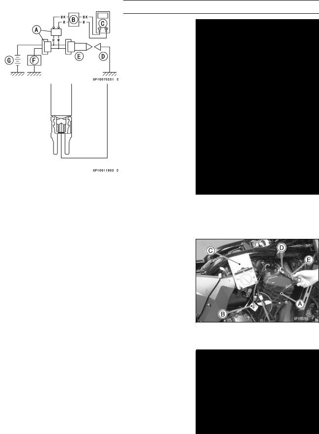
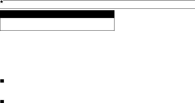
Measure the primary peak voltage as follows. ○Connect a commercially peak voltage adapter [B] into the
hand tester [C] which is set to the x 250 V DC range. ○Connect the adapter to the lead wire-peak voltage adapter [A] which is connected between the stick coil
connector and stick coil.
○Install the new spark plug [D] into each stick coil [E], and ground them onto the engine.
ECU [F]
Battery [G]
Recommended ToolPeak Voltage Adapter
Type: KEK-54-9-B
Brand: KOWA SEIKI
Special Tools - Hand Tester: 57001–1394
Lead Wire-Peak Voltage Adapter:
57001–1449
Primary Lead Connection
Adapter (R, +) to lead wire-peak voltage adapter (W)
Adapter (BK, –) to lead wire-peak voltage adapter (R)

16-44 ELECTRICAL SYSTEM
Ignition System
WARNING
To avoid extremely high voltage shocks, do not touch the spark plugs or tester connections.
•Turn the ignition switch and the engine stop switch ON.
•Pushing the starter button, turn the engine 4 5 seconds with the transmission in neutral to measure the primary
•peak voltage.
Repeat the measurements 5 times for one stick coil.
Stick Coil Primary Peak Voltage Standard: 88 V or more
•Repeat the test for the other stick coil.
If the reading is less than the specified value, check the following.
Stick Coils (see Stick Coil Inspection)
Crankshaft Sensor (see Crankshaft Sensor Inspection) If the stick coils, and crankshaft sensor are normal, check the ECU (see Fuel System (DFI) chapter).
Spark• Plug Removal
Refer to the Electrical System in the Periodic Maintenance chapter.
Spark• Plug Installation
Refer to the Electrical System in the Periodic Maintenance chapter.
Spark• Plug Inspection
Refer to the Electrical System in the Periodic Maintenance chapter.
Spark• Plug Gap Inspection
Refer to the Electrical System in the Periodic Maintenance chapter.

ELECTRICAL SYSTEM 16-45
Ignition System
Interlock• Operation Inspection
Remove:
Seats (see Frame chapter)
Junction Box (see this chapter)
○Do not disconnect the connectors.
1st• Check
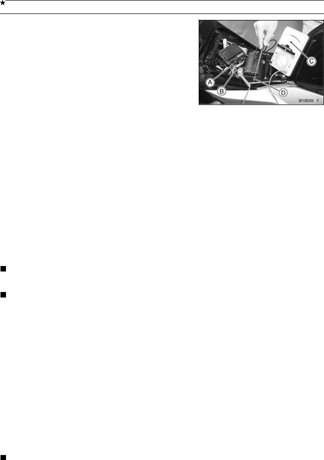
Measure the terminal voltage of the G/BK lead in the junction box connector [A] in accordance with the following procedure.
○Insert the needle adapter [B] in the Green/Black lead terminal.
○Set the tester [C] to the 25 V DC range, connect it to the needle adapter and frame ground [D].
Connection:
Tester (+) Terminal → G/BK Lead Terminal
Tester (–) Terminal → Frame Ground
Condition:
Transmission Gear → 1st Position Clutch Lever → Release or Pulled In Side Stand → Down
Special Tool - Needle Adapter Set: 57001–1457
○Turn the ignition switch on. ○Read the voltage.
Interlock Operation Voltage Standard: 4 V or more
If the voltage is lower than the standard, inspect the side stand switch, starter lockout switch, and junction box. And their parts are normality, replace the ECU.
If the voltage is standard, push the starter button to check as follows.
○If the starter motor does not turn, the ECU is good, and check the starter system circuit.
○If the starter motor turned, ECU is defective. Replace the ECU.
2nd Check
•Raise the rear wheel off the ground with a stand. Inspect the engine for its secure stop after the following
•operations are completed.
Run the engine to the following conditions.
•Setstop.the side stand on the ground, then the engine will If whichever may not be stopped, inspect the starter lockout switch, side stand switch and junction box.
If their parts are normality, replace the ECU.