

Добавил:
Upload
Опубликованный материал нарушает ваши авторские права? Сообщите нам.
Вуз:
Предмет:
Файл:Kawasaki Z750 03 Service Manual ENG By Mosue.pdf
Источник:
X
- •LIST OF ABBREVIATIONS
- •New Ignition Interlock Sidestand System
- •Current Ignition Interlock Sidestand System
- •Materials of Semi-Conductor and Emitting Color
- •Units of Mass:
- •Units of Volume:
- •Units of Force:
- •Units of Length:
- •Units of Torque:
- •Units of Pressure:
- •Units of Speed:
- •Units of Power:
- •Periodic Inspection:
- •Periodic Replacement Parts:
- •Basic Torque for General Fasteners
- •Throttle Grip Free Play
- •Idle Speed
- •Engine Vacuum
- •Water and Coolant Mixture Ratio (when shipping)
- •Valve Clearance
- •Clutch Lever Free Play
- •Engine Oil
- •Tread Depth
- •Air Pressure (when cold)
- •Chain Slack
- •Drive Chain 20-link Length
- •Standard Chain
- •Pad Lining Thickness
- •Sample Diagnosis Sheet
- •Poor Running at Low Speed
- •Poor Running or No Power at High Speed:
- •Wiring Connection
- •Idle Speed
- •Wiring Connection
- •Main Throttle Sensor Resistance
- •Inlet Air Pressure Sensor Output Voltage
- •Inlet Air Temperature Sensor Output Voltage
- •Water Temperature Sensor Output Voltage
- •Atmospheric Pressure Sensor Input Voltage
- •Output Voltage at Sensor
- •Wiring Connection
- •Wiring Connection
- •Throttle Sensor Resistance
- •Stick Coil Input Voltage at ECU
- •Input Voltage at ECU
- •Subthrottle Valve Actuator Resistance
- •Subthrottle Valve Actuator Input Voltage
- •Input Voltage at Actuator
- •FI Indicator LED Light Check
- •ECU Grounding Inspection
- •ECU Power Source Inspection
- •Testing Relay
- •Fuel Pressure
- •Fuel Pressure (idling)
- •Amount of Fuel Flow
- •Testing Relay
- •Injector Power Source Voltage at ECU
- •Output Voltage at Injector Connector
- •Injector Wiring Inspection
- •Choke Lever Free Play
- •Radiator Cap Relief Pressure
- •Thermostat Valve Opening Temperature
- •Camshaft Journal, Camshaft Cap Clearance
- •Camshaft Journal Diameter
- •Camshaft Runout
- •Cylinder Compression
- •Cylinder Head Warp
- •Valve/Valve Guide Clearance (Wobble Method)
- •Valve Seating Surface Outside Diameter
- •Valve Seating Surface Width
- •Cylinder Inside Diameter
- •Piston Diameter
- •Piston Ring/Groove Clearance
- •Piston Ring Groove Width
- •Piston Ring Thickness
- •Piston Ring End Gap
- •Clutch Plate Assembly
- •Friction Plate Thickness
- •Friction and Steel Plate Warp
- •Clutch Spring Free Length
- •Oil Pressure
- •Connecting Rod Bend
- •Connecting Rod Twist
- •Connecting Rod Big End Side Clearance
- •Crankpin Diameter
- •Crankpin Diameter Marks
- •Connecting Rod Big End Inside Diameter Marks
- •Crankshaft Side Clearance
- •Crankshaft Runout
- •Crankshaft Main Journal Diameter
- •Crankshaft Main Journal Diameter Marks
- •Crankcase Main Bearing Inside Diameter Marks
- •Shift Fork Ear Thickness
- •Gear Groove Width
- •Shift Fork Guide Pin Diameter
- •Shift Drum Groove Width
- •Rim Runout
- •Axle Runout/100 mm (3.94 in.)
- •Balance Weight
- •Link Pin Outside Diameter
- •Link Plates Outside Width
- •Rear Sprocket Warp
- •Pedal Position
- •Front Disc Thickness
- •Rear Disc Thickness
- •Disc Runout
- •Oil Level (fully compressed, without spring)
- •Fork Spring Free Length
- •Rebound Damping Adjustment
- •Spring Preload Setting
- •Spring Preload Adjustment
- •Table 1 Alternator Output Voltage
- •Table 2 Stator Coil Resistance
- •Rectifier Circuit Inspection
- •Charging Voltage
- •Crankshaft Sensor Peak Voltage
- •Connections:
- •Camshaft Position Sensor Peak Voltage
- •Ignition Coil Winding Resistance
- •Primary Lead Connection
- •Connection:
- •Condition:
- •Starter Motor Brush Length
- •Commutator Diameter
- •Testing Relay
- •Testing Turn Signal Relay
- •Water Temperature Sensor
- •Fuel Level Sensor Resistance
- •Connections:
- •Fuse Circuit Inspection
- •Relay Circuit Inspection (with the battery disconnected)
- •Relay Circuit Inspection (with the battery connected)
- •Diode Circuit Inspection
- •Foreword
- •General Information
- •Battery Ground
- •Edges of Parts
- •Solvent
- •Cleaning vehicle before disassembly
- •Arrangement and Cleaning of Removed Parts
- •Storage of Removed Parts
- •Inspection
- •Replacement Parts
- •Assembly Order
- •Tightening Sequence
- •Tightening Torque
- •Force
- •Gasket, O-ring
- •Liquid Gasket, Locking Agent
- •Press
- •Ball Bearing and Needle Bearing
- •Oil Seal, Grease Seal
- •Circlips, Cotter Pins
- •Lubrication
- •Direction of Engine Rotation
- •Electrical Wires
- •ZR750–J1 Left Side View:
- •ZR750–J1 Right Side View:
- •Subthrottle Control System
- •Outline
- •Outline
- •Due Position of LED Installation
- •Honeycomb Type Catalytic Converter
- •Prefixes for Units:
- •Units of Temperature:
- •Periodic Maintenance
- •Steering Stem Nut Wrench:
- •Fuel System (DFI)
- •Fuel Hose and Connection Inspection
- •Throttle Control System Inspection
- •Engine Vacuum Synchronization Inspection
- •Air Cleaner Element Cleaning
- •Cooling System
- •Radiator Hose and Connection Inspection
- •Coolant Change
- •Engine Top End
- •Valve Clearance Inspection
- •Clutch
- •Engine Lubrication System
- •Engine Oil Change
- •Wheels/Tires
- •Tire Wear Inspection
- •Air Pressure Inspection
- •Final Drive
- •Drive Chain Slack Inspection
- •Brakes
- •Rear Brake Light Switch Connections:
- •Caliper Fluid Seal Damage
- •Brake Line Bleeding
- •Suspension
- •Steering
- •Steering Adjustment
- •Electrical System
- •General Lubrication
- •Lubrication
- •Nut, Bolt, and Fastener Tightness
- •Fuel System (DFI)
- •Terminal Names
- •Part Name
- •Oil Pressure Gauge:
- •DFI Servicing Precautions
- •Outline
- •Outline
- •DFI Diagnosis Flow Chart
- •Inquiries to Rider
- •Inquiries to Rider
- •DFI System Troubleshooting Guide
- •Self-diagnosis Outline
- •Self-diagnosis Outline
- •Self-diagnosis Procedures
- •Self-diagnosis Procedures
- •Service Code Clearing Procedures
- •How to Read Service Codes
- •How to Read Service Codes
- •How to Erase Service Codes
- •How to Erase Service Codes
- •Service Code Table
- •Service Code Table
- •Notes:
- •Backups
- •Backups
- •Main Throttle Sensor Removal/Adjustment
- •Input Voltage Inspection
- •Resistance Inspection
- •CAUTION
- •Removal
- •Installation
- •Input Voltage Inspection
- •Output Voltage Inspection
- •Removal/Installation
- •Output Voltage Inspection
- •Removal/Installation
- •Output Voltage Inspection
- •CAUTION
- •Removal
- •Input Voltage Inspection
- •Crankshaft Sensor Inspection
- •Camshaft Position Sensor Removal/Installation
- •Camshaft Position Sensor Inspection
- •Input Voltage Inspection
- •Removal
- •Installation
- •Inspection
- •Subthrottle Sensor Removal/Adjustment
- •Input Voltage Inspection
- •Removal/Installation
- •Input Voltage Inspection
- •Subthrottle Valve Actuator Removal
- •Audible Inspection
- •Input Voltage Inspection
- •Inspection Flow Chart
- •CAUTION
- •ECU Power Source Circuit
- •ECU Fuse Installation
- •ECU Main Relay Removal
- •Fuel Pressure Inspection
- •Fuel Flow Rate Inspection
- •Fuel Pump Removal
- •Operation Inspection
- •Operating Voltage Inspection
- •Pressure Regulator Removal
- •Pump Screen, Fuel Filter Cleaning
- •Fuel Pump Relay Removal
- •Removal/Installation
- •Choke Lever Operation
- •Throttle Body Assy Removal
- •Throttle Body Assy Disassembly
- •Throttle Body Assy Assembly
- •Air Cleaner Oil Draining
- •Fuel Tank Removal
- •Fuel Tank Cleaning
- •Cooling System
- •Bearing Driver:
- •Coolant Level Inspection
- •Cooling System Flushing
- •Water Pump Housing Disassembly
- •Water Pump Housing Assembly
- •Radiator and Radiator Fan Removal
- •CAUTION
- •Engine Top End
- •Exhaust System
- •Compression Gauge:
- •Camshaft Chain Tensioner Removal
- •Cylinder Compression Measurement
- •Cylinder Head Installation
- •Valve Guide Installation
- •Seat Cutter Operation Care:
- •Cylinder Installation
- •WARNING
- •Clutch
- •Clutch Holder:
- •Clutch Lever Adjustment
- •Release Shaft Removal
- •Engine Lubrication System
- •WARNING
- •Oil Pressure Measurement
- •Engine Removal/Installation
- •Crankshaft/Transmission
- •Bearing Puller:
- •Crankcase Splitting
- •Crankcase Assembly
- •Crankshaft Installation
- •Connecting Rod Installation
- •Wheels/Tires
- •Bearing Driver Set:
- •Front Wheel Installation
- •Axle Inspection
- •Tire Installation
- •Tire Repair
- •Hub Bearing Inspection
- •Final Drive
- •Bearing Driver Set:
- •Coupling Bearing Inspection
- •Brakes
- •Jack:
- •Brake Lever Position Adjustment
- •Brake Pedal Position Adjustment
- •Caliper Holder Shaft Wear
- •Rear Master Cylinder Disassembly
- •Brake Hose Removal/Installation
- •Suspension
- •Fork Cylinder Holder Handle:
- •Swingarm Installation
- •Swingarm Bearing, Sleeve Inspection
- •Steering
- •Steering Stem Nut Wrench:
- •Frame
- •Electrical System
- •Rotor Puller, M16/M18/M20/M22 × 1.5 :
- •Battery Removal
- •Initial Charge
- •Precautions
- •Alternator Inspection
- •Charging System Circuit
- •WARNING
- •Special Tool -
- •Crankshaft Sensor Peak Voltage Inspection
- •Stick Coil (Ignition Coil together with Spark Plug Cap) Removal
- •Stick Coil Primary Peak Voltage
- •IC Igniter Inspection
- •Ignition System Circuit
- •Starter Motor Removal
- •Starter Motor Installation
- •Electric Starter Circuit
- •Headlight/Tail Light Circuit (CA, AS)
- •Headlight/Tail Light Circuit (Other than CA, AS)
- •Turn Signal Light Circuit
- •Turn Signal Light Bulb Replacement
- •Radiator Fan Circuit
- •Electronic Combination Meter Unit Inspection
- •Meter Circuit
- •Rear Brake Light Switch Connections
- •Side Stand Switch Connections
- •Neutral Switch Connections
- •Oil Pressure Switch Connections*
- •Special Tool -
- •Junction Box Internal Circuit
- •30 A Main Fuse Removal
- •15 A ECU Fuse Removal
- •Appendix
- •NOTE
- •Starter motor not rotating:
- •No fuel flow:
- •Engine flooded:
- •No spark; spark weak:
- •Fuel/air mixture incorrect:
- •Compression Low:
- •Poor Running at Low Speed:
- •Spark weak:
- •Fuel/air mixture incorrect:
- •Compression low:
- •Other:
- •Poor Running or No Power at High Speed:
- •Firing incorrect:
- •Fuel/air mixture incorrect:
- •Compression low:
- •Knocking:
- •Miscellaneous:
- •Overheating:
- •Firing incorrect:
- •Muffler overheating:
- •Fuel/air mixture incorrect:
- •Compression high:
- •Engine load faulty:
- •Lubrication inadequate:
- •Gauge incorrect:
- •Coolant incorrect:
- •Cooling system component incorrect:
- •Over Cooling:
- •Gauge incorrect:
- •Cooling system component incorrect:
- •Clutch Operation Faulty:
- •Clutch slipping:
- •Clutch not disengaging properly:
- •Gear Shifting Faulty:
- •Jumps out of gear:
- •Overshifts:
- •Abnormal Engine Noise:
- •Knocking:
- •Piston slap:
- •Valve noise:
- •Other noise:
- •Abnormal Drive Train Noise:
- •Clutch noise:
- •Transmission noise:
- •Drive line noise:
- •Abnormal Frame Noise:
- •Front fork noise:
- •Rear shock absorber noise:
- •Disc brake noise:
- •Other noise:
- •Oil Pressure Warning Light Goes On:
- •Exhaust Smokes Excessively:
- •White smoke:
- •Black smoke:
- •Brown smoke:
- •Handlebar hard to turn:
- •Handlebar shakes or excessively vibrates:
- •Handlebar pulls to one side:
- •Shock absorption unsatisfactory:
- •Battery Trouble:
- •Battery discharged:
- •Battery overcharged:
16-36 ELECTRICAL SYSTEM
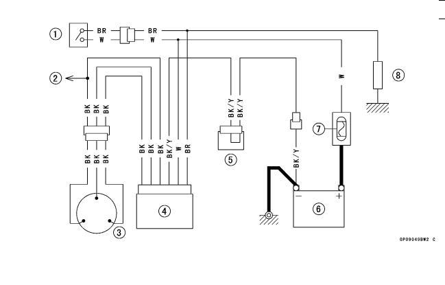
Charging System
Charging System Circuit
|
|
|
|
|
|
|
1. |
Ignition Switch |
4. |
Regulator/Rectifier |
7. |
Main Fuse 30 A |
|
2. |
To Starter Circuit Relay |
5. |
Joint Connector C |
8. |
Load |
|
3. |
Alternator |
6. |
Battery 12 V 8 Ah |
|
|
|
Соседние файлы в предмете [НЕСОРТИРОВАННОЕ]