

3G Evolution. HSPA and LTE for Mobile Broadband
.pdfHigh data rates in mobile communication |
33 |
Minimum required Eb /N0 (dB)
Figure 3.1
20 |
|
|
|
Power-limited |
Bandwidth-limited |
15 |
region |
region |
|
|
10
5
0
5
0.1 |
1 |
10 |
Bandwidth utilization g
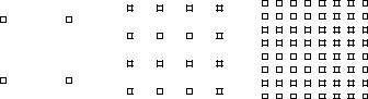
Minimum required Eb/N0 at the receiver as a function of bandwidth utilization.
3.1.1 High data rates in noise-limited scenarios
From the discussion above, some basic conclusions can be drawn regarding the provisioning of higher data rates in a mobile-communication system when noise is the main source of radio-link impairment (a noise-limited scenario):
•The data rates that can be provided in such scenarios are always limited by the available received signal power or, in the general case, the received signal- power-to-noise-power ratio. Furthermore, any increase of the achievable data rate within a given bandwidth will require at least the same relative increase of the received signal power. At the same time, if sufficient received signal power can be made available, basically any data rate can, at least in theory, be provided within a given limited bandwidth.
•In case of low-bandwidth utilization, i.e. as long as the radio-link data rate is substantially lower than the available bandwidth, any further increase of the data rate requires approximately the same relative increase in the received signal power. This can be referred to as power-limited operation (in contrast to bandwidth-limited operation, see below) as, in this case, an increase in the available bandwidth does not substantially impact what received signal power is required for a certain data rate.
•On the other hand, in case of high-bandwidth utilization, i.e. in case of data rates in the same order as or exceeding the available bandwidth, any further increase in the data rate requires a much larger relative increase in the received signal power unless the bandwidth is increased in proportion to the increase in data rate. This can be referred to bandwidth-limited operation as, in this case, an increase in the bandwidth will reduce the received signal power required for
a certain data rate.
34 |
3G Evolution: HSPA and LTE for Mobile Broadband |
Thus, to make efficient use of the available received signal power or, in the general case, the available signal-to-noise ratio, the transmission bandwidth should at least be of the same order as the data rates to be provided.
Assuming a constant transmit power, the received signal power can always be increased by reducing the distance between the transmitter and the receiver, thereby reducing the attenuation of the signal as it propagates from the transmitter to the receiver. Thus, in a noise-limited scenario it is at least in theory always possible to increase the achievable data rates, assuming that one is prepared to accept a reduction in the transmitter/receiver distance, that is a reduced range. In a mobilecommunication system this would correspond to a reduced cell size and thus the need for more cell sites to cover the same overall area. Especially, providing data rates in the same order as or larger than the available bandwidth, i.e. with a high-bandwidth utilization, would require a significant cell-size reduction. Alternatively, one has to accept that the high data rates are only available for mobile terminals in the center of the cell, i.e. not over the entire cell area.
Another means to increase the overall received signal power for a given transmit power is the use of additional antennas at the receiver side, also known as receive-antenna diversity. Multiple receive antennas can be applied at the base station (that is for the uplink) or at the mobile terminal (that is for the downlink). By proper combining of the signals received at the different antennas, the signal- to-noise ratio after the antenna combining can be increased in proportion to the number of receive antennas, thereby allowing for higher data rates for a given transmitter/receiver distance.
Multiple antennas can also be applied at the transmitter side, typically at the base station, and be used to focus a given total transmit power in the direction of the receiver, i.e. toward the target mobile terminal. This will increase the received signal power and thus, once again, allow for higher data rates for a given transmitter/receiver distance.
However, providing higher data rates by the use of multiple transmit or receive antennas is only efficient up to a certain level, i.e. as long as the data rates are power limited rather than bandwidth limited. Beyond this point, the achievable data rates start to saturate and any further increase in the number of transmit or receive antennas, although leading to a correspondingly improved signal-to-noise ratio at the receiver, will only provide a marginal increase in the achievable data rates. This saturation in achievable data rates can be avoided though, by the use of multiple antennas at both the transmitter and the receiver, enabling what can be referred to as spatial multiplexing, often also referred to as MIMO (MultipleInput Multiple-Output). Different types of multi-antenna techniques, including spatial multiplexing, will be discussed in more detail in Chapter 6. Multi-antenna
High data rates in mobile communication |
35 |
techniques for the specific case of HSPA and LTE are discussed in Part III and IV of this book, respectively.
An alternative to increasing the received signal power is to reduce the noise power, or more exactly the noise power density, at the receiver. This can, at least to some extent, be achieved by more advanced receiver RF design, allowing for a reduced receiver noise figure.
3.1.2 Higher data rates in interference-limited scenarios
The discussion above assumed communication over a radio link only impaired by noise. However, in actual mobile-communication scenarios, interference from transmissions in neighbor cells, also referred to as inter-cell interference, is often the dominating source of radio-link impairment, more so than noise. This is especially the case in small-cell deployments with a high traffic load. Furthermore, in addition to inter-cell interference there may in some cases also be interference from other transmissions within the current cell, also referred to as intra-cell interference.
In many respects the impact of interference on a radio link is similar to that of noise. Especially, the basic principles discussed above apply also to a scenario where interference is the main radio-link impairment:
•The maximum data rate that can be achieved in a given bandwidth is limited by the available signal-power-to-interference-power ratio.
•Providing data rates larger than the available bandwidth (high-bandwidth utilization) is costly in the sense that it requires an un-proportionally high signal-to-interference ratio.
Also similar to a scenario where noise is the dominating radio-link impairment, reducing the cell size as well as the use of multi-antenna techniques are key means to increase the achievable data rates also in an interference-limited scenario:
•Reducing the cell size will obviously reduce the number of users, and thus also the overall traffic, per cell. This will reduce the relative interference level and thus allow for higher data rates.
•Similar to the increase in signal-to-noise ratio, proper combining of the signals received at multiple antennas will also increase the signal-to-interference ratio after the antenna combining.
•The use of beam-forming by means of multiple transmit antennas will focus the transmit power in the direction of the target receiver, leading to reduced interference to other radio links and thus improving the overall signal-to-interference ratio in the system.
36 |
3G Evolution: HSPA and LTE for Mobile Broadband |
One important difference between interference and noise is that interference, in contrast to noise, typically has a certain structure which makes it, at least to some extent, predictable and thus possible to further suppress or even remove completely. As an example, a dominant interfering signal may arrive from a certain direction in which case the corresponding interference can be further suppressed, or even completely removed, by means of spatial processing using multiple antennas at the receiver. This will be further discussed in Chapter 6. Also any differences in the spectrum properties between the target signal and an interfering signal can be used to suppress the interferer and thus reduce the overall interference level.
3.2Higher data rates within a limited bandwidth: higher-order modulation
As discussed in the previous section, providing data rates larger than the available bandwidth is fundamentally in-efficient in the sense that it requires unproportionally high signal-to-noise and signal-to-interference ratios at the receiver. Still, bandwidth is often a scarce and expensive resource and, at least in some mobile-communication scenarios, high signal-to-noise and signal-to-interference ratios can be made available, e.g. in small-cell environments with a low traffic load or for mobile terminals close to the cell site. Future mobile-communication systems, including the evolution of 3G mobile communication, should be designed to be able to take advantage of such scenarios, that is should be able for offer very high data rates within a limited bandwidth when the radio conditions so allow.
A straightforward means to provide higher data rates within a given transmission bandwidth is the use of higher-order modulation, implying that the modulation alphabet is extended to include additional signaling alternatives and thus allowing for more bits of information to be communicated per modulation symbol.
In case of QPSK modulation, i.e. the modulation scheme used for the downlink in the first releases of the 3G mobile-communication standards (WCDMA and cdma2000), the modulation alphabet consists of four different signaling alternatives. These four signaling alternatives can be illustrated as four different points in a two-dimensional plane (see Figure 3.2a). With four different signaling alternatives,
|
|
QPSK |
|
|
|
16QAM |
|
|
|
|
|
|
64QAM |
|
||||||||||||||||||
|
|
|
|
|
|
|
|
|
|
|
|
|
|
|
|
|
|
|
|
|
|
|
|
|
|
|
|
|
|
|
|
|
|
|
|
|
|
|
|
|
|
|
|
|
|
|
|
|
|
|
|
|
|
|
|
|
|
|
|
|
|
|
|
|
|
|
|
|
|
|
|
|
|
|
|
|
|
|
|
|
|
|
|
|
|
|
|
|
|
|
|
|
|
|
|
|
|
|
|
|
|
|
|
|
|
|
|
|
|
|
|
|
|
|
|
|
|
|
|
|
|
|
|
|
|
|
|
|
|
|
|
|
|
|
|
|
|
|
|
|
|
|
|
|
|
|
|
|
|
|
|
|
|
|
|
|
|
|
|
|
|
|
|
|
|
|
|
|
|
|
|
|
|
|
|
|
|
|
|
|
|
|
|
|
|
|
|
|
|
|
|
|
|
|
|
|
|
|
|
|
|
|
|
|
|
|
|
|
|
|
|
|
|
|
|
|
|
|
|
|
|
|
|
|
|
|
|
|
|
|
|
|
|
|
|
|
|
|
|
|
|
|
|
|
|
|
|
|
|
|
|
|
|
|
|
|
|
|
|
|
|
|
|
|
|
|
|
|
|
|
|
|
|
|
|
|
|
|
|
|
|
|
|
|
|
|
|
|
|
|
|
|
|
|
|
|
|
|
|
|
|
|
|
|
|
|
|
|
|
|
|
|
|
|
|
|
|
|
|
|
|
|
|
|
|
|
|
|
|
|
|
|
|
|
|
|
|
|
|
|
|
|
|
|
|
|
|
|
|
|
|
|
|
|
|
|
|
|
|
|
|
|
|
|
|
|
|
|
|
|
|
|
|
|
|
|
|
|
|
|
|
|
|
|
|
|
|
|
|
|
|
|
|
|
|
|
|
|
|
|
|
|
|
|
|
|
|
|
|
|
|
|
|
|
|
|
|
|
|
|
|
|
|
|
|
|
|
|
|
|
|
|
|
|
|
|
|
|
|
|
|
|
|
|
|
|
|
|
|
|
|
|
|
|
|
|
|
|
|
|
|
|
|
|
|
|
|
|
|
|
|
|
|
|
|
|
|
|
|
|
|
|
|
|
|
|
|
|
|
|
|
|
|
|
|
|
|
|
|
|
|
|
|
|
|
|
|
|
|
|
|
|
|
|
|
|
|
|
|
|
|
|
|
|
|
|
|
|
|
|
|
|
|
|
|
|
|
|
|
|
|
|
|
|
|
|
|
|
|
|
|
|
|
|
|
|
|
|
|
|
|
|
|
|
|
|
|
|
|
|
|
|
|
|
|
|
|
|
|
|
|
|
|
|
|
|
|
|
|
|
|
|
|
(a) |
(b) |
(c) |
Figure 3.2 Signal constellations for (a) QPSK, (b) 16QAM and (c) 64QAM.
High data rates in mobile communication |
37 |
QPSK allows for up to 2 bits of information to be communicated during each modulation-symbol interval. By extending to 16QAM modulation (Figure 3.2b), 16 different signaling alternatives are available. The use of 16QAM thus allows for up to 4 bits of information to be communicated per symbol interval. Further extension to 64QAM (Figure 3.2c), with 64 different signaling alternatives, allows for up to 6 bits of information to be communicated per symbol interval. At the same time, the bandwidth of the transmitted signal is, at least in principle, independent of the size of the modulation alphabet and mainly depends on the modulation rate, i.e. the number of modulation symbols per second. The maximum bandwidth utilization, expressed in bits/s/Hz, of 16QAM and 64QAM are thus, at least in principle, two and three times that of QPSK, respectively.
It should be pointed out that there are many other possible modulation schemes, in addition to those illustrated in Figure 3.2. One example is 8PSK consisting of eight signaling alternatives and thus providing up to 3 bits of information per modulation symbol. Readers are referred to [50] for a more thorough discussion on different modulation schemes.
The use of higher-order modulation provides the possibility for higher bandwidth utilization, that is the possibility to provide higher data rates within a given bandwidth. However, the higher bandwidth utilization comes at the cost of reduced robustness to noise and interference. Alternatively expressed, higher-order modulation schemes, such as 16QAM or 64QAM, require a higher Eb/N0 at the receiver for a given bit-error probability, compared to QPSK. This is in line with the discussion in the previous section where it was concluded that high bandwidth utilization, i.e. a high information rate within a limited bandwidth, in general requires a higher receiver Eb/N0.
3.2.1Higher-order modulation in combination with channel coding
Higher-order modulation schemes such as 16QAM and 64QAM require, in themselves, a higher receiver Eb/N0 for a given error rate, compared to QPSK. However, in combination with channel coding the use of higher-order modulation will sometimes be more efficient, that is require a lower receiver Eb/N0 for a given error rate, compared to the use of lower-order modulation such as QPSK. This may, for example, occur when the target bandwidth utilization implies that, with lowerorder modulation, no or very little channel coding can be applied. In such a case, the additional channel coding that can be applied by using a higher-order modulation scheme such as 16QAM may lead to an overall gain in power efficiency compared to the use of QPSK.
As an example, if a bandwidth utilization of close to two information bits per modulation symbol is required, QPSK modulation would allow for very limited channel
38 |
3G Evolution: HSPA and LTE for Mobile Broadband |
coding (channel-coding rate close to one). On the other hand, the use of 16QAM modulation would allow for a channel-coding rate in the order of one half. Similarly, if a bandwidth efficiency close to 4 information bits per modulation symbol is required, the use of 64QAM may be more efficient than 16QAM modulation, taking into account the possibility for lower-rate channel coding and corresponding additional coding gain in case of 64QAM. It should be noted that this does not speak against the general discussion in Section 3.1 where it was concluded that transmission with high-bandwidth utilization is inherently power in-efficient. The use of rate 1/2 channel coding for 16QAM obviously reduces the information data rate, and thus also the bandwidth utilization, to the same level as uncoded QPSK.
From the discussion above it can be concluded that, for a given signal- to-noise/interference ratio, a certain combination of modulation scheme and channel-coding rate is optimal in the sense that it can deliver the highestbandwidth utilization (the highest data rate within a given bandwidth) for that signal-to-noise/interference ratio.
3.2.2 Variations in instantaneous transmit power
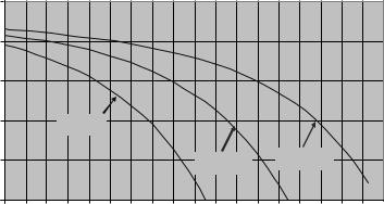
A general drawback of higher-order modulation schemes such as 16QAM and 64QAM, where information is encoded also in the instantaneous amplitude of the modulated signal, is that the modulated signal will have larger variations, and thus also larger peaks, in its instantaneous power. This can be seen from Figure 3.3 which illustrates the distribution of the instantaneous power, more specifically the probability that the instantaneous power is above a certain value, for QPSK, 16QAM, and 64QAM, respectively. Clearly, the probability for large peaks in the instantaneous power is higher in case of higher-order modulation.
Larger peaks in the instantaneous signal power imply that the transmitter power amplifier must be over-dimensioned to avoid that power-amplifier non-linearities, occurring at high instantaneous power levels, cause corruption to the signal to be transmitted. As a consequence, the power-amplifier efficiency will be reduced, leading to increased power consumption. In addition, there will be a negative impact on the power-amplifier cost. Alternatively, the average transmit power must be reduced, implying a reduced range for a given data rate. High poweramplifier efficiency is especially important for the mobile terminal, i.e. in the uplink direction, due to the importance of low mobile-terminal power consumption and cost. For the base station, high power-amplifier efficiency, although far from irrelevant, is still somewhat less important. Thus, large peaks in the instantaneous signal power is less of an issue for the downlink compared to the uplink and, consequently, higher-order modulation is more suitable for the downlink compared to the uplink.
High data rates in mobile communication |
39 |
|
1.0E 00 |
|
|
|
|
|
|
|
|
|
|
|
|
|
|
|
|
|
|
|
1.0E 01 |
|
|
|
|
|
|
|
|
|
|
|
|
|
|
|
|
|
|
probability |
1.0E 02 |
|
|
|
|
|
|
|
|
|
|
|
|
|
|
|
|
|
|
|
|
|
|
|
|
|
|
|
|
|
|
|
|
|
|
|
|
|
|
Bit-error |
1.0E 03 |
|
|
QPSK |
|
|
|
|
|
|
|
|
|
|
|
|
|
|
|
|
|
|
|
|
|
|
|
|
|
|
|
|
|
|
|
|
|||
|
|
|
|
|
|
|
|
|
|
|
|
|
|
|
|
|
|
|
|
|
1.0E 04 |
|
|
|
|
|
|
|
|
|
16QAM |
|
64QAM |
|
|
|
|||
|
1.0E 05 |
|
|
|
|
|
|
|
|
|
|
|
|
|
|
|
|
|
|
|
0 |
1 |
2 |
3 |
4 |
5 |
6 |
7 |
8 |
9 |
10 |
11 |
12 |
13 |
14 |
15 |
16 |
17 |
18 |
|
|
|
|
|
|
|
|
|
Eb/N0 [dB] |
|
|
|
|
|
|
|
|
||
Figure 3.3 Distribution of instantaneous power for different modulation schemes. Same average power in all cases.
3.3 Wider bandwidth including multi-carrier transmission
As was shown in Section 3.1, transmission with a high-bandwidth utilization is fundamentally power in-efficient in the sense that it will require un-proportionally high signal-to-noise and signal-to-interference ratios for a given data rate. Providing very high data rates within a limited bandwidth, for example by means of higher-order modulation, is thus only possible in situations where relatively high signal-to-noise and signal-to-interference ratios can be made available, for example in small-cell environments with low traffic load or for mobile terminals close to the cell site.
Instead, to provide high data rates as efficiently as possible in terms of required signal-to-noise and signal-to-interference ratios, implying as good coverage as possible for high data rates, the transmission bandwidth should be at least of the same order as the data rates to be provided.
Having in mind that the provisioning of higher data rates with good coverage is one of the main targets for the evolution of 3G mobile communication, it can thus be concluded that support for even wider transmission bandwidth is an important part of this evolution.
However, there are several critical issues related to the use of wider transmission bandwidths in a mobile-communication system:
•Spectrum is, as already mentioned, often a scarce and expensive resource, and it may be difficult to find spectrum allocations of sufficient size to allow for
very wideband transmission, especially at lower-frequency bands.
40 |
3G Evolution: HSPA and LTE for Mobile Broadband |
•The use of wider transmission and reception bandwidths has an impact on the complexity of the radio equipment, both at the base station and at the mobile terminal. As an example, a wider transmission bandwidth has a direct impact on the transmitter and the receiver sampling rates, and thus on the complexity and power consumption of digital-to-analog and analog-to-digital converters as well as front-end digital signal processing. RF components are also, in general, more complicated to design and more expensive to produce, the wider the bandwidth they are to handle.
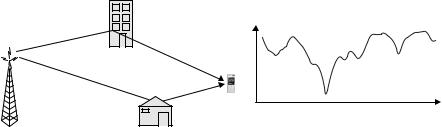
The two issues above are mainly outside the scope of this book. However, a more specific technical issue related to wider-band transmission is the increased corruption of the transmitted signal due to time dispersion on the radio channel. Time dispersion occurs when the transmitted signal propagates to the receiver via multiple paths with different delays (see Figure 3.4a). In the frequency domain, a time-dispersive channel corresponds to a non-constant channel frequency response as illustrated in Figure 3.4b. This radio-channel frequency selectivity will corrupt the frequency-domain structure of the transmitted signal and lead to higher error rates for given signal-to-noise/interference ratios. Every radio channel is subject to frequency selectivity, at least to some extent. However, the extent to which the frequency selectivity impacts the radio communication depends on the bandwidth of the transmitted signal with, in general, larger impact for wider-band transmission. The amount of radio-channel frequency selectivity also depends on the environment with typically less frequency selectivity (less time dispersion) in case of small cells and in environments with few obstructions and potential reflectors, such as rural environments.
It should be noted that Figure 3.4b illustrates a ‘snapshot’ of the channel frequency response. As a mobile terminal is moving through the environment, the detailed structure of the multi-path propagation, and thus also the detailed structure of the channel frequency response, may vary rapidly in time. The rate of the variations in the channel frequency response is related to the channel Doppler spread, fD,
Frequency
(a) |
(b) |
Figure 3.4 Multi-path propagation causing time dispersion and radio-channel frequency
selectivity.
High data rates in mobile communication |
41 |
defined as fD = v/c · fc, where v is the speed of the mobile terminal, fc is the carrier frequency (e.g. 2 GHz), and c is the speed of light.
Receiver-side equalization [50] has for many years been used to counteract signal corruption due to radio-channel frequency selectivity. Equalization has been shown to provide satisfactory performance with reasonable complexity at least up to bandwidths corresponding to the WCDMA bandwidth of 5 MHz (see, e.g. [29]). However, if the transmission bandwidth is further increased up to, for example 20 MHz, which is the target for the 3GPP Long-Term Evolution, the complexity of straightforward high-performance equalization starts to become a serious issue. One option is then to apply less optimal equalization, with a corresponding negative impact on the equalizer capability to counteract the signal corruption due to radio-channel frequency selectivity and thus a corresponding negative impact on the radio-link performance.
An alternative approach is to consider specific transmission schemes and signal designs that allow for good radio-link performance also in case of substantial radiochannel frequency selectivity without a prohibitively large receiver complexity. In the following, two such approaches to wider-band transmission will be discussed:
1.The use of different types of multi-carrier transmission, that is transmitting an overall wider-band signal as several more narrowband frequency-multiplexed signals, see below. One special case of multi-carrier transmission is OFDM transmission to be discussed in more detail in Chapter 4.
2.The use of specific single-carrier transmission schemes, especially designed to allow for efficient but still reasonably low-complexity equalization. This is further discussed in Chapter 5.
3.3.1Multi-carrier transmission
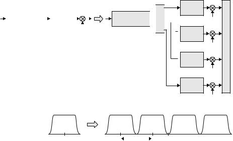
One way to increase the overall transmission bandwidth, without suffering from increased signal corruption due to radio-channel frequency selectivity, is the use of so-called multi-carrier transmission. As illustrated in Figure 3.5, multi-carrier transmission implies that, instead of transmitting a single more wideband signal, multiple more narrowband signals, often referred to as subcarriers, are frequency multiplexed and jointly transmitted over the same radio link to the same receiver. By transmitting M signals in parallel over the same radio link, the overall data rate can be increased up to M times. At the same time, the impact in terms of signal corruption due to radio-channel frequency selectivity depends on the bandwidth of each subcarrier. Thus, the impact from a frequency-selective channel is essentially the same as for a more narrowband transmission scheme with a bandwidth that corresponds to the bandwidth of each subcarrier.
42 |
3G Evolution: HSPA and LTE for Mobile Broadband |
Narrowband transmission
|
|
|
RF modulation |
|||||
|
|
|
|
|
|
|
|
|
Channel coding, |
|
|
Spectrum |
|
|
|
|
|
mo |
|
|
shaping |
|
|
|
|
|
|
|
|
|
|
|
|
||
modulation, etc. |
|
|
|
|
|
|
|
|
|
|
|
|
|
|
|
|
|
|
|
|
|
|
|
|
|
|
fc
Wideband multi-carrier transmission
RF modulation
Channel coding, modulation, etc.

 Demux
Demux
Spectrum
shaping
fc 3/2 f
 Spectrum
shaping
fc 1/2 f 
 Spectrum
shaping
fc 1/2 f
Spectrum
shaping
fc 3/2 f
fc |
|
fc |
f |
Figure 3.5 Extension to wider transmission bandwidth by means of multi-carrier transmission.
A drawback of the kind of multi-carrier evolution outlined in Figure 3.5, where an existing more narrowband radio-access technology is extended to a wider overall transmission bandwidth by the parallel transmission of M more narrowband carriers, is that the spectrum of each subcarrier does typically not allow for very tight subcarrier ‘packing.’ This is illustrated by the ‘valleys’ in the overall multicarrier spectrum outlined in the lower part of Figure 3.5. This has a somewhat negative impact on the overall bandwidth efficiency of this kind of multi-carrier transmission.
As an example, consider a WCDMA multi-carrier evolution towards wider bandwidth. WCDMA has a modulation rate, also referred to as the WCDMA chip rate, of fcr = 3.84 Mchips/s. However, due to spectrum shaping, even the theoretical WCDMA spectrum, not including spectrum widening due to transmitter imperfections, has a bandwidth that significantly exceeds 3.84 MHz. More specifically, as can be seen in Figure 3.6, the theoretical WCDMA spectrum has a raised-cosine shape with roll-off α = 0.22. As a consequence, the bandwidth outside of which the WCDMA theoretical spectrum equals zero is approximately 4.7 MHz (see right part of Figure 3.6).
For a straightforward multi-carrier extension of WCDMA, the subcarriers must thus be spaced approximately 4.7 MHz from each other to completely avoid