

3G Evolution. HSPA and LTE for Mobile Broadband
.pdfScheduling, link adaptation and hybrid ARQ |
125 |
retransmissions and can thus be seen as implicit link adaptation. However, in contrast to link adaptation based on explicit estimates of the instantaneous channel conditions, hybrid ARQ with soft combining implicitly adjusts the coding rate based on the result of the decoding. In terms of overall throughput this kind of implicit link adaptation can be superior to explicit link adaptation as additional redundancy is only added when needed, that is when previous higher-rate transmissions were not possible to decode correctly. Furthermore, as it does not try to predict any channel variations, it works equally well, regardless of the speed of which the terminal is moving. Since implicit link adaptation can provide a gain in system throughput, a valid question is why explicit link adaptation at all is necessary. One major reason for having explicit link adaptation is the reduced delay. Although relying on implicit link adaptation alone is sufficient from a system throughput perspective, the end-user service quality may not be acceptable from a delay perspective.
8
WCDMA evolution: HSPA and MBMS
The first step in the evolution of WCDMA radio access is the introduction of HighSpeed Downlink Packet Access (HSDPA) in Release 5 of the 3GPP/WCDMA specifications. Although packet-data communication is supported already in the first release of the WCDMA standard, HSDPA brings further enhancements to the provisioning of packet-data services in WCDMA, both in terms of system and end-user performance. The downlink packet-data enhancements of HSDPA are complemented by Enhanced Uplink, introduced in Release 6 of the 3GPP/ WCDMA specifications. HSDPA and Enhanced Uplink are often jointly referred to as High-Speed Packet Access (HSPA).
As discussed in Chapter 2, important requirements for cellular systems providing packet-data services are high data rates and low delays while, as at the same time, maintaining good coverage and providing high capacity. To achieve this, HSPA introduces several of the basic techniques described in Part II into WCDMA, such as higher order modulation, fast (channel-dependent) scheduling and rate control, and fast hybrid ARQ with soft combining. Altogether, HSPA provides downlink and uplink data rates up to approximately 14 and 5.7 Mbit/s, respectively, and significantly reduced round trip times and improved capacity, compared to Release 99.
3GPP Release 6 also brings efficient support for broadcast services into WCDMA through the introduction of Multimedia Broadcast Multicast Services (MBMS), suitable for applications like mobile TV. With MBMS, multiple terminals may receive the same broadcast transmission instead of the network transmitting the same information individually to each of the users. Naturally, this will lead to an improvement in the resource utilization when several users in a cell receive the same content. As a consequence of the broadcast transmission, user-specific adaptation of the transmission parameters cannot be used and diversity as a mean
129
130 |
3G Evolution: HSPA and LTE for Mobile Broadband |
to maintain good coverage is important. For MBMS, macro-diversity through multi-cell reception is employed for this purpose.
The evolution of the WCDMA radio access continues and will continue also in the future. For example, 3GPP Release 7 introduces several new features. MIMO is a tool to further improve capacity and especially the HSPA peak data rates. Continuous Packet Connectivity aims at providing an ‘always-on’ service perception terminals.
In parallel to enhancements of the radio-access specifications, there is an ongoing effort in advanced receiver structures. These improvements, which can provide a significant gain in both system and end-user performance, are to a large extent implementation specific, although the receiver-performance requirements as such are subject to standardization.
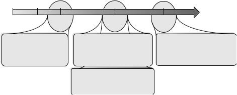
As a summary, the evolution of WCDMA is illustrated in Figure 8.1.
In the following chapters, the evolution of WCDMA is discussed. Chapter 9 provides a description of HSDPA, including how several of the basic technologies from Part II have been incorporated in the WCDMA radio access. A similar description for Enhanced Uplink is provided in Chapter 10. MBMS is described in Chapter 11. Finally, Chapter 12 describes Release 7 features such as MIMO, Continuous Packet Connectivity, and advanced receivers, representing the evolution of HSPA. The chapters have a similar structure. The first part of each chapter provides a high-level overview of the respective feature. This can be used to get a quick understanding of how HSPA and MBMS work and can to a large extent be read on its own. The overview is followed by a description on how the key technologies have been integrated into WCDMA and why certain solutions were chosen. Finally, at the end of the chapter, additional details are provided.
R99 |
Rel 4 |
Rel 5 |
Rel 6 |
Rel 7 |
|
WCDMA |
|
HSPA |
HSPA evolution |
|
|
HSDPA |
Enhanced |
MIMO |
|
|
|
Uplink |
CPC |
|
|
|
MBMS |
|
• HSDPA – improved downlink |
• Enhanced Uplink – improved |
packet-data support |
uplink packet-data support |
– Reduced delays |
– Reduced delays |
– 14 Mbit/s peak data rate |
– 5.74 Mbit/s peak data rate |
– ~3 R99 capacity |
– ~2 R99 capacity |
|
• MBMS – Multimedia Broadcast |
|
Multicast Services |
|
– Introduction of (improved) |
|
broadcast services (‘Mobile TV’) |
•MIMO and higher-order modulation
–28 Mbit/s DL peak data rate
–11 Mbit/s UL peak data rate
•Continuous Packet Connectivity
–‘Always on’ user experience
Figure 8.1 WCDMA evolution.
WCDMA evolution: HSPA and MBMS |
131 |
The remainder of this chapter contains an overview of the first release of WCDMA. The intention is to provide the reader with an understanding of the foundation upon which HSPA and MBMS are built. The reader already familiar with WCDMA may want to skip the remainder of this chapter.
8.1 WCDMA: brief overview
This section provides a brief overview of WCDMA Release 99 to serve as a background to the subsequent sections. As a thorough walk through of WCDMA is a topic of its own and beyond the scope of this book, the reader is referred to other books and articles [4, 14, 121] for a detailed description. WCDMA is a versatile and highly flexible radio interface that can be configured to meet the requirements from a large number of services, but the focus for the description below is the functionality commonly used to support packet-data transmissions. The main purpose is to provide a brief background to WCDMA to put the enhancements described later on into a perspective.
8.1.1 Overall architecture
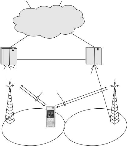
WCDMA is based on a hierarchical architecture [103] with the different nodes and interfaces as illustrated in Figure 8.2. A terminal, also referred to as User Equipment (UE) in 3GPP terminology, communicates with one (or several) NodeBs. In the WCDMA architecture, the term NodeB refers to a logical node, responsible for physical-layer processing such as error-correcting coding, modulation and spreading, as well as conversion from baseband to the radio-frequency signal transmitted from the antenna. A NodeB is handling transmission and reception in one or several cells. Three-sector sites are common, where each NodeB is handling transmissions in three cells, although other arrangements of the cells belonging to one NodeB can be thought of, for example, a large number of indoor cell or several cells along a highway belonging to the same NodeB. Thus, a base station is a possible implementation of a NodeB.
The Radio Network Controller (RNC) controls multiple NodeBs. The number of NodeBs connected to one RNC varies depending on the implementation and deployment, but up to a few hundred NodeBs per RNC is not uncommon. The RNC is, among other things, in charge of call setup, quality-of-service handling, and management of the radio resources in the cells for which it is responsible. The ARQ protocol, handling retransmissions of erroneous data, is also located in the RNC. Thus, in Release 99, most of the ‘intelligence’ in the radio-access network resides in the RNC, while the NodeBs mainly acts as modems.
Finally, the RNCs are connected to the Internet and the traditional wired telephony network through the core network.
132 |
3G Evolution: HSPA and LTE for Mobile Broadband |
PSTN |
Internet |
|
Core network |
RNC |
RNC |
To other NodeBs |
To other NodeBs |
|
Dedicated channels |
NodeB
Figure 8.2 WCDMA radio-access network architecture.
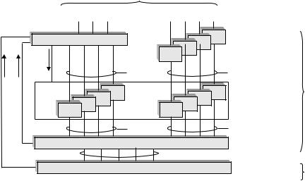
Most modern communication systems structure the processing into different layers and WCDMA is no exception. The layered approach is beneficial as it provides a certain structure to the overall processing where each layer is responsible for a specific part of the radio-access functionality. The different protocol layers used in WCDMA are illustrated in Figure 8.3 and briefly described [98].
User data from the core network, for example in the form of IP packets, are first processed by the Packet Data Convergence Protocol (PDCP) which performs (optional) header compression. IP packets have a relatively large header, 40 bytes for IPv4 and 60 bytes for IPv6, and to save radio-interface resources, header compression is beneficial.
WCDMA evolution: HSPA and MBMS |
|
|
133 |
|
|
To core network |
|
||
|
Control plane |
|
User plane |
|
|
RRC |
Layer 3 |
PDCP |
|
Measurements |
PDCP |
|
||
Control |
|
PDCP |
|
|
|
|
PDCP |
|
|
|
|
Signaling |
|
Radio |
|
|
channels |
|
access bearers |
|
RLC |
|
RLC |
RNC |
|
RLC |
|
RLC |
Layer 2 RLC |
|
RLC |
|
RLC |
|
|
RLC |
|
RLC |
|
 Control
|
Logical channels |
|
MAC |
Layer 2 MAC |
|
|
Transport channels |
|
Physical Layer |
Layer 1 |
NodeB |
|
Figure 8.3 WCDMA protocol architecture.
The Radio Link Protocol (RLC) is, among other things, responsible for segmentation of the IP packets into smaller units known as RLC Protocol Data Units (RLC PDUs). At the receiving end, the RLC performs the corresponding reassembly of the received segments. The RLC also handles the ARQ protocol. For packet-data services, error-free delivery of data is often essential and the RLC can therefore be configured to request retransmissions of erroneous RLC PDUs in this case. For each incorrectly received PDU, the RLC requests a retransmission. The need for a retransmission is indicated by the RLC entity at the receiving end to its peer RLC entity at the transmitting end by means of status reports.
The Medium Access Control (MAC) layer offers services to the RLC in the form of so-called Logical Channels. The MAC layer can multiplex data from multiple logical channels. It is also responsible for determining the Transport Format of the data sent to the next layer, the physical layer. In essence, the transport format is the instantaneous data rate used over the radio link and is better understood once the interface between the MAC and physical layer has been described. This interface is specified through so-called Transport Channels over which data in the form of transport blocks are transferred. There are several transport channels defined in WCDMA; for an overview of those and the allowed mappings of logical channels to transport channels, the reader is referred to [98].
In each Transmission Time Interval (TTI) one or several transport blocks are fed from the MAC layer to the physical layer, which performs coding, interleaving,
134 |
3G Evolution: HSPA and LTE for Mobile Broadband |
multiplexing, spreading, etc., prior to data transmission. Thus, for WCDMA, the TTI is the time which the interleaver spans and the time it takes to transmit the transport block over the radio interface. A larger TTI implies better time diversity, but also a longer delay. In the first release, WCDMA relies on TTI lengths of 10, 20, 40, and 80 ms. As will be seen later, HSPA introduces additional 2 ms TTI to reduce the latency.
To support different data rates, the MAC can vary the transport format between consecutive TTIs. The transport format consists of several parameters describing how the data shall be transmitted in a TTI. By varying the transport-block size and/or the number of transport blocks, different data rates can be realized.
At the bottom of the protocol stack is the physical layer. The physical layer is responsible for operations such as coding, spreading and data modulation, as well as modulation of the radio-frequency carrier.
PDCP, RLC, MAC, and physical layer, are configured by the Radio Resource Control (RRC) protocol. RRC performs admission control, handover decisions, and active set management for soft handover. By setting the parameters of the RLC, MAC, and physical layers properly, the RRC can provide the necessary quality-of-service requested by the core network for a certain service.
On the network side, the MAC, RLC and RRC entities in Release 99 are all located in the RNC while the physical layer is mainly located in the NodeB. The same entities also exist in the UE. For example, the MAC in the UE is responsible for selecting the transport format for uplink transmissions from a set of formats configured by the network. However, the handling of the radio resources in the cell is controlled by the RRC entity in the network and the UE obeys the RRC decisions taken in the network.
8.1.2Physical layer
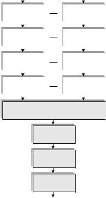
The basis for the physical layer of WCDMA is spreading of the data to be transmitted to the chip rate, which equals 3.84 Mchip/s. It is also responsible for coding, transport-channel multiplexing, and modulation of the radio-frequency carrier. A simplified illustration of the physical layer processing is provided in Figure 8.4.
To each transport block to be transmitted, the transmitter physical layer adds a Cyclic Redundancy Check (CRC) for the purpose of error detection. If the receiver detects an error, the RLC protocol in the receiver is informed and requests
WCDMA evolution: HSPA and MBMS |
135 |
|||||
Transport channel |
Transport channel |
|||||
|
|
|
|
|
|
|
|
|
|
|
|
|
|
|
|
|
|
|
|
|
|
CRC |
|
CRC |
|
||
|
attachment |
|
attachment |
|
||
|
|
|
|
|
|
|
|
|
|
|
|
|
|
|
|
|
|
|
|
|
|
Turbo coding |
|
Turbo coding |
|
||
|
|
|
|
|
|
|
|
|
|
|
|
|
|
|
|
|
|
|
|
|
|
Rate matching |
|
Rate matching |
|
||
|
|
|
|
|
|
|
|
|
|
|
|
|
|
|
|
|
|
|
|
|
|
Interleaving |
|
Interleaving |
|
||
|
|
|
|
|
|
|
|
|
|
|
|
|
|
Multiplexing
Interleaving
Modulation
Spreading
Physical channel
Figure 8.4 Simplified view of physical layer processing in WCDMA.
a retransmission. After CRC attachment, the data is encoded using a rate-1/3 Turbo coder (convolutional coding is also supported by WCDMA, but typically not used for packet-data services). Rate matching by means of puncturing or repetition of the coded bits is used to fine-tune the code rate and multiple coded and interleaved transport channels can be multiplexed together, forming a single stream of bits to be spread to the chip rate and subsequently modulated. For the downlink, QPSK modulation is used, while the uplink uses BPSK. The resulting stream of modulation symbols is mapped to a physical channel and subsequently digital- to-analog converted and modulated onto a radio-frequency carrier. In principle, each physical channel corresponds to a unique spreading code, used to separate transmissions to/from different users.
The spreading operation actually consists of two steps: spreading to the chip rate by using orthogonal channelization codes with a length equal to the symbol time
136 |
3G Evolution: HSPA and LTE for Mobile Broadband |
SF 1 |
1 |
|
|
|
|
||
SF 2 |
1 1 |
1 1 |
|
1 1 1 1 |
1 1 1 1 |
||
|
|||
SF 4 |
1 1 1 1 |
1 1 1 1 |
|
|
|
SF 8
SF 16
SF 32
SF 64
SF 128
SF 256
Figure 8.5 Channelization codes.
followed by scrambling using non-orthogonal scrambling sequences with a length equal to the 10 ms radio frame.
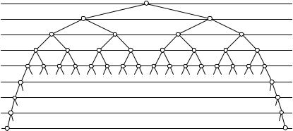
The channelization codes are so-called Orthogonal Variable Spreading Factor (OVSF) codes, defined by the tree structure in Figure 8.5. A key property of the OVSF codes is the mutual orthogonality between data streams spread with different OVSF codes, even if the data rate, and therefore the spreading factors, are different. This holds as long as the different OVSF codes are selected from different branches of the channelization code tree and transmitted with the same timing. By selecting different spreading factors, physical channels with different data rates can be provided.
In the downlink, data to a certain user, including the necessary control information, is carried on one QPSK-modulated Dedicated Physical Channel (DPCH) corresponding to one OVSF code. By varying the spreading factor, different DPCH symbol rates can be provided. The spreading factor is determined by the transport format selected by the MAC layer. There is also a possibility to use multiple physical channels to a single user for the highest data rates.
Some downlink channelization codes are pre-allocated for specific purposes. One of the most important is the code used for reference signal transmission, in WCDMA known as the Common Pilot Channel (CPICH). The CPICH contains known data and is used as a reference for downlink channel estimation by all UEs in the cell. There is also a pre-allocated control channel carrying cell-specific control information.
Since physical channels are separated by OVSF codes, transmissions on different physical channels are orthogonal and will not interfere with each other. The
WCDMA evolution: HSPA and MBMS |
137 |
WCDMA downlink is therefore often said to be orthogonal. However, at the receiver side, orthogonality will partly be lost in case of a frequency-selective channel. As discussed in Chapter 5, this will cause signal corruption to the received signal and result in interference between different codes used for downlink transmission. Such signal corruption can be counteracted by an equalizer.
WCDMA supports asynchronous operation, where transmissions from different cells are not time synchronized. To separate different cells, the scrambling is cell specific in the downlink. A terminal receiving transmissions from one cell will therefore be interfered by transmissions in neighboring cells as the scrambling sequences are non-orthogonal. This interference will be suppressed by the terminal receiver with a factor proportional to the processing gain (the processing gain is given by the spreading factor divided by the code rate after rate matching).
In the uplink, data is carried on a BPSK-modulated Dedicated Physical Data Channel (DPDCH). Similar to the downlink, different data rates are realized by using different spreading factors for the DPDCH. Coherent demodulation is used also in the uplink, which requires a channel estimate. Unlike the downlink, where a common pilot signal is used, uplink transmissions originate from different locations. Therefore, a common pilot cannot be used and each user must have a separate pilot signal. This is carried on the Dedicated Physical Control Channel, DPCCH. The DPCCH also carries information about the transport format of the data transmitted on the DPDCH. This information is required by the physical layer in the NodeB for proper demodulation.
User-specific scrambling is used in the WCDMA uplink and the channelization codes are only used to separate different physical channels from the same terminal. The same set of channelization codes can therefore be used by multiple UEs. As the transmissions from different terminals are not time synchronized, separation of different terminals by the use of OVSF codes is not possible. Hence, the uplink is said to be non-orthogonal and different users’ transmissions will interfere with each other.
The fact that the uplink is non-orthogonal implies that fast closed-loop power control is an essential feature of WCDMA. With fast closed-loop power control, the NodeB measures the received signal-to-interference ratio (SIR) on the DPCCH received from each terminal and 1500 times per second commands the terminals to adjust its transmission power accordingly. The target of the power control is to ensure that the received SIR of the DPCCH is at an appropriate level for each user. Note that the required SIR depends on the data rate. This SIR target may very well be different for different users. If the SIR is below the target, that is