

3G Evolution. HSPA and LTE for Mobile Broadband
.pdf158 |
3G Evolution: HSPA and LTE for Mobile Broadband |
be set up for a user, although a typical number of processes is six. This provides approximately 2.8 ms of processing time in the NodeB from the reception of the ACK/NAK until the NodeB can schedule a (re)transmission to the UE in the same hybrid-ARQ process.
Downlink control signaling is used to inform the UE which of the hybrid-ARQ processes that is used for the current TTI. This is important information to the UE as it is needed to do soft combining with the correct soft buffer; each hybrid-ARQ process has its own soft buffer.
One result of having multiple independent hybrid-ARQ processes operated in parallel is that decoded transport blocks may appear out-of-sequence. For example, a retransmission may be needed in hybrid-ARQ process number one, while process number two did successfully receive the data after the first transmission attempts. Therefore, the transport block transmitted in process number two will be available for forwarding to higher layers at the receiver side before the transport block transmitted in process number one, although the transport blocks were originally transmitted in a different order. This is illustrated in Figure 9.10. As the RLC protocol assumes data to appear in the correct order, a reordering mechanism is used between the outputs from the multiple hybrid-ARQ processes and the RLC protocol. The reordering mechanism is described in more detail in Section 9.3.4.
9.2.6Data flow
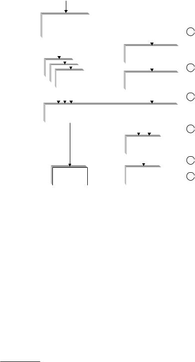
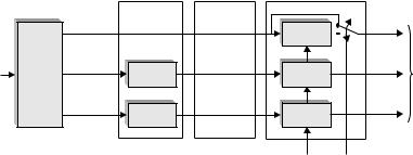
To illustrate the flow of user data through the different layers, an example radiointerface protocol configuration is shown in Figure 9.11. For the UE in this example, an IP-based service is assumed, where the user data is mapped to the HS-DSCH.
For signaling purposes in the radio network, several signaling radio bearers are configured in the control plane. In Release 5, signaling radio bearers cannot be mapped to the HS-DSCH, and consequently dedicated transport channels must be used, while this restriction is removed in Release 6 to allow for operation completely without dedicated transport channels in the downlink.
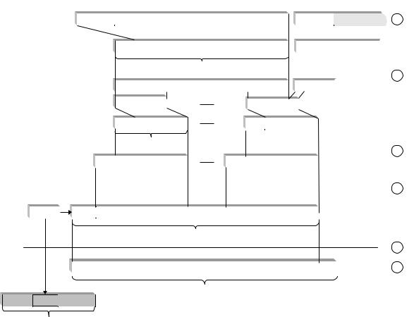
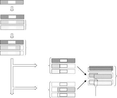
Figure 9.12 illustrates the data flow at the reference points shown in Figure 9.11. In this example an IP-based service is assumed. The PDCP performs (optional) IP header compression. The output from the PDCP is fed to the RLC protocol entity. After possible concatenation, the RLC SDUs are segmented into smaller blocks of typically 40 bytes. An RLC PDU is comprised of a data segment and the RLC header. If logical-channel multiplexing is performed in MAC-d, a 4-bit header is added to form a MAC-d PDU. In MAC-hs, a number of MAC-d PDUs,
High-Speed Downlink Packet Access |
159 |
|
|
|
|
|
|
|
|
|
|
|
|
|
|
|
|
|
|
|
|
|
|
|
RRC |
|
|
|
|
|
|
RBs |
1 |
||||||||
|
|
|
|
|
|
|
|
|
|
|
|
|
|
|
|
||||
|
|
|
|
|
|
|
|
|
|
|
|
|
|
|
|
|
|
||
|
|
|
|
|
|
SRBs |
|
|
|
|
|
|
|
|
|
||||
|
|
|
|
|
|
|
|
|
|
|
|
|
|
|
|||||
|
|
|
|
|
|
|
|
|
PDCP |
|
|
||||||||
|
|
|
|
|
|
|
|
|
|
|
|
|
|
|
|
||||
|
|
|
|
|
|
|
|
|
|
|
|
|
|
|
|
|
|
|
2 |
|
|
|
|
|
|
|
|
|
|
|
|
|
|
|
|
|
|
|
|
|
|
|
|
|
|
|
|
|
|
|
|
|
|
|
|
|
|
|
|
|
|
|
|
RLC |
|
|
|
|
|
|
|
|
|
|
|
|
|
|
|
|
|
|
|
|
|
|
|
|
|
|
|
RLC |
|
|
|||||
|
|
|
|
|
|
|
|
|
|
|
|
|
|
||||||
|
|
|
|
|
|
|
|
|
|
|
|
|
|
|
|
||||
|
|
|
|
|
|
|
|
|
|
|
|
|
|
|
|
|
|
|
|
|
|
|
|
|
|
DCCHs |
|
|
|
|
|
DTCHs |
|
3 |
|||||
|
|
|
|
|
|
|
|
|
|
|
|
|
|
|
|
|
|
|
|
|
|
|
|
|
|
|
|
|
|
|
MAC-d |
|
|
||||||
|
|
|
|
|
|
|
|
|
|
|
|
|
|
|
|
|
|
|
4 |
|
|
|
|
|
|
|
|
|
|
|
|
|
|
|
|
MAC-d flows |
|||
|
|
|
|
|
|
DCH(s) |
|
|
|
|
|
|
|
|
|
||||
|
|
|
|
|
|
|
MAC-hs |
|
|
|
|||||||||
|
|
|
|
|
|
|
|
|
|
|
|
|
|
|
|
|
|
5 |
|
|
|
|
|
|
|
|
|
|
|
|
|
|
|
HS-DSCH |
|||||
|
|
|
|
|
|
|
|
|
|
|
|
|
|
|
|
|
|
|
|
|
|
|
|
L1 |
|
|
|
L1 |
|
|
6 |
||||||||
|
|
|
(DPCH) |
|
|
|
(HS-PDSCH) |
|
|
||||||||||
|
|
|
|
|
|
|
|||||||||||||
|
|
|
|
|
|
|
|
|
|
|
|
|
|
|
|
|
|
|
|
Figure 9.11 Protocol configuration when HS-DSCH is assigned. The numbers in the rightmost part of the figure corresponds to the numbers to the right in Figure 9.12.
possibly of variable size, are assembled and a MAC-hs header is attached to form one transport block, subsequently coded and transmitted by the physical layer.
9.2.7 Resource control for HS-DSCH
With the introduction of HSDPA, parts of the radio resource management are handled by the NodeB instead of the RNC. This is a result of introducing channeldependent scheduling and rate control in the NodeB in order to exploit rapid channel variations. However, the RNC still has the overall responsibility for radio-resource management, including admission control and handling of intercell interference. Therefore, new measurement reports from the NodeB to the RNC have been introduced, as well as mechanisms for the RNC to set the limits within which the NodeB are allowed to handle the HSDPA resources2 in the cell.
2 Note that many of these measurements were extended in Rel6 to include Enhanced Uplink Downlink control channels in addition to the HSDPA-related channels.
|
|
|
|
|
|
40 bytes (IPv4) |
Typically up to 1460 bytes |
|
|
|
|
|
|
|
|
|
||||||||
IP |
|
|
|
|
|
|
|
|
|
|
|
|
|
|
|
|
|
|
|
|
||||
|
|
|
|
IP header |
|
|
Payload (application data) |
|
|
IP header |
|
|
1 |
|||||||||||
|
|
|
|
|
|
|
|
|
|
|
|
|
|
|
|
|
|
|
|
|
|
|
|
|
|
|
|
|
|
|
|
|
|
|
|
|
|
|
|
|
|
|
|
|
|
|
|
|
|
L2 PDCP |
|
|
2 or 3 bytes |
PDCP |
|
|
|
PDCP SDU |
|
|
PDCP |
|
|
|
|
|
|
|||||||
|
|
header |
|
|
|
|
|
header |
|
|
|
|
|
|
||||||||||
|
|
|
|
|
|
|
|
|
|
|
|
PDCP PDU |
|
|
|
|
|
|
|
2 |
||||
|
|
|
|
|
|
|
|
|
|
|
|
|
|
|
|
|
|
|
|
|
|
|||
|
|
|
|
|
|
|
|
|
|
|
|
|
|
|
|
|
|
|
|
|
|
|||
|
|
|
|
|
|
|
|
|
|
|
|
RLC SDU |
|
|
RLC SDU |
|
|
|
|
|||||
L2 RLC |
|
Typically 40 bytes |
|
|
|
|
|
|
|
|
|
|
|
|
|
|
|
|
|
|||||
|
|
|
|
|
|
|
|
|
|
|
|
|
|
|
|
|
|
|||||||
|
|
|
|
|
|
|
|
|
|
|
|
|
|
|
|
|
|
|
|
|
|
|
|
|
|
|
|
|
|
|
2–4 bytes |
RLC |
|
|
|
|
|
RLC |
|
|
|
|
|
|
|
|
|
||
|
|
|
|
|
|
header |
|
|
|
|
|
header |
|
|
|
|
|
|
|
|
|
|||
|
|
|
|
|
|
|
|
|
|
RLC PDU |
|
|
|
|
|
|
|
|
|
|
|
3 |
||
|
|
|
|
|
|
|
|
|
|
|
|
|
|
|
|
|
|
|
|
|
|
|||
|
|
|
|
|
|
|
|
|
|
|
|
|
|
|
|
|
|
|
|
|
|
|||
L2 MAC-d |
|
|
0 or 4 bits |
MAC-d |
|
MAC-d SDU |
|
|
MAC-d |
|
MAC-d SDU |
|
|
|
|
|
|
|||||||
|
|
|
|
|
|
|
header |
|
|
|
|
|
header |
|
|
|
|
|
|
|
|
|
|
|
|
|
|
|
|
|
|
|
|
|
|
|
|
|
|
|
|
|
|
|
|
|
4 |
||
|
|
Typically 21 bit |
|
|
|
|
|
|
|
|
|
|
|
|
|
|||||||||
|
|
|
|
|
|
|
|
|
|
|
|
|
|
|
|
|
|
|||||||
|
|
|
|
|
|
|
|
|
|
|
|
|
|
|
|
|
|
|
|
|
|
|||
L2 MAC-hs |
HARQ |
|
MAC-hs |
|
|
|
|
|
|
|
|
|
|
|
|
|
|
|
|
|
|
|||
info |
|
|
|
header |
|
|
|
|
|
|
|
|
|
|
|
|
|
|
|
|
|
|
||
|
|
|
|
|
|
|
|
|
|
|
|
Transport block |
|
|
|
|
|
|
|
|
|
|||
|
|
|
|
|
|
|
|
|
|
|
|
|
|
|
|
|
|
|
|
|
5 |
|||
L1 |
|
|
|
|
|
|
|
|
|
|
|
|
|
|
|
|
|
|
|
6 |
||||
|
|
|
|
|
|
|
|
|
|
|
|
|
|
|
|
|
CRC |
|
||||||
Mapped onto HS-PDSCH
TFRI HARQ CRC
Mapped onto HS-SCCH
Figure 9.12 Data flow at UTRAN side.
160
Broadband Mobile for LTE and HSPA Evolution: 3G
High-Speed Downlink Packet Access |
161 |
NodeB
Scheduler
Transmitted carrier power of all codes not used for HS-PDSCH or HS-SCCH
HSDPA total power limitation
HS-DSCH provided bit rate measurement
HS-DSCH required power measurement
Guaranteed bit rate
RNC
Admission control
Congestion control
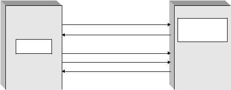
Figure 9.13 Measurements and resource limitations for HSDPA.
To limit the transmission power used for HSDPA, the RNC can set the maximum amount of power the NodeB is allowed to use for HSDPA-related downlink transmissions. This ensures that the RNC has control of the maximum amount of interference a cell may generate to neighboring cells. Within the limitation set by the RNC, the NodeB is free to manage the power spent on the HSDPA downlink channels. If the quantity is absent (or larger than the total NodeB power), the NodeB may use all available power for downlink transmissions on the HS-DSCH and HS-SCCH.
Admission control in the RNC needs to take into account the amount of power available in the NodeB. Only if there is a sufficient amount of transmission power available in the NodeB can a new user be admitted into the cell. The Transmitted carrier power measurement is available for this purpose. However, with the introduction of HSDPA, the NodeB can transmit at full power, even with a single user in the cell, to maximize the data rates. To the admission control in the RNC, it would appear as the cell is fully loaded and no more users would be admitted. Therefore, a new measurement, Transmitted carrier power of all codes not used for HS-PDSCH or HS-SCCH, is introduced, which can be used in admission control to determine whether new users can be admitted into the cell or not (Figure 9.13).
In addition to the power-related signaling discussed above, there is also signaling useful to support streaming services. To efficiently support streaming, where a certain minimum data rate needs to be provided on average, the RNC can signal the MAC-hs Guaranteed Bit Rate. The scheduler can use this information to ensure that, averaged over a longer period of time, a sufficiently high data rate is provided for a certain MAC-d priority queue. To monitor the fulfillment of this, and to be able to observe the load in the cell due to these restrictions, the NodeB can report the required transmission power for each priority class configured by the RNC in
162 |
|
3G Evolution: HSPA and LTE for Mobile Broadband |
||
UE |
Source |
Target |
RNC |
|
NodeB |
NodeB |
|||
|
|
|||
|
Data flow |
|
|
|
|
Measurement |
|
Decision to change |
|
|
event 1D |
RL reconfiguration prepare |
serving cell taken |
|
|
|
Setup the target |
||
|
|
RL reconfiguration ready |
||
|
|
NodeB |
||
|
|
RL reconfiguration commit |
||
|
|
|
||
|
Radio bearer |
|
Instruct the UE to |
|
|
reconfiguration |
|
change the serving cell |
|
UE switches |
|
|
|
|
to target |
|
|
|
|
NodeB |
|
|
|
|
|
Radio bearer reconfiguration complete |
|
||
Data flow
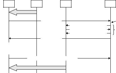
Figure 9.14 Change of serving cell for HSPA. It is assumed that both the source and target NodeB are part of the active set.
order to identify ‘costly’ UEs. The NodeB can also report the data rate, averaged over 100 ms, it actually provides for each priority class.
9.2.8Mobility
Mobility for HSDPA, that is, change of serving cell, is handled through RRC signaling using similar procedures as for dedicated channels. The basics for mobility are network-controlled handover and UE measurement reporting. Measurements are reported from the UE to the RNC, which, based on the measurements, reconfigures the UE and involved NodeBs, resulting in a change of serving cell.
Several measurement mechanisms are specified already in the first release of WCDMA and used for, for example, active set update, hard handover, and intrafrequency measurements. One example is Measurement Event 1D, ‘change of best cell,’ which is reported by the UE whenever the common-pilot strength from a neighboring cell (taking any measurement offsets into account) becomes stronger than for the current best cell. This can be used to determine when to switch the HS-DSCH serving cell as illustrated in Figure 9.14. Updates of the active set are not included in this example; it is assumed that both the source serving cell and the target serving cell are part of the active set.
The reconfiguration of the UE and involved NodeBs can be either synchronous or asynchronous. With synchronous reconfiguration, an activation time is defined in the reconfiguration message, ensuring that all involved parties change their reconfiguration at the same time. Due to unknown delays between the NodeB
High-Speed Downlink Packet Access |
163 |
and the RNC, as well as processing and protocol delays, a suitable margin may need to be taken into account in the choice of activation time. Asynchronous reconfiguration implies that the involved nodes obey the reconfiguration message as soon it is received. However, in this case, data transmission from the new cell may start before the UE has been switched from the old cell, which would result in some data loss that has to be retransmitted by the RLC protocol. Hence, synchronous reconfigurations are typically used for HS-DSCH serving cell change. The MAC-hs protocol is reset when moving from one NodeB to another. Thus the hybrid-ARQ protocol state is not transferred between the two NodeBs. Any packet losses at the time of cell change are instead handled by the RLC protocol.
Related to mobility is the flow control between the NodeB and the RNC, used to control the amount of data buffered in the MAC-hs in the NodeB and avoid overflow in the buffers. The requirements on the flow control are, to some extent, conflicting as it shall ensure that MAC-hs buffers should be large enough to contain a sufficient amount of data to fully utilize the physical channel resources (in case of advantageous channel conditions), while at the same time MAC-hs buffers should be kept as small as possible to minimize the amounts of packets that need to be resent to a new NodeB in case of inter-NodeB handover.
9.2.9 UE categories
To allow for a range of UE implementations, different UE capabilities are specified. The UE capabilities are divided into a number of parameters, which are sent from the UE at the establishment of a connection and if/when the UE capabilities are changed during an ongoing connection. The UE capabilities may then be used by the network to select a configuration that is supported by the UE. Several of the UE capabilities applicable to other channels are valid for HS-DSCH as well, but there are also some HS-DSCH-specific capabilities.
Basically, the physical-layer UE capabilities are used to limit the requirements for three different UE resources: the despreading resource, the soft-buffer memory used by the hybrid-ARQ functionality, and the Turbo decoder. The despreading resource is limited in terms of the maximum number of HS-PDSCH codes the UE simultaneously needs to despread. Three different capabilities exist in terms of de-spreading resources, corresponding to the capability to despread a maximum of 5, 10, or 15 physical channels (HS-PDSCH).
The amount of soft-buffer memory is in the range of 14 400–172 800 soft bits, depending on the UE category. Note that this is the total amount of buffer memory for all hybrid-ARQ processes, not the value per process. The memory is divided
164 |
|
|
3G Evolution: HSPA and LTE for Mobile Broadband |
|||
Table 9.1 HSDPA UE categories [99]. |
|
|
|
|
||
|
|
|
|
|
|
|
HS-DSCH |
Maximum |
Minimum |
Maximum |
Maximum |
Supported |
|
category |
number of |
inter-TTI |
transport-block size |
number of |
modulation |
|
|
HS-DSCH |
interval |
|
|
soft bits |
schemes |
|
codes received |
|
|
|
|
|
|
|
|
|
|
|
|
1 |
5 |
3 |
7298 |
(3.6 Mbit/s) |
19200 |
16QAM, QPSK |
2 |
5 |
3 |
7298 |
(3.6 Mbit/s) |
28800 |
16QAM, QPSK |
3 |
5 |
2 |
7298 |
(3.6 Mbit/s) |
28800 |
16QAM, QPSK |
4 |
5 |
2 |
7298 |
(3.6 Mbit/s) |
38400 |
16QAM, QPSK |
5 |
5 |
1 |
7298 |
(3.6 Mbit/s) |
57600 |
16QAM, QPSK |
6 |
5 |
1 |
7298 |
(3.6 Mbit/s) |
67200 |
16QAM, QPSK |
7 |
10 |
1 |
14411 |
(7.2 Mbit/s) |
115200 |
16QAM, QPSK |
8 |
10 |
1 |
14411 |
(7.2 Mbit/s) |
134400 |
16QAM, QPSK |
9 |
15 |
1 |
20251 |
(10.1 Mbit/s) |
172800 |
16QAM, QPSK |
10 |
15 |
1 |
27952 |
(14 Mbit/s) |
172800 |
16QAM, QPSK |
11 |
5 |
2 |
3630 |
(1.8 Mbit/s) |
14400 |
QPSK |
12 |
5 |
1 |
3630 |
(1.8 Mbit/s) |
28800 |
QPSK |
|
|
|
|
|
|
|
among the multiple hybrid-ARQ processes, typically with an equal amount of memory per process although non-equal allocation is also possible.
The requirements on the Turbo-decoding resource are defined through two parameters: the maximum number of transport-channel bits that can be received within an HS-DSCH TTI and the minimum inter-TTI interval, that is the distance in time between subsequent transport blocks. The decoding time in a Turbo decoder is roughly proportional to the number of information bits which thus provides a limit on the required processing speed. In addition, for low-end UEs, there is a possibility to avoid continuous data transmission by specifying an inter-TTI interval larger than one.
In order to limit the number of possible combinations of UE capabilities and to avoid parameter combinations that do not make sense, the UE capability parameters relevant for the physical layer are lumped into 12 different categories as illustrated in Table 9.1.
9.3Finer details of HSDPA
9.3.1Hybrid ARQ revisited: physical-layer processing
Hybrid ARQ with soft combining has been described above, although some details of the physical-layer and protocol operation were omitted in order to simplify the description. This section provides a more detailed description of the processing, aiming at filling the missing gaps.
High-Speed Downlink Packet Access |
165 |
First RM stage |
Virtual IR buffer Second RM stage |
|
Systematic |
Nsys |
RM_S |
Nt,sys |
|
|
bits |
|
|
|
|
|
|
|
|
|
|
Rate-1/3 |
Parity 1 |
Np1 |
RM_P1_2 |
Nt,p1 |
To physical |
Turbo |
|
RM_P1_1 |
|
channel |
|
coding |
|
|
|
|
segmentation |
|
Parity 2 |
Np 2 |
RM_P2_2 |
Nt,p2 |
and interleaving |
|
|
RM_P2_1 |
|
|
|
|
|
|
r |
s |
|
Figure 9.15 The principle of two-stage rate matching.
As already mentioned, the hybrid ARQ operates on a single transport block, that is, whenever the HS-DSCH CRC indicates an error, a retransmission representing the same information as the original transport block is requested. Since there is a single transport block per TTI, this implies that it is not possible to mix transmissions and retransmissions within the same TTI.
Since incremental redundancy is the basic hybrid-ARQ soft-combining scheme, retransmissions generally consist of a different set of coded bits. Furthermore, the modulation scheme, the channelization-code set, and the transmission power can be different compared to the original transmission. Incremental redundancy generally has better performance, especially for high initial code rates, but poses higher requirements on the soft buffering in the UE since soft bits from all transmission attempts must be buffered prior to decoding. Therefore, the NodeB needs to have knowledge about the soft-buffer size in the UE (for each active hybrid-ARQ process). Coded bits that do not fit within the soft buffer shall not be transmitted. For HSDPA, this problem is solved through the use of two-stage rate matching. The first rate-matching stage limits the number of coded bits to what is possible to fit in the soft buffer, while the second rate-matching stage generates the different redundancy versions.
Each rate-matching stage uses several identical rate-matching blocks, denoted RM in Figure 9.15. An RM block can be configured to puncture or repeat every nth bit.
The first rate-matching stage is used to limit the number of coded bits to the available UE soft buffer for the hybrid-ARQ process currently being addressed. A sufficient number of coded bits are punctured to ensure that all coded bits at the output of the first rate-matching stage will fit in the soft buffer (known as virtual IR buffer at the transmitter side). Hence, depending on the soft-buffer size in the UE, the lowest code rate may be higher than the rate-1/3 mother code rate in the Turbo coder. Note that, if the number of bits from the channel coding does not
166 |
3G Evolution: HSPA and LTE for Mobile Broadband |
exceed the UE soft-buffering capability, the first rate-matching stage is transparent and no puncturing is performed.
The second rate-matching stage serves two purposes:
•Matching the number of bits in the virtual IR buffer to the number of available channel bits. The number of available channel bits is given by the size of the channelization-code set and the modulation scheme selected for the TTI.
•Generating different sets of coded bits as controlled by the two redundancyversion parameters r and s, described below.
Equal repetition for all three streams is applied if the number of available channel bits is larger than the number of bits in the virtual IR buffer, otherwise puncturing is applied.
To support full incremental redundancy, that is, to have the possibility to transmit only/mainly parity bits in a retransmission, puncturing of systematic bits is possible as controlled by the parameter s. Setting s = 1 implies that the systematic bits are prioritized and puncturing is primarily applied with an equal amount to the two parity-bit streams. On the other hand, for a transmission prioritizing the parity bits, s = 0 and primarily the systematic bits are punctured. If, for a transmission prioritizing the systematic bits, the number of coded bits is larger than the number of physical channel bits, despite all the parity bits have been punctured, further puncturing is applied to the systematic bits. Similarly, if puncturing the systematic bits is not sufficient for a transmission prioritizing the parity bits, puncturing is applied to the parity bits as well.
For good performance, all systematic bits should be transmitted in the initial transmission, corresponding to s = 1, and the code rate should be set to less than one. For the retransmission (assuming the initial transmission did not succeed), different strategies can be applied. If the NodeB received neither ACK, nor NAK, in response to the initial transmission attempt, the UE may have missed the initial transmission. Setting s = 1 also for the retransmission is therefore appropriate. This is also the case if NAK is received and Chase combining is used for retransmissions. However, if a NAK is received and incremental redundancy is used, that is, the parity bits should be prioritized, setting s = 0 is appropriate.
The parameter r controls the puncturing pattern in each rate-matching block in Figure 9.15 and determines which bits to puncture. Typically, r = 0 is used for the initial transmission attempt. For retransmissions, the value of r is typically increased, effectively leading to a different puncturing pattern. Thus, by varying r, multiple, possibly partially overlapping, sets of coded bits representing the
High-Speed Downlink Packet Access |
167 |
2404 Transport block
CRC insertion, scrambling, rate-1/3
Turbo coding, tail inclusion
2432 |
Systematic bits |
2432
Parity bits
2432
|
First rate matching |
2432 |
|
2284 |
Virtual IR buffer |
2284 |
|
Second rate matching, |
transmissionInitial |
|
|
||
initial transmission |
|
|
Second rate matching, |
Retransmission |
|
retransmission |
||
|
2432
Soft combining in the UE
704
704
To Turbo decoder
0
1920
1920
Multiple received copies of the same coded bits are added prior to decoding (as is the case for Chase combining)
Figure 9.16 An example of the generation of different redundancy versions in the case of IR. The numbers indicate the number of bits after the different stages using the example case in the text.
same set of information bits can be generated. It should be noted that changing the number of channel bits by changing the modulation scheme or the number of channelization codes also affects which coded bits that are transmitted even if the r and s parameters are unchanged between the transmission attempts.
With the two-stage rate-matching scheme, both incremental redundancy and Chase combining can easily be supported. By setting s = 1 and r = 0 for all transmission attempts, the same set of bits is used for the retransmissions as for the original transmission, that is Chase combining. Incremental redundancy is easily achieved by setting s = 1 and using r = 0 for the initial transmission, while retransmissions use s = 0 and r >0. Partial IR, that is, incremental redundancy with the systematic bits included in each transmission, results if s = 1 for all the retransmissions as well as the initial transmission.
In Figure 9.16, a simple numerical example is shown to further illustrate the operation of the physical-layer hybrid-ARQ processing of data. Assume that, as an example, a transport block of 2404 bits is to be transmitted using one of the