

3G Evolution. HSPA and LTE for Mobile Broadband
.pdfMBMS |
249 |
Counting is a mechanism where UEs connect to the network to indicate whether they are interested in a particular service or not and is useful to determine the best transmission mechanism for a given service. For example, if only a small number of users in a cell are interested in a particular service, point-to-point transmission may be preferable over point-to-multipoint transmission. To avoid the system being heavily loaded in the uplink as a result of counting responses, only a fraction of the UEs transmit the counting information to the network. The MCCH counting information controls the probability with which a UE connects to the network to transmit counting information. Counting can thus provide the operator with valuable feedback on where and when a particular service is popular, a benefit typically not available in traditional broadcast networks.
To reduce UE power consumption and avoid having the UE constantly receiving the MCCH, a new physical channel, the MICH (MBMS Indicator Channel), is introduced to support MBMS. Its purpose is to inform UEs about upcoming changes in the critical MCCH information and the structure is identical to the paging indicator channel. In each 10 ms radio frame, 18, 36, 72, or 144 MBMS indicators can be transmitted, where an indicator is a single bit, transmitted using on–off keying and related to a specific group of services.
By exploiting the presence of the MICH, UEs can sleep and briefly wake up at predefined time intervals to check whether an MBMS indicator is transmitted. If the UE detects an MBMS indicator for a service of interest, it reads the MCCH to find the relevant control information, for example when the service will be transmitted on the MTCH. If no relevant MBMS indicator is detected, the UE may sleep until the next MICH occasion.
11.2.3MSCH
The purpose of the MSCH is to enable UEs to perform discontinuous reception of the MTCH. Its content informs the UE in which TTIs a specific service will be transmitted. One MSCH is transmitted in each S-CCPCH carrying the MTCH and the MSCH content is relevant for a certain service and a certain S-CCPCH.
252 |
3G Evolution: HSPA and LTE for Mobile Broadband |
a MIMO-capable UE will offer higher cell-edge data rates also in large cells, compared to a corresponding single-antenna UE.
The scheme used for HSDPA-MIMO is sometimes referred to as dual-stream transmit adaptive arrays (D-TxAA) [16], which is a multi-codeword scheme with rank adaptation and pre-coding. The scheme can be seen as a generalization of closed-loop mode-1 transmit diversity [97], present already in the first WCDMA release.
Transmission of up to two streams is supported by HSDPA-MIMO. Each stream is subject to the same physical-layer processing in terms of coding, spreading and modulation as the corresponding single-layer HSDPA case. After coding, spreading, and modulation, linear pre-coding is used before the result is mapped to the two transmit antennas. As discussed in Chapter 6, there are several reasons for this pre-coding. Even if only a single stream is transmitted, it can be beneficial to exploit both transmit antennas by using transmit diversity. Therefore, the precoding in the single-stream case is similar to closed-loop transmit diversity mode-1 (the difference is mainly in the details for signaling and the update rate as will be discussed below). In essence, this can be seen as a simple form of beam-forming. Furthermore, the pre-coding attempts to pre-distort the signal such that the two streams are (close to) orthogonal at the receiver. This reduces the interference between the two streams and lessens the burden on the receiver processing.
Mainly the physical-layer processing is affected by the introduction of MIMO; the impact to the protocol layer is small and MIMO is to a large extent only visible as a higher data rate.
12.1.1HSDPA-MIMO data transmission
To support dual-stream transmission, the HS-DSCH is modified to support up to two transport blocks per TTI. Each transport block represents one stream. A CRC is attached to each of the transport blocks and each transport block is individually coded. This is illustrated in Figure 12.1 (compare with Chapter 9 for the non-MIMO case). Since two transport blocks are used in case of multi-stream transmission, HSDPA-MIMO is a multi-codeword scheme (see Chapter 6 for a discussion on single vs multi-codeword schemes) and allows for a successive-interference-cancellation receiver in the UE.
The physical-layer processing for each stream is identical to the single-stream case, up to and including spreading [95, 96]. To avoid wasting channelizationcode resources, the same set of channelization codes should be used for the two streams. At the receiver, the two streams are separated by the appropriate receiver processing, for example by interference cancellation (see Chapter 6).
254 |
|
|
|
|
|
|
|
|
|
|
|
|
|
|
|
|
3G Evolution: HSPA and LTE for Mobile Broadband |
||||||||||||||
Stream 1 |
|
|
|
|
|
|
|
|
|
|
Stream 2 |
|
|
|
|
|
|
|
|
|
|
||||||||||
|
|
|
|
|
|
|
|
|
|
|
|
|
|
|
|
|
|
|
|
||||||||||||
|
|
|
|
|
|
|
|
|
|
|
|
|
|
|
|
|
|
|
|
|
|
|
|
|
|||||||
|
|
|
|
|
|
|
|
|
|
|
|
|
|
|
|
|
|
|
|
|
|
|
|
|
|
|
|
|
|
|
|
|
|
|
|
|
|
|
|
|
|
|
|
|
|
|
|
|
|
|
|
|
|
|
|
|
|
|
|
|
|
|
|
|
|
|
|
Modulation |
|
|
|
|
|
|
|
|
|
|
|
|
|
|
|
|
|
|
|
||||||||
|
|
|
|
|
|
|
|
|
|
|
|
|
|
|
|
|
|
|
|
|
|
Channelization codes |
|
|
|||||||
|
|
|
|
|
|
|
|
|
|
|
|
|
|
|
|
|
|
|
|
|
|
|
|
||||||||
|
|
|
|
|
|
|
|
|
|
|
|
|
|
|
|
|
|
|
|
|
|
|
|
||||||||
|
|
|
|
|
|
|
|
|
|
|
|
|
|
|
|
|
|
|
|
|
|
|
|
||||||||
|
|
|
|
|
|
|
|
|
|
|
|
|
|
|
|
|
|
|
|
|
|
|
|
||||||||
|
|
|
|
Spreading |
|
|
|
|
|
|
|
|
|
|
|
|
SF 16 |
|
|
|
|
||||||||||
|
|
|
|
|
|
|
|
|
|
|
|
|
|
|
|
|
|
|
|
|
|
|
|
|
|
|
|
|
|
|
|
|
|
|
|
|
|
|
|
|
|
|
|
|
|
|
|
|
|
|
|
|
|
|
|
|
|
|
|
|
|
|
|
|
|
|
|
|
|
|
+ + |
|
|
|
|
|
|
|
|
|
|
|
|
|
|
|
|
|
|
|
|
||||
|
|
|
|
|
|
|
|
|
|
|
|
|
|
|
|
|
|
|
|
|
|
|
|
|
|
|
|
|
|
|
|
|
|
|
|
|
|
|
|
|
|
|
|
|
|
|
|
|
|
|
|
|
|
|
|
|
|
|
|
|
|
|
|
|
|
|
Scrambling |
|
|
|
|
|
|
|
|
|
|
|
|
|
|
|
|
|
|
|
|||||||||
|
|
|
|
|
|
|
|
|
|
|
|
|
|
|
|
|
|
|
|
|
|
|
Virtual antennas |
|
|
|
|||||
|
|
|
|
|
|
|
x1 |
|
|
x2 |
|
|
|
|
|
|
|
|
|||||||||||||
|
|
|
|
|
|
|
|
|
|
|
|
|
|
|
|
|
|
|
|
|
|
|
|
||||||||
|
|
|
|
|
|
|
|
|
|
|
|
|
|
|
|
|
|
|
|
|
|
|
|
Pre-coding |
|
|
|
|
|||
|
|
|
|
|
|
|
|
|
w1,2 |
|
|
|
|
|
w2,2 |
|
|
y1 |
|
|
w1,1 |
w1,2 |
|
x1 |
|
||||||
|
|
|
|
|
|
|
|
|
|
|
|
|
|
|
|
||||||||||||||||
|
|
|
|
|
|
|
|
|
y2 |
|
w2,1 |
w2,2 |
x2 |
|
|||||||||||||||||
|
|
|
|
|
|
|
|
|
|
|
|
|
|
|
|
|
|
|
|||||||||||||
|
|
|
|
|
|
|
|
w1,1 |
|
|
|
|
|
|
w2,1 |
|
Common pilot 1 |
|
|
|
|||||||||||
|
|
|
|
|
|
|
|
|
|
|
|
|
|
|
|
|
|||||||||||||||
|
|
|
|
|
|
|
|
|
|
|
|
|
|
|
|
|
|
|
|
|
|
|
|
|
|
||||||
|
|
|
|
|
|
|
|
|
|
|
|
|
|
Common pilot 2 |
|
|
|
||||||||||||||
|
|
|
|
|
|
|
|
|
|
|
|
|
|
|
|||||||||||||||||
|
|
|
|
|
|
|
|
|
|
|
|
|
|
|
|
|
|
|
|
|
|
|
|
|
|
||||||
|
y1 |
|
|
|
|
|
|
|
y2 |
|
|
|
|
|
|
|
|
|
|
|
|
|
|
|
|
|
|||||
|
|
|
|
|
|
|
|
|
|
|
|
|
|
|
|
|
|
|
|
|
|
|
|||||||||
Physical |
|
Physical |
|
|
|
|
|
|
|
|
|
|
|||||||||||||||||||
antenna 1 |
antenna 2 |
|
|
|
|
|
|
|
|
|
|
||||||||||||||||||||
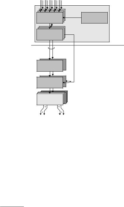
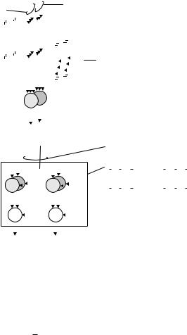
Figure 12.2 Modulation, spreading, scrambling and pre-coding for two dual-stream MIMO.
is used for each physical antenna, pre-coding ensures both of them are used also in case of single-stream transmissions, thereby increasing the total transmit power. The pre-coding weights in case of single-stream transmission are chose to be
identical to those used for Release 99 closed-loop transmit diversity,
√
w1,1 = 1/ 2,
|
2,1 |
2 |
|
2 |
|
|
− |
2+ |
|
|
|
− |
2− |
|
|
|
w |
|
(1 + j) |
, |
(1 − j) |
, |
( |
|
1 |
j) |
, |
( |
|
1 |
j) |
. |
(4.1) |
|
|
|
|
|
|
|
|
|
|
|
In case of dual-stream transmission, pre-coding can be used to aid the receiver in separating the two streams. If the weights for the second stream are chosen as the (orthogonal) eigenvectors of the covariance matrix at the receiver, the two streams will not interfere with each other at the transmitter. Hence, once the weights for the first stream are selected, the weights w1,2, w2,2 used for the second stream are given by the requirement to make the columns of the pre-coding matrix orthogonal.
w1,1 |
w1,2 |
|
|
W = w2,1 |
w2,2 |
(4.2) |
As there are four different values possible for w2,1, it follows that there are four different values of pre-coding matrix W possible. The pre-coding matrix is constant over one subframe. The setting of the weights are up to the NodeB
HSPA Evolution |
255 |
implementation but is typically based on Pre-coding Control Indication (PCI) feedback from the UE.
To demodulate the transmitted data, the UE requires estimates of the channels between each of the base station virtual antennas and each of UEs physical antennas. Hence, a total of four channels need to be estimated. One possibility would be to transmit a common pilot signal on each of the virtual antennas. However, this would not be backwards compatible as UEs assume the primary common pilot to be transmitted from the primary antenna. Demodulation of non-MIMO channels, for example the control channels necessary for the operation of the system, would not be possible either as these channels are not transmitted using any pre-coding. Therefore, the common pilot channels are transmitted in the same way as for transmit diversity. On each physical antenna, a common pilot channel is transmitted. Either a primary common pilot channel is configured on each antenna, using the same channelization and scrambling code on all antennas, or a primary common pilot is configured on one antenna and a secondary common pilot on the other antenna. In case a primary common pilot is configured on both antennas, different mutually orthogonal pilot patterns are used on the different common pilots (all zeros for the first physical antenna as in the single-antenna case, and a sequence of zero and ones for the second physical antenna). Both these schemes enable the UE to estimate the channel from each of the physical transmit antennas to each of its receive antennas. Given knowledge of the pre-coding matrix the NodeB used, the UE can form an estimate of the effective channel from each of the virtual antennas
ˆ
to each of the physical receiver antennas as HW, where
|
|
h |
h |
|
|
Hˆ |
= |
ˆ 1,1 |
ˆ 1,2 |
|
(4.3) |
h2,1 |
h2,2 |
||||
|
|
ˆ |
ˆ |
|
|
ˆ i,j is the estimate of the channel between the physical antenna i at the base and h
station and the physical antenna j at the UE. For this reason, the pre-coding matrix is signaled to the UE on the HS-SCCH. Explicit signaling of the pre-coding matrix greatly simplifies the UE implementation compared to estimation of the antenna weights which is the case for closed-loop transmit diversity in Release 99 [97].
12.1.2Rate control for HSDPA-MIMO
Rate control for each stream is similar to the single-stream case. However, the rate-control mechanism also needs to determine the number of streams to transmit and the pre-coding matrix to use. Hence, for each TTI, the number of streams to transmit, the transport-block sizes for each of the streams, the number of channelization codes, the modulation scheme, and the pre-coding matrix is determined by the rate-control mechanism. This information is provided to the UE on the HS-SCCH, similar to the non-MIMO case. As the scheduler controls the size of

256 |
3G Evolution: HSPA and LTE for Mobile Broadband |
the two transport blocks in case of multi-stream transmission, the data rate of the two streams can be individually controlled.
Multi-stream transmission is beneficial only at relatively high carrier-to- interference ratios and will consequently only be used for the highest data rates. For lower data rates, single-stream transmission should be used. In this case, the two physical antennas are used for diversity transmission and only one of the virtual antennas is carrying user data.
Similar to Release 6, the rate-control mechanism typically relies on UE feedback of the instantaneous channel quality. In case of dual-stream transmission, information about the supported data rate on each of the streams is required. However, as the NodeB scheduler is free to select the number of streams transmitted to a UE, the supported data rate in case of single-stream transmission is also of interest. The CQI reports are therefore extended to cover both these cases, as well as indicating the preferred pre-coding matrix.
12.1.3Hybrid ARQ with soft combining for HSDPA-MIMO
For each stream, the physical-layer hybrid-ARQ processing and the use of multiple hybrid-ARQ processes are identical to the single-stream case. However, as the multiple streams are transmitted over different antennas, one stream may be correctly received while another stream require retransmission of the payload.2 Therefore, one ACK/NAK per stream is sent from the UE to the NodeB.
12.1.4Control signaling for HSDPA-MIMO
To support MIMO, the out-band control signaling is modified accordingly. No changes to the in-band control signaling in the form of the MAC-hs header are required as reordering and priority queue selection is not affected by the introduction of MIMO. However, to efficiently support the higher data rates provided by MIMO, the MAC, and RLC layers are updated with flexible segmentation.
The downlink out-band control signaling is carried on the HS-SCCH. In case MIMO support is enabled in the UE, an alternative format of the HS-SCCH is used to accommodate the additional information required (Figure 12.3). The division of the HS-SCCH into two parts (see Chapter 9) is maintained. Part one is extended to include information about the number of streams transmitted to the UE, one or two, and their respective modulation scheme as well as which of the four pre-coding matrices the NodeB used for the transmission. For the second part of the HSSCCH, the format used depends on whether one or two streams were scheduled
2 Typically, if the first stream is erroneously received, decoding of the second stream is likely to fail if successive interference cancellation is used.

258 |
3G Evolution: HSPA and LTE for Mobile Broadband |
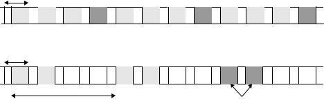
N/M 3/4, 2ms reporting cycle, no repetition
2 ms subframe
A 
 A
A 
 A
A 
 B
B 
 A
A 
 A
A 
 A
A 
 B
B 
 A
A 
 A
A 
 A
A 
 B
B
N/M 2/3, 8ms reporting cycle, repetition factor 2
2 ms subframe
A |
A |
A |
A |
B |
B |
8 ms reporting cycle
Repetition
Figure 12.4 Example of type A and type B PCI/CQI reporting for a UE configured for MIMO reception.
Table 12.1 Peak data rates with MIMO.
HS-DSCH |
Max number |
Modulation |
Max data rate |
||
category |
of codes |
schemes |
|
|
|
Single stream |
Dual stream |
||||
|
|
|
|||
|
|
|
|
|
|
9 |
15 |
16QAM, QPSK |
11.7 Mbit/s |
23.4 Mbit/s |
|
10 |
|
|
14 Mbit/s |
28 Mbit/s |
|
|
|
|
|
|
|
Similar to the non-MIMO case, the PCI/CQI reports are transmitted in two slots on the HS-DPCCH. To allow for a flexible adaptation to different propagation environments, the first N out of M PCI/CQI reports are type A reports and the remaining M–N reports are type B reports. The ratio N/M is configured by RRC signaling. Two examples are shown in Figure 12.4.
12.1.5UE capabilities
To allow for a wide range of different UE implementations, MIMO support is not mandatory for all UEs. Furthermore, as multi-stream transmission mainly is a tool for increasing the supported peak data rates, MIMO is mainly relevant for the high-end UE categories. Therefore, a UE supporting MIMO is either a category 9 or category 10 UE [99]. Whether a particular UE is capable of MIMO or not is signaled as a separate UE capability; as an example a terminal can be category 9 when operating in MIMO mode and category 10 otherwise. If MIMO is not configured in an MIMO-capable terminal, the behavior is identical to that of Release 6.
The supported data rates with and without MIMO for these UEs are listed in Table 12.1. Note that the peak data rate for MIMO-capable category 9 UEs in case of single-stream transmission is slightly higher than the corresponding non-MIMO UEs.
