

3G Evolution. HSPA and LTE for Mobile Broadband
.pdf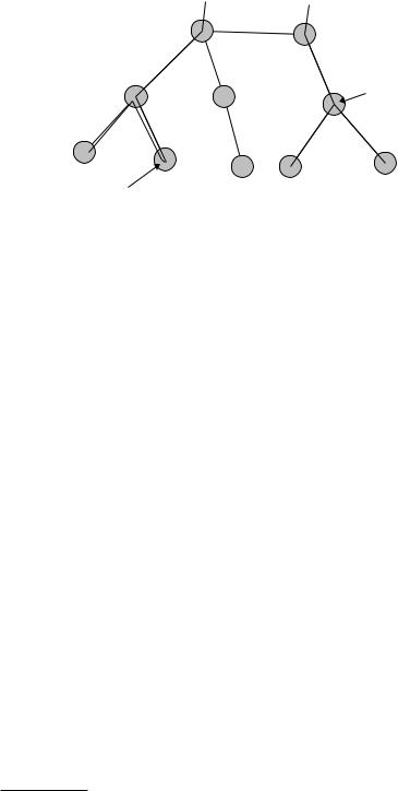
System Architecture Evolution |
375 |
Macro-diversity in an aggregation node
Macro-diversity in a leaf node
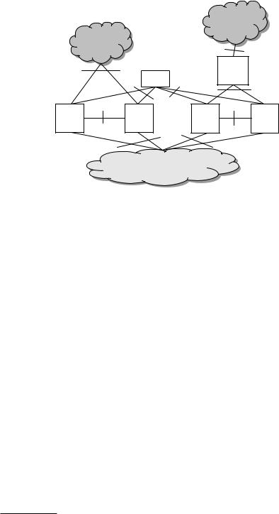
Figure 18.2 Transport network topology influencing functional allocation.
in Chapter 8, macro-diversity requires an anchor point in the RAN1 that splits and combines data flows to and from cells that the terminals are currently using. Those cells are called the active set of the terminal.
While it is perfectly possible to have the anchor in the node that connects to the antenna of one cell and have the other cells data flow go through that node, it is not desirable from a transport-network point of view. Most radio-access networks have transport-network limitations, mainly in the last mile, that is the last hop to the antenna site. Furthermore, the antenna sites are normally leafs in a tree branch and hence an anchor in a leaf often implies that the last mile have to be traversed several times as illustrated in Figure 18.2. Due to this fact, the anchor point was specified to be in a separate node from the node connecting the antenna.
As a consequence of locating the macro-diversity combining above the node connecting to the antenna, the link layer needs to terminate in the same node as the macro-diversity or in a node higher up in the RAN hierarchy. Since the only reason for terminating the link layer in another node than the macro-diversity combining node would be to save transport resources, and having them separated would cause significant complexity, it was decided to have them in the same node. With the same reasoning also the control plane signaling of the RAN was located in the node doing the macro-diversity. The node was named Radio Network Controller (RNC), since it basically controls the RAN.
Although macro-diversity is not used for HSPA in the downlink, it is used in the uplink. This fact and the principle that the architecture also shall support WCDMA
1 It is fundamentally possible to locate the macro-diversity function in the core network, but since that was against the RAN/CN functional split design philosophy it was never considered.
376 |
|
|
3G Evolution: HSPA and LTE for Mobile Broadband |
|
|
|
Core network |
|
|
|
|
Iu |
Iu |
|
|
RNC |
|
|
RNC |
|
|
|
Iur |
|
Iub |
|
Iub |
Iub |
Iub |
|
|
|||
|
|
|
||
|
Iub |
|
|
|
NodeB |
NodeB |
NodeB |
NodeB |
NodeB |
Cell Cell |
Cell Cell |
Cell |
Cell Cell Cell |
Cell Cell Cell Cell |
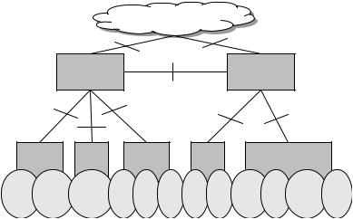
Figure 18.3 WCDMA/HSPA radio access network: nodes and interfaces.
Release 99 with minimum changes leads to the RNC being present also in the WCDMA/HSPA architecture.
Figure 18.3 shows an overview of the WCDMA/HSPA radio access network. As can be seen in the figure, the RAN consists of two fundamental logical nodes: the RNC and the node connecting to the antenna of the cells, the NodeB.
The RNC is the node connecting the RAN to the core network via the Iu interface. The principle of the Iu interface is that it should be possible to use it toward different RANs, not only WCDMA/HSPA RAN.
Each RNC in the network can connect to every other RNC in the same network using the Iur interface. Thus, the Iur interface is a network wide interface making it possible to keep one RNC as an anchor point for a terminal and hide mobility from the core network. Furthermore, the Iur interface is necessary to be able to perform macro-diversity between cells belonging to different RNCs.
As can be seen from Figure 18.3, one RNC connects to one or more NodeBs using the Iub interface. However, in contrast to the fact that one RNC can connect to any other RNC in the network, one NodeB can only connect to one RNC. Thus only one RNC is controlling the NodeB. This means that the RNC owns the radio resources of the NodeB. In case of a macro-diversity connection across RNCs, the two RNCs agree between themselves about the use of the radio resources.
The NodeB is a logical node handling the transmission and reception of a set of cells. Logically, the antennas of the cells belong to the NodeB but they are not

378 |
3G Evolution: HSPA and LTE for Mobile Broadband |
deciding which cell(s) should be part of the terminals active set.3 Furthermore, the serving RNC sets the quality targets of the terminal and it is the RNC that connects the user to the core network. It is also the serving RNC that configures the terminal with radio-bearer configurations enabling the different services that the user wishes to use.
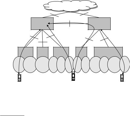
During the connection, the terminal may move and at some point may need to connect to another cell that belongs to another RNC. In such case, the serving RNC of the terminal needs to contact the RNC owning the cell the terminal intends to use, asking for permission to add the new cell to the active set. If the controlling RNC owning the (target) cell accepts, the serving RNC instructs the terminal that it shall add the cell to its active set. The controlling RNC owning the target cell will then become a drift RNC. It should be noted that a drift RNC can be a serving RNC for another terminal at the same time. Thus, serving and drift are two different roles an RNC can take in a connection to a terminal. The serving and drift roles are illustrated in Figure 18.4. When a terminal has a long-lived connection it is possible that the serving RNC does not control any of the cells that the terminal is
|
|
Core network |
|
|
|
RNC1 |
Iu |
Iu |
RNC2 |
|
|
|
||
|
SRNC |
|
|
DRNC |
|
SRNC |
Iur |
|
SRNC |
|
|
|
|
|
Iub |
|
Iub |
Iub |
Iub |
|
|
|||
|
|
|
||
|
|
Iub |
|
|
NodeB |
NodeB |
NodeB |
NodeB |
NodeB |
Cell Cell |
Cell |
Cell Cell Cell |
Cell Cell |
Cell Cell Cell Cell |
Figure 18.4 Roles of the RNC. RNC1 is controlling RNC of the NodeBs and cells that are connected to it via Iub interfaces. RNC1 is Serving RNC for the leftmost terminal and the middle terminal. RNC2 is controlling RNC for the NodeBs and cells that are connected to it via Iub interfaces. RNC2 is Serving RNC for the rightmost terminal and at the same time Drift RNC for the middle terminal.
3 The active set is a set of cells that the terminal is active in. When using dedicated channels all the cells are sending and receiving the DL and the UL transmissions, respectively.

System Architecture Evolution |
379 |
currently using. In such case, it is possible to change serving RNC. This is done by means of the SRNS relocation procedure.4
For the MBMS service, the RNC takes a special role. It is the RNC that decides whether to use broadcast channels in a cell or to use unicast channels. When using unicast channels, the operation is as for normal unicast traffic whereas when using the broadcast channel the RNC has the option to ensure that the same data is transmitted in the surrounding cells owned by the same RNC. By doing that, the terminal can perform macro-diversity combining of the streams from the different cells and the system throughput can be increased.
The basis whether to use unicast or broadcast for MBMS in a cell is typically based on the number of mobile terminals supposed to receive the same content at the same time in the same cell. If there are few users in the cell a unicast approach is more efficient whereas if there are many users in the cell (or in the surroundings of the cell), it is more efficient to use the broadcast channel. The techniques used for the MBMS broadcast channel were discussed in Chapter 11.
18.2.1.2Architecture of HSPA evolution
3GPP is considering possible RAN architecture migration steps toward a flatter architecture. Several proposals exist. One simple proposal is to move the complete RNC to the NodeB. This is in principle already possible with the Release 99 architecture, but with a few issues:
•The number of RNCs is limited to 4096 on the Iu interface. This will be extended and is thus not regarded as any big problem.
•A more significant issue is the location of the security functions at the NodeB site. The NodeB site is normally considered as an unsecured and remote site. Having the security functions in the NodeB means that important and confidential cryptographic keys need to be transported to the NodeB. This is done over the last mile and it can easily be eavesdropped. Thus also the last mile needs to be secured by some security mechanism, for example IPsec. However, this is not sufficient to make the connection secure as also the equipment itself needs to be tamper resistant. This can make the solution complex and expensive. Thus if the operator know that the NodeB is at a secure site, then the operator can deploy a network with NodeBs and RNCs colocated (or with products that have them implemented in the same physical equipment). For sites not secure enough, the operator may use the conventional solution with an RNC at a secure site higher up in the network and a NodeB at the vulnerable site.
4 The SRNS relocation procedure is not further elaborated upon in this book. Interested readers are referred to 3GPP TS 25.413 [104] and TR 25.832 [83].

380 |
3G Evolution: HSPA and LTE for Mobile Broadband |
•A third issue with the RNC functionality at the NodeB site is the macro-diversity functionality needed for the HSPA uplink to reach good capacity and quality. As discussed in Section 18.2.1, the macro-diversity location is often better located ‘higher’ up in the network.
In any case, the most important requirement on the RAN architecture for HSPA Evolution is to be able to serve legacy traffic and cooperate with legacy nodes (RNCs and NodeBs). Thus, the Release 99 architecture is a valid architecture also for HSPA Evolution. Furthermore, as discussed above, the possibility of a flatter deployment exist also in this architecture.
18.2.2LTE radio access network
At the time of adopting the single-node architecture for LTE, the function of macro-diversity was heavily discussed in 3GPP. Although it is technically possible to place the macro-diversity functionality in the corresponding LTE node to a WCDMA/HSPA NodeB, the eNodeB, and have one of those nodes as an anchor, the fundamental need for macro-diversity for LTE was questioned. Quite quickly it was decided that downlink macro-diversity is not needed for unicast traffic but the uplink was heavily debated. In the end it was decided that uplink macro-diversity does not give the gains for LTE that motivates the complexity increase. Thus, macro-diversity between eNodeBs is not supported in LTE.
For broadcast and multicast traffic it was decided very early that the eNodeBs need to be capable of transmitting the same data in a synchronized manner in order to support MBSFN operation. The needed synchronization is within micro-seconds as discussed in Chapter 16.
At first, it may seem obvious to move all the RAN functionality to the eNodeB when not supporting macro-diversity. However, terminal mobility needs to be considered as well. There are basically two issues with mobility that need attention: guarantee of no loss of data when changing cell and minimizing the core network impact when changing cell. For LTE, the latter was not considered as a major problem; proper design of the core network will solve the issue. The former was, however, a more difficult problem to solve. It was in fact agreed that having a centralized anchor with a retransmission layer outside the eNodeB would make it easier for mobility. However, 3GPP decided that the added complexity with not having the anchor was better than requiring a node with RAN functionality outside the eNodeB.5
5 There was a proposal where the retransmission functionality was located in the core network and not in the RAN to minimize the number of nodes. This was rejected due to the principle of keeping radio functions in the RAN.
System Architecture Evolution |
381 |
Core network
|
S1 |
S1 |
|
|
S1 |
S1 |
|
|
S1 |
|
|
||
|
|
|
|
|
|
|
X2 |
eNodeB |
X2 |
|
X2 |
eNodeB |
X2 |
eNodeB |
|
eNodeB |
eNodeB |
|||
Cell Cell |
Cell |
Cell Cell |
Cell |
Cell Cell |
Cell Cell Cell Cell |
|
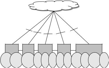
Figure 18.5 LTE radio access network: nodes and interfaces.
Figure 18.5 shows an overview of the LTE radio access network with its nodes and interfaces. Contrary to the WCDMA/HSPA RAN, the LTE RAN only has one node type: the eNodeB. Thus, there is no equivalent node to an RNC for LTE. The main reason for this is that there is no support for uplink or downlink macro-diversity for dedicated user traffic and the design philosophy of minimizing the number of nodes.
The eNodeB is in charge of a set of cells. Similar to the NodeB in the WCDMA/ HSPA architecture, the cells of an eNodeB do not need to be using the same antenna site. Since the eNodeB has inherited most of the RNC functionality, the eNodeB is a more complicated node than the NodeB. The eNodeB is in charge of single cell RRM decisions, handover decisions, scheduling of users in both uplink and downlink in its cells, etc.
The eNodeB is connected to the core network using the S1 interface. The S1 interface is a similar interface as the Iu interface. There is also an interface similar to the Iur interface of WCDMA/HSPA, the X2 interface. The X2 interface connects any eNodeB in the network with any other eNodeB. However, since the mobility mechanism for LTE is somewhat different compared to WCDMA/HSPA as there is no anchor point in the LTE RAN, the X2 interface will only be used between eNodeBs that has neighboring cells.
The X2 interface is mainly used to support active-mode mobility. This interface may also be used for multi-cell Radio Resource Management (RRM) functions. The X2 control-plane interface is similar to its counter part of WCDMA/HSPA, the Iur interface, but it lacks the RNC drift-functionality support. Instead, it provides the eNodeB relocation functionality support. The X2 user plane interface is used to support loss-less mobility (packet forwarding).
382 |
3G Evolution: HSPA and LTE for Mobile Broadband |
18.2.2.1 eNodeB roles and functionality
The eNodeB has the same functionality as the NodeB and in addition, it has most of the WCDMA/HSPA RNC functionality. Thus, the eNodeB is in charge of the radio resources in its cells, it decides about handover, makes the scheduling decisions for both uplink and downlink. Obviously, it also performs the classical physical layer functions of coding, decoding, modulation, demodulation, interleaving, de-interleaving, etc. Furthermore, the eNodeB hosts the two layer retransmission mechanisms; the hybrid ARQ and an outer ARQ as described in Chapter 15.
Since the handover mechanism of LTE is different from WCDMA/HSPA, there is no other role of the eNodeB than serving eNodeB. The serving eNodeB is the eNodeB that serves the terminal. The concepts of controlling and drift do not exist. Instead the handover is done by means of eNodeB relocations.
For MBMS type of traffic the LTE RAN decides whether to use unicast or broadcast channels as is the case for WCDMA/HSPA. In case of broadcast channels, the coverage and capacity of those increases significantly if MBSFN operation can be used as described in Chapter 4. In order for the eNodeBs to be able to send the data streams simultaneously, an MBMS Coordination Entity (MCE) synchronizes the eNodeB transmissions and data streams. The synchronization is done via a global clock, for example GPS.
18.3Core network architecture
As discussed previously in this chapter, the mobile system needs a core network to perform the core network functionality. At the same time as the RAN-internal architecture was discussed in 3GPP, the core network architecture was also discussed. Contrary to starting from scratch with both the WCDMA/HSPA RAN and the LTE RAN, the core network used for WCDMA/HSPA and LTE is based on an evolution from the GSM/GPRS core network. The core network used for WCDMA/HSPA is very close to the original core network of GSM/GPRS except for the difference in the functional split with the GSM RAN. The core network used to connect to the LTE RAN is however a more radical evolution of the GSM/GPRS core network. It has therefore got its own name: the Evolved Packet Core (EPC).
18.3.1GSM core network used for WCDMA/HSPA
For WCDMA/HSPA, the core network is based on the GSM core network with the same nodes as for GSM. As discussed in Section 18.1.1, the functional split of GSM and WCDMA/HSPA is different. This led to the use of a different interface between the core network and the WCDMA/HSPA RAN compared to between the core network and the GSM RAN. For WCDMA/HSPA the Iu interface is used, whereas for GSM the A and Gb interfaces are used.
System Architecture Evolution |
383 |
|
|
|
Internet |
|
PSTN |
|
Gi |
|
|
|
|
|
|
HLR |
GGSN |
|
C&D |
Gn/Gp |
|
|
|
|
|
|
|
Gr |
|
MSC |
MSC |
SGSN |
SGSN |
|
E&Nb&Nc |
Iu_ps |
Gn |
|
|
|
|
|
Iu_cs |
|
|
|
|
RAN |
|
Figure 18.6 Overview of GSM and WCDMA/HSPA core network – somewhat simplified figure.
Figure 18.6 shows an overview of the core network architecture6 used for WCDMA/HSPA. The figure shows a logical view and as always when it comes to architecture, that does not necessarily translates into physical entities. The core network consists of two distinct domains:
1.the Circuit-Switched (CS) domain with the Mobile Switching Centre (MSC);
2.the Packet-Switched (PS) domain with the Serving GPRS Support Node (SGSN) and Gateway GPRS Support Node (GGSN).
Common for the two domains is the Home Location Register (HLR), a data base in the home operator’s network keeping track of the subscribers of that operator. As can be seen in the figure, the Iu interface is connecting the WCDMA/HSPA RAN to the MSC via the Iu_cs interface and to the SGSN via the Iu_ps interface. Not visible in the figure is that the A interface connects the MSC and the Gb connects the SGSN to the GSM RAN.
The Iu-cs is used to connect the RNC of WCDMA/HSPA to the circuit switch domain of the core network, i.e. to the MSC. The MSC is used for connecting phone calls to Public Switched Telecommunications Networks (PSTN). The MSC and the circuit-switched domain use the functions from the Integrated Service Digital Network (ISDN) as switching mechanism. Thus, the signaling to the MSC is based on ISDN.
6 The figure shows a simplified view of the core network. The interested reader is referred to [89] and [90] for more detailed information.