

3G Evolution. HSPA and LTE for Mobile Broadband
.pdf384 |
3G Evolution: HSPA and LTE for Mobile Broadband |
The Iu-PS interface is used to connect the RNC to the packet-switch domain of the core network, that is the SGSN. The SGSN is in turn connected to a GGSN via a Gn or Gp interface. The GGSN is then having a Gi interface out to external packet networks (for example the Internet), to the operator’s service domain or the IP Multimedia Subsystem (IMS). The packet-switch domain is using IP routing.
Common for both CS and PS domain is the HLR, which is a database in the home operator’s network keeping track of the subscribers of that operator. The HLR contains information about subscribed services, current location of the subscriber’s Subscriber Identity Module (SIM)/UMTS SIM (USIM) card (that is in which location and routing area the terminal that the SIM/USIM is attached to currently is registered to be in), etc. The HLR is connected to the MSC via the C and D interfaces, and to the SGSN via the Gr interface.
18.3.1.1 Iu flex
The Iu interface supports a function called Iu flex. This function allows one RNC to connect to more than one SGSN or MSC and vice versa. This function is useful to reduce the effects if one of the core network nodes is unavailable, that is an SGSN or MSC is not working properly. The Iu flex mechanism is used to distribute the terminal connections over several SGSNs and MSCs. If one SGSN or MSC is unavailable, the other SGSNs and MSCs keep their allocated traffic and can take all the incoming calls or packet session setup requests (many incoming calls are expected when a core network node becomes unavailable, since most terminals will try to reconnect when they are disconnected without warning).
18.3.1.2 MBMS and other broadcast
For MBMS, the packet-switched domain of the core network is used. Consequently the Iu_ps interface is used to connect to the WCDMA/HSPA RAN. For MBMS, it is the core network that decides whether to use broadcast bearer or a multicast bearer. In case of broadcast bearers, the core network does not know the identity of mobile terminals receiving the information, whereas for the multicast bearers this is known to the core network. Thus the terminals do not need to inform the core network of their intentions when receiving a service that uses broadcast bearer, whereas when receiving a service that is using a multicast bearer the terminals need to inform the core network of its intention to use the service.
For both multicast and broadcast MBMS bearers, the RAN can decide whether to use unicast transport channels or a broadcast transport channel in a cell. This is done by means of the counting procedure, briefly mentioned in Chapter 11. Essentially, the RAN asks the users in a cell to inform it if the user is interested in a specific service. Then if sufficient amount of users is interested the broadcast transport channel is selected otherwise unicast transport channels are used.
System Architecture Evolution |
385 |
18.3.1.3Roaming
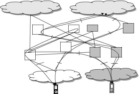
It is the roaming functionalities of the core network that makes it possible for a user to use another operator’s network. Roaming is supported both for the circuitswitched domain and the packet-switched domain. For both domains, different possibilities exist, but in practice traffic is routed via the home operators GGSN for the PS domain. For the CS domain, the common case for terminal-originated calls (outgoing calls) is to do the switching in the visited network. For terminalterminated calls (incoming calls), the call is always routed through the home network. This is illustrated in Figure 18.7. In the figure, two terminals belonging to two different operators (A and B) are shown. The terminals are roaming in the network of the other operator (bright and dark networks in Figure 18.7) and both terminals have packet-switched connections. Furthermore, the A terminal is calling the B terminal via the circuit-switched domain. As can be seen in Figure 18.7 the packet-switched connections are routed from the SGSN in the visited network to the GGSN in the home network using the Gp interface (the Gn interface are used between SGSN and GGSN in the same network whereas the Gp interface is used between SGSN and GGSN in different networks). For the circuit-switched call, the A terminal, which is originating the call, connects to the (bright) MSC of the visited network. The MSC realize that the called terminal belongs to its network and therefore contacts the bright HLR. The bright HLR responds with information that the B terminal is served by the dark MSC in the dark network. The bright MSC then contacts the dark MSC which sets up a connection to the B terminal.
18.3.1.4Charging and policy control
Charging, a for the operator important function, is located in the core network. For the circuit-switched domain it is in the MSC, whereas for the packet-switched domain it is handled either in the SGSN or in the GGSN. Traditionally, it has been possible to do charging by minutes used and charging by volume. The former commonly used for the circuit-switched domain whereas the latter is more commonly used in the packet-switched domain. However, other charging principles are also possible, for example flat rate with or without opening tariffs. Different tariffs are used depending on the subscriber’s subscription and whether the user is roaming or not. With GGSN handling the charging for packet-switched services, more advanced charging schemes, for example contentor event-based charging is supported. This allows the operator to charge the end users depending on the service used.
Policy control is a function in the core network used to control the usage of packetswitched services, that is to ensure that the user does not use more bandwidth than allowed or that the user only is accessing ‘approved’ services or web sites. The
386 |
3G Evolution: HSPA and LTE for Mobile Broadband |
||
PSTN |
|
Internet |
|
|
|
Gi |
|
|
|
|
Gi |
GGSN |
HLR1 |
HLR2 |
GGSN |
|
Gp |
|
|
|
|
|
Gp |
|
SGSN |
|
|
MSC |
|
MSC |
SGSN |
|
E |
|
|
Iu-cs |
|
|
|
|
|
|
|
|
Iu-ps |
Iu-cs |
Iu-ps |
|
RAN1 |
|
RAN2 |
|
|
|
|
|
A |
B |
|
|
|
|
|
Figure 18.7 Roaming in GSM/ and WCDMA/HSPA.
policy control is effectuated in the GGSN and it exists only in the packet-switched domain.
18.3.2 The ‘SAE’ core network: the Evolved Packet Core
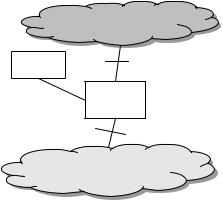
When the LTE RAN standardization was started, the corresponding work was started for the core network. This work was called the System Architecture Evolution (SAE). The core network defined in the SAE work is a radical evolution from the GSM/GPRS core network and therefore it has got a new name, Evolved Packet Core (EPC). The SAE scope only covers the packet-switched domain, not the circuit-switched domain. Looking back at the discussions in standardization, the philosophy of minimizing the number of nodes also reigns in the core network standardization. As a consequence, the Evolved Packet Core network started off as single-node architecture with all the functions in one node, except the Home Subscriber Server (HSS) which were kept outside the node. HSS is a node/database corresponding to the HLR in GSM/WCDMA core network. Figure 18.8 illustrates how the Evolved Packet Core fits into the total architecture. In Figure 18.8 and in the remainder of this book, the Evolved Packet Core is shown and discussed as one logical entity (EPC). This simplifies the illustrations and understanding of the connection to the LTE RAN and the WCDMA/HSPA network. The EPC connects to the LTE RAN via the S1 interface and to internet via the SGi interface. Furthermore, the EPC connects to the HSS using the S6 interface.
System Architecture Evolution |
|
387 |
|
|
Internet |
|
HSS |
SGi |
|
|
S6 
EPC
S1
RAN
Figure 18.8 Overview of SAE core network – simplified figure.
S1 is the interface between eNodeBs and EPC. The S1 interface is very similar to the Iu_ps interface. The S1 and Iu_ps user planes are transport tunnels based on IP, agnostic to the content of the packet sent. The IP packets of the end user are put into the S1 IP tunnel by the EPC or the eNodeB and retrieved in the other end (eNodeB or EPC).
For the control plane, the difference between S1 and Iu is not large. In fact, it is only in the details of the bearer establishment that it is visible. The difference is in how to indicate the assigned quality of service of a specific flow of a user. For WCDMA/HSPA it is done by means of Radio Access Bearer (RAB) parameters whereas for LTE it is done by means of pointing to a specific priority class.
Perhaps the biggest difference between WCDMA/HSPA and LTE is the handling of mobility. In LTE, the EPC acts as an anchor in the SAE core network for mobility, that is the EPC node handling the user plane of the terminal is not changed during a connection. The EPC here takes the role of a GGSN for GSM/GPRS and WCDMA/HSPA. Due to the flat architecture, the EPC node handling the user plane of the terminal needs to be able to connect to essentially every eNodeB in the network. Since the EPC is the anchor and the LTE RAN only consists of the eNodeB, the EPC need to be updated on to which eNodeB it shall rout the packets of the user. This is a large difference compared to WCDMA/HSPA RAN where the RNC hides this kind of mobility from the core network.
The S6 interface shown in Figure 18.8 is the interface connecting the EPC to the HSS. It is an evolution of the Gr interface used by the WCDMA/LTE core network to connect to the HLR. Thus, a combined HLR/HSS for Evolved Packet Core can be the same as for the legacy GSM and WCDMA core network.
388 |
3G Evolution: HSPA and LTE for Mobile Broadband |
EPC
SGSN
|
Iu |
S3/S4 |
|
|
|
|
|
|
|
|
RNC |
|
|
S1 |
|
|
|
|
|
Iub |
|
|
|
|
NodeB |
NodeB |
NodeB |
eNodeB |
eNodeB |
Cell Cell |
Cell |
Cell Cell Cell |
Cell Cell |
Cell Cell Cell Cell |
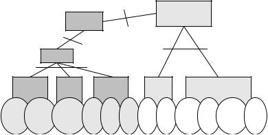
Figure 18.9 WCDMA/HSPA connected to LTE/SAE.
18.3.2.1 S1 flex and EPCs in pools
Similar to Iu flex, S1 flex enables a more robust core network. If one of the EPC nodes becomes unavailable another EPC node can take over the lost traffic. Furthermore, the scaling of the network is easier due to that EPC nodes can be added when needed due to traffic demands and not due to increase in coverage.
18.3.2.2 Roaming, policy control, and charging in SAE
Roaming is of course supported by the Evolved Packet Core. It is done between two EPC nodes: one in the visited network and one in the home network. Depending on operator policy the IP address can be allocated by the home or visited EPC.
18.3.3 WCDMA/HSPA connected to Evolved Packet Core
When LTE/SAE technology is being introduced in the network, handover to WCDMA/HSPA is needed. The way it is solved is to allow WCDMA/HSPA to connect to the Evolved Packet Core network. In fact, it is the SGSN of the GSM core network used for WCDMA/HSPA that is connected to the EPC. The EPC acts as a GGSN when the traffic is routed through the WCDMA/HSPA RAN using the S4 interface (which is based on the Gn/Gp interface used between GGSN and SGSN) and as a normal EPC when the traffic is routed through the LTE RAN. This is possible since the user plane termination in the EPC is kept and thus the IP address of the terminal. The control plane parts of the EPC are not used when the terminal is connected to the WCDMA/HSPA RAN. Instead the core network protocols of the SGSN are used. With this approach, minimal changes are needed to
System Architecture Evolution |
389 |
the packet core network used for WCDMA/HSPA while still being able to provide a fast and seamless handover to and from LTE (Figure 18.9).
When a handover from WCDMA/HSPA to LTE is needed, the connection is taken over by the EPC from the SGSN. This is done through the S3 interface which is based on the Gn interface used between SGSNs for SGSN relocations. Thus, the handover is close to the SGSN relocations with a user plane switch in the EPC instead of in the GGSN.
Performance of 3G evolution |
395 |
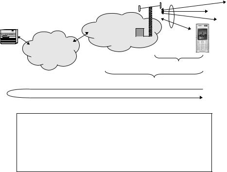
 System throughput
Radio
access NW
Server |
Core NW/ |
|
Internet |
Radio interface data rate
User throughput
Latency
•Radio interface data rate: Data rate of the physical layer achieved under certain radio conditions with specific coding and modulation.
•Peak data rate: Peak data rate of the radio interface under ideal radio conditions.
•User throughput: Data rate experienced above the MAC layer, under real channel conditions and after sharing the channel with other users.
•Latency: End-to-end round-trip time of a small packet.
•System throughput: Total number of bits per second transmitted over the radio interface (per sector).
Figure 19.1 Definitions of data rates for performance.
perceived speech or video quality. Superior-quality services have fewer bit errors in the received signal.
By contrast, users who download a web page or movie clip via packet data describe quality of service in terms of the delay they experience from the time they start the download until the web page or movie clip is displayed. Best-effort services do not guarantee a fixed data rate. Instead, users are allocated whatever data rate is available under present conditions. This is a general property of packet-switched networks, that is, network resources are not reserved for each user. Given that delay increases with the size of the object to be downloaded, absolute delay is not a fair measure of quality of service.
A lone user in a radio network experiencing good radio conditions may enjoy the peak data rate of the radio interface, see Figure 19.1. A user will, however, normally share radio resources with other users. If radio conditions are less than optimum or there is interference from other users, the radio interface data rate will be less than the peak data rate. In addition, some data packets might be lost, in which case the missing data must be retransmitted, further reducing the effective