3G Evolution. HSPA and LTE for Mobile Broadband
.pdfLTE physical layer |
323 |
f 15 kHz
One resource block


 (12 . 7 84 resource elements)
One |
|
|
|
|
slot (T |
|
|
|
|
slot |
|
|
|
|
0. |
|
|
|
|
|
5ms, |
7 |
OFDM |
|
|
|
|
||
|
|
|
symbols) |
|
|
|
|
|
|
Figure 16.6 Downlink resource block assuming normal cyclic prefix, i.e. seven OFDM symbols per slot. With extended cyclic prefix there are six OFDM symbols per slot and, consequently, a total of 72 resource elements in a resource block.
One |
slot |
|
|
|
|
|
|
|
(0. |
|
|
|
|
5ms) |
|
Frequency |
|
||
Time |
|
|
Downlink reference symbol |
Figure 16.7 LTE downlink reference-signal structure assuming normal cyclic prefix, i.e. seven OFDM symbols per slot.
16.2.2Downlink reference signals
To carry out downlink coherent demodulation, the mobile terminal needs estimates of the downlink channel. As described in Chapter 4, a straightforward way to enable channel estimation in case of OFDM transmission is to insert known reference symbols into the OFDM time-frequency grid. In LTE, these reference symbols are jointly referred to as the LTE downlink reference signals.
As illustrated in Figure 16.7, downlink reference symbols are inserted within the first and the third last4 OFDM symbols of each slot and with a frequency-domain spacing of six subcarriers. Furthermore, there is a frequency-domain staggering of three subcarriers between the first and second reference symbols. Within each resource block, consisting of 12 subcarriers during one slot, there are thus four reference symbols. This is true for all subframes except subframes used for MBSFN-based transmission (see further Section 16.2.6).
To estimate the channel over the entire time-frequency grid as well as reducing the noise in the channel estimates, the mobile terminal should carry out
4 This corresponds to the fifth and fourth OFDM symbols of the slot in case of normal and extended cyclic prefix, respectively.
324 |
3G Evolution: HSPA and LTE for Mobile Broadband |
interpolation/averaging over multiple reference symbols. Thus, when estimating the channel for a certain resource block, the mobile terminal may not only use the reference symbols within that resource block but also, in the frequency domain, neighbor resource blocks, as well as reference symbols of previously received slots/subframes. However, the extent to which the mobile terminal can average over multiple resource blocks in the frequency and/or time domain depends on the channel characteristics. In case of high channel frequency selectivity, the possibility for averaging in the frequency domain is limited. Similarly, the possibility for time-domain averaging, that is the possibility to use reference symbols in previously received slots/subframes, is limited in case of fast channel variations, for example, due to high mobile-terminal velocity. It should also be noted that, in case of TDD, the possibility for time averaging may be limited, as previous subframes may not even have been assigned for downlink transmission.
16.2.2.1 Reference-signals sequences and physical-layer cell identity
In general, the complex values of the reference symbols will vary between different reference-symbol positions and also between different cells. Thus, the reference signal of a cell can be seen as a two-dimensional sequence, in the LTE specifications referred to as a two-dimensional reference-signal sequence. Similar to the WCDMA/HSPA scrambling code, the LTE reference-signal sequence can be seen as an indicator of the LTE physical-layer cell identity. There are 510 referencesignal sequences defined in the LTE specification, corresponding to 510 different cell identities.
In terms of more details, each reference-signal sequence can be seen as the product of a two-dimensional pseudo-random sequence and a two-dimensional orthogonal sequence. There are a total of 170 different pseudo-random sequences defined by the LTE specification, each corresponding to one out of 170 cell-identity groups. Furthermore, there are three orthogonal sequences defined, each corresponding to a specific cell identity within each cell-identity group. The reference-signal sequences and their structure of being the product of a pseudo-random sequence and an orthogonal sequence can be used as part of the LTE cell search see further Chapter 17.
The reference-signal sequences should preferable be applied to cells in such a way that cells belonging to the same eNodeB are, as much as possible, assigned physical-layer cell identities within the same cell-identity group, i.e. assigned reference signals based on the same pseudo-random sequence but different orthogonal sequences. By doing so, the interference between reference signals of different cells of the same eNodeB can be minimized.
LTE physical layer |
325 |
16.2.2.2Reference-signal frequency hopping
In the reference-signal structure outlined in Figure 16.7, the frequency-domain positions of the reference symbols are the same between consecutive subframes. However, the frequency-domain positions of the reference symbols may also vary between consecutive subframes, also referred to as reference-symbol frequency hopping.
In case of reference-symbol frequency hopping, the relative positions of reference symbols within a subframe are the same as in Figure 16.7. Thus, the frequency hopping can be described as adding a sequence of frequency offsets, to the basic reference-symbol pattern outlined in Figure 16.7, with the offset being the same for all reference symbols within a subframe, but varying between consecutive subframes. The reference-symbol positions p in subframe k can thus be expressed as
First reference symbols: p(k) = (p0 + 6 · i + offset(k)) mod 6
Second reference symbols: p(k) = (p0 + 6 · i + 3 + offset(k)) mod 6
where i is an integer. The sequence of frequency offsets or the frequency-hopping pattern has a period of length 10, i.e. the frequency-hopping pattern is repeated between consecutive frames. There are 170 different frequency-hopping patterns defined, where each pattern corresponds to one cell-identity group.
By applying different frequency-hopping patterns to neighbor cells, the risk that reference symbols of neighbor cells are continuously colliding can be avoided. This is especially of interest if/when reference symbols are transmitted with higher energy compared to the remaining resource elements, also referred to as referencesignal energy boosting.
16.2.2.3Reference signals for multi-antenna transmission
In case of downlink multi-antenna transmission the mobile terminal must be able to estimate the downlink channel corresponding to each transmit antenna. To enable this, there is one downlink reference signal transmitted from each antenna. It should be pointed out that the LTE radio-access specification actually talks about antenna ports rather than antennas to emphasize that what is referred to does not necessarily correspond to a single physical antenna. Actually, an antenna port is defined by the presence of an antenna-port-specific reference signal. Thus, if identical reference signals are transmitted from several physical antennas, these antennas cannot be resolved from a mobile-terminal point-of-view and the
326 |
3G Evolution: HSPA and LTE for Mobile Broadband |
antennas can be jointly seen as a single antenna port. However, to simplify the text the term antenna will here be used.
•In case of two transmit antennas (Figure 16.8a) the reference symbols of the second antenna is frequency multiplexed with the reference symbols of the first antenna, with a frequency-domain offset of three subcarriers.
•In case of four transmit antennas (Figure 16.8b), reference symbols for the third and fourth antennas are frequency multiplexed within the second OFDM symbol of each slot. Note that the reference symbols for antenna three and four are only transmitted within one OFDM symbol of each slot.
It can also be noted that in a resource element carrying a reference symbol for a certain antenna nothing is being transmitted on the other antennas. Thus, the reference symbols of a certain antenna are not interfered by transmissions from other antennas within the cell.
Clearly, in the case of four transmit antennas the time-domain reference-symbol density of the third and fourth antennas is reduced compared to the first and second antenna. This is done in order to limit the reference-signal overhead in case of four transmit antennas. At the same time, this has a negative impact on the possibility to track very fast channel variations. However, this can be justified based on an expectation that, for example, four-antenna spatial multiplexing will mainly be applied to scenarios with low mobility. The reason for retaining the higher reference-symbol density for the first and second antennas also in case of four transmit antennas is that it is assumed that these reference signals will be used as part of the initial cell search during which the mobile terminal has not yet acquired full information about the number of transmit antennas within the cell. Thus, the configuration of the reference signals of the first and second antenna should be the same regardless of the number of antennas.
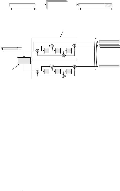
16.2.3Downlink transport-channel processing
As discussed in Chapter 15, the physical layer interfaces to higher layers, more specifically to the MAC layer, by means of Transport Channels. LTE has inherited the basic principle of WCDMA/HSPA that data is delivered to the physical layer in the form of Transport Blocks of a certain size. In terms of the more detailed transport-block structure, LTE has adopted a similar approach as was adopted for HSPA:
•In case of single-antenna transmission there can be at most one single transport block of dynamic size for each TTI.
•In case of multi-antenna transmission there can be up to two transport blocks of dynamic size for each TTI, where each transport block corresponds to one
328 |
3G Evolution: HSPA and LTE for Mobile Broadband |
Transport block(s) of dynamic size delivered from MAC layer
|
|
|
|
|
|
|
|
|
|
|
|
|
|
|
|
|
|
|
CRC insertion |
|
|
|
|
|
|
|
|
|
|
|
|
|
|
|
|
|
|
|
|
|
|
|
|
|
|
|
|
|
|
|
|
|
|
|
||
|
|
CRC |
|
|
|
CRC |
|
|
||||||||||
|
|
|
|
|
|
|
|
|
|
|
|
|||||||
|
|
|
|
|
|
|
|
|
|
|
||||||||
Channel coding |
|
|
|
|
|
|
|
|
|
|
|
|
|
|
|
|
|
|
|
|
Coding |
|
|
|
Coding |
|
|
||||||||||
Physical-layer hybrid-ARQ |
|
|
|
|
|
|
|
|
|
|
|
|
|
|
|
|
|
|
|
|
|
|
|
|
|
|
|
|
|
|
|
|
|
|
|
||
|
|
|
|
|
|
|
|
|
|
|
|
|
|
|
|
|
||
|
|
HARQ |
|
|
|
HARQ |
|
|
||||||||||
functionality |
|
|
|
|
|
|
|
|||||||||||
|
|
|
|
|
|
|
|
|
|
|
|
|
|
|
|
|
||
|
|
|
|
|
|
|
|
|
|
|||||||||
Bit-level scrambling |
|
|
|
|
|
|
|
|
|
|
|
|
|
|
|
|
|
|
|
Scrambling |
|
|
|
Scrambling |
|
|
|||||||||||
|
|
|
|
|
|
|
|
|
|
|
||||||||
|
|
|
|
|
|
|
|
|
||||||||||
Data modulation |
|
|
|
|
|
|
|
|
|
|
|
|
|
|
|
|
|
|
|
Modulation |
|
|
|
Modulation |
|
|
|||||||||||
|
|
|
|
|
|
|
|
|
|
|
|
|
|
|
|
|
|
|
Antenna mapping |
|
|
|
|
|
|
|
|
|
|
|
|
|
|
|
|
||
|
|
|
|
|
|
|
|
|
|
|
|
|
|
|
|
|||
|
|
|
|
|
Antenna mapping |
|
|
|
||||||||||
|
|
|
|
|
|
|
|
|
|
|
|
|
|
|
|
Up to four antennas |
||
|
|
|
|
|
|
|
|
|
|
|
|
|
|
|
|
|||
Resource-block mapping |
|
|
|
|
|
|
|
|
|
|
|
|
|
|
|
|
||
|
RM |
|
|
|
|
|
RM |
|
|
|
||||||||
|
|
|
|
|
|
|
|
|
|
|
|
|
|
|
|
|
|
|
To OFDM modulation for each antenna
Figure 16.9 LTE downlink transport-channel processing. Dashed parts are only present in case of downlink spatial multiplexing, that is when two transport blocks are transmitted in parallel within a TTI.
codeword in case of downlink spatial multiplexing. This implies that, although LTE supports downlink spatial multiplexing with up to four transmit antennas, the number of codewords is still limited to two. More details on LTE downlink multi-antenna transmission are provided in Section 16.2.5.
With this transport-block structure in mind, the LTE downlink transport-channel processing, more specifically the processing of DL-SCH,5 can be outlined according to Figure 16.9 with two, mainly separated, processing chains, each corresponding to the processing of a single transport block. The second processing chain, corresponding to a second transport block, is thus only present in the case of downlink spatial multiplexing. In this case, the two transport blocks of, in general, different sizes are combined as part of the Antenna Mapping in the lower part of Figure 16.9.
5 The processing of other downlink transport channels is similar although, typically, with some additional constraints.

LTE physical layer |
331 |
Scrambling sequence (M bits)
|
|
|
|
|
|
|
M bits |
|
|
|
|
|
M bits |
Figure 16.13 Downlink scrambling.
that the receiver-side decoding can fully utilize the processing gain provided by the channel code. Without downlink scrambling, the channel decoder at the mobile terminal could, at least in principle, be equally matched to an interfering signal as to the target signal, thus not being able to properly suppress the interference. By applying different scrambling sequences for neighbor cells, the interfering signal(s) after de-scrambling are randomized, ensuring full utilization of the processing gain provided by the channel code.
In contrast to HSPA, where downlink scrambling is applied to the complex chips after spreading (chip-level scrambling), LTE applies downlink scrambling to the code bits of each transport channel (bit-level scrambling). Chip-level scrambling is necessary for HSPA to ensure that the processing gain provided by the spreading can be efficiently utilized. On the other hand, scrambling of code bits rather than complex modulation symbols implies somewhat lower implementation complexity, with no negative impact on performance in case of LTE.
In LTE, downlink scrambling is applied to all transport channels. Scrambling is also applied to the downlink L1/L2 control signaling (see Section 16.2.4). For all downlink transport channels except the MCH, as well as for the L1/L2 control signaling, the scrambling sequences should be different for neighbor cells (cellspecific scrambling) to ensure interference randomization between the cells. In contrast, in case of MBSFN-based transmission using the MCH transport channel, the same scrambling should be applied to all cells taking part in a certain MBSFN transmission (cell-common scrambling) (see further Section 16.2.6).
16.2.3.5Data modulation
The downlink data modulation transforms a block of scrambled bits to a corresponding block of complex modulation symbols (Figure 16.14). The set of modulation schemes supported for the LTE downlink includes QPSK, 16QAM, and 64QAM, corresponding to two, four, and six bits per modulation symbol, respectively. All these modulation schemes are applicable in case of DL-SCH transmission. For other transport channels certain restrictions may apply. As an example, only QPSK modulation can be applied in case of BCH transmission.