

Rotorcraft Flying Handbook
.pdfCh 06.qxd 7/15/2003 9:11 AM Page 6-2
operating limitations, instrument markings, color coding, and basic placards. Some of the areas included are: airspeed, altitude, rotor, and powerplant limitations, including fuel and oil requirements; weight and loading distribution; and flight limitations.
Figure 6-2. Typical airspeed indicator limitations and markings.
AIRSPEED LIMITATIONS
Airspeed limitations are shown on the airspeed indicator by color coding and on placards or graphs in the aircraft. A red line on the airspeed indicator shows the airspeed limit beyond which structural damage could occur. This is called the never exceed speed, or VNE. The normal operating speed range is depicted by a green arc. A blue line is sometimes added to show the maximum safe autorotation speed. [Figure 6-2]
Figure 6-3. Markings on a typical dual-needle tachometer in a reciprocating-engine helicopter. The outer band shows the limits of the superimposed needles when the engine is turning the rotor.
The inner band indicates the power-off limits.
ALTITUDE LIMITATIONS
If the rotorcraft has a maximum operating density altitude, it is indicated in this section of the flight manual. Sometimes the maximum altitude varies based on different gross weights.
ROTOR LIMITATIONS
Low rotor r.p.m. does not produce sufficient lift, and high r.p.m. may cause structural damage, therefore rotor r.p.m. limitations have minimum and maximum values. A green arc depicts the normal operating range with red lines showing the minimum and maximum limits. [Figure 6-3]
There are two different rotor r.p.m. limitations: power-on and power-off. Power-on limitations apply anytime the engine is turning the rotor and is depicted by a fairly narrow green band. A yellow arc may be included to show a transition range, which means that operation within this range is limited. Power-off limitations apply anytime the engine is not turning the rotor, such as when in an autorotation. In this case, the green arc is wider than the power-on arc, indicating a larger operating range.
Figure 6-4. Torque and turbine outlet temperature (TOT) gauges are commonly used with turbine-powered aircraft.
POWERPLANT LIMITATIONS
The Powerplant Limitations area describes operating limitations on the rotorcraft’s engine including such items as r.p.m. range, power limitations, operating temperatures, and fuel and oil requirements. Most turbine engines and some reciprocating engines have a maximum power and a maximum continuous power rating. The “maximum power” rating is the maximum power the engine can generate and is usually limited by time. The maximum power range is depicted by a yellow arc on the engine power instruments, with a red line indicating the maximum power that must not be exceeded. “Maximum continuous power” is the maximum power the engine can generate con-

Ch 06.qxd 7/15/2003 9:11 AM Page 6-3
Figure 6-5. A manifold pressure gauge is commonly used with pis- ton-powered aircraft.
tinually, and is depicted by a green arc. [Figure 6- 4]
Like on a torque and turbine outlet temperature gauge, the red line on a manifold pressure gauge indicates the maximum amount of power. A yellow arc on the gauge warns of pressures approaching the limit of rated power. A placard near the gauge lists the maximum readings for specific conditions. [Figure 6-5]
WEIGHT AND LOADING DISTRIBUTION
The Weight and Loading Distribution area contains the maximum certificated weights, as well as the center of gravity (CG) range. The location of the reference datum used in balance computations should also be included in this section. Weight and balance computations are not provided here, but rather in the Weight and Balance Section of the FAAApproved Rotocraft Flight Manual.
FLIGHT LIMITATIONS
This area lists any maneuvers which are prohibited, such as acrobatic flight or flight into known icing conditions. If the rotorcraft can only be flown in VFR conditions, it will be noted in this area. Also included are the minimum crew requirements, and the pilot seat location, if applicable, where solo flights must be conducted.
PLACARDS
All rotorcraft generally have one or more placards displayed that have a direct and important bearing on the safe operation of the rotorcraft. These placards are located in a conspicuous place within the cabin and normally appear in the Limitations Section. Since VNE changes with altitude, this placard can be found in all helicopters. [Figure 6- 6]
Figure 6-6. Various VNE placards.
EMERGENCY PROCEDURES
Concise checklists describing the recommended procedures and airspeeds for coping with various types of emergencies or critical situations can be found in this section. Some of the emergencies covered include: engine failure in a hover and at altitude, tail rotor failures, fires, and systems failures. The procedures for restarting an engine and for ditching in the water might also be included.
Manufacturers may first show the emergencies checklists in an abbreviated form with the order of items reflecting the sequence of action. This is followed by amplified checklists providing additional information to help you understand the procedure. To be prepared for an abnormal or emergency situation, memorize the first steps of each checklist, if not all the steps. If time permits, you can then refer to the checklist to make sure all items have been covered. (For more information on emergencies, refer to Chapter 11—Helicopter Emergencies and Chapter 21—Gyroplane Emergencies.)
Manufacturers also are encouraged to include an optional area titled “Abnormal Procedures,” which describes recommended procedures for handling malfunctions that are not considered to be emergencies. This information would most likely be found in larger helicopters.
Ch 06.qxd 7/15/2003 9:11 AM Page 6-4
NORMAL PROCEDURES
The Normal Procedures is the section you will probably use the most. It usually begins with a listing of the airspeeds, which may enhance the safety of normal operations. It is a good idea to memorize the airspeeds that are used for normal flight operations. The next part of the section includes several checklists, which take you through the preflight inspection, before starting
Figure 6-7. One of the performance charts in the Performance Section is the “In Ground Effect Hover Ceiling versus Gross Weight” chart. This chart allows you to determine how much weight you can carry and still operate at a specific pressure altitude, or if you are carrying a specific weight, what is your altitude limitation.
procedure, how to start the engine, rotor engagement, ground checks, takeoff, approach, landing, and shutdown. Some manufacturers also include the procedures for practice autorotations. To avoid skipping an important step, you should always use a checklist when one is available. (More information on maneuvers can be found in Chapter 9— Basic Maneuvers, Chapter 10—Advanced Maneuvers, and Chapter 20—Gyroplane Flight Operations.)
PERFORMANCE
The Performance Section contains all the information required by the regulations, and any additional performance information the manufacturer feels may enhance your ability to safely operate the rotorcraft. These charts, graphs, and tables vary in style but all contain the same basic information. Some examples of the performance information that can be found in most flight manuals include a calibrated versus indicated airspeed conversion graph, hovering ceiling versus gross weight charts, and a height-velocity diagram. [Figure 6-7] For information on how to use the charts, graphs, and tables, refer to Chapter 8—Performance.
WEIGHT AND BALANCE
The Weight and Balance section should contain all the information required by the FAA that is necessary to calculate weight and balance. To help you correctly compute the proper data, most manufacturers include sample problems. (Weight and balance is further discussed in Chapter 7—Weight and Balance.)
AIRCRAFT AND SYSTEMS DESCRIPTION
The Aircraft and Systems Description section is an excellent place to study and familiarize yourself with all the systems found on your aircraft. The manufacturers should describe the systems in a manner that is understandable to most pilots. For larger, more complex rotorcraft, the manufacturer may assume a higher degree of knowledge. (For more information on rotorcraft systems, refer to Chapter 5—Helicopter Systems and Chapter 18—Gyroplane Systems.)
HANDLING, SERVICING, AND MAINTENANCE
The Handling, Servicing, and Maintenance section describes the maintenance and inspections recommended by the manufacturer, as well as those required by the regulations, and Airworthiness Directive (AD) compliance procedures. There are also suggestions on how the
Airworthiness Directive (AD)—A regulatory notice that is sent out by the FAA to the registered owners of aircraft informing them of the discovery of a condition that keeps their aircraft from continuing to meet its conditions for airworthiness. Airworthiness Directives must be complied with within the required time limit, and the fact of compliance, the date of compliance, and the method of compliance must be recorded in the aircraft maintenance records.

Ch 07.qxd 7/15/2003 9:11 AM Page 7-1
It is vital to comply with weight and balance limits established for helicopters. Operating above the maximum weight limitation compromises the structural integrity of the helicopter and adversely affects performance. Balance is also critical because on some fully loaded helicopters, center of gravity deviations as small as three inches can dramatically change a helicopter’s handling characteristics. Taking off in a helicopter that is not within the weight and balance limitations is unsafe.
WEIGHT
When determining if your helicopter is within the weight limits, you must consider the weight of the basic helicopter, crew, passengers, cargo, and fuel. Although the effective weight (load factor) varies during maneuvering flight, this chapter primarily considers the weight of the loaded helicopter while at rest.
The following terms are used when computing a helicopter’s weight.
BASIC EMPTY WEIGHT—The starting point for weight computations is the basic empty weight, which is the weight of the standard helicopter, optional equipment, unusable fuel, and full operating fluids including full engine oil. Some helicopters might use the term “licensed empty weight,” which is nearly the same as basic empty weight, except that it does not include full engine oil, just undrainable oil. If you fly a helicopter that lists a licensed empty weight, be sure to add the weight of the oil to your computations.
USEFUL LOAD—The difference between the gross weight and the basic empty weight is referred to as useful load. It includes the flight crew, usable fuel, drainable oil, if applicable, and payload.
PAYLOAD—The weight of the passengers, cargo, and baggage.
GROSS WEIGHT—The sum of the basic empty weight and useful load.
MAXIMUM GROSS WEIGHT— The maximum weight of the helicopter. Most helicopters have an
internal maximum gross weight, which refers to the weight within the helicopter structure and an external maximum gross weight, which refers to the weight of the helicopter with an external load.
WEIGHT LIMITATIONS
Weight limitations are necessary to guarantee the structural integrity of the helicopter, as well as enabling you to predict helicopter performance accurately. Although aircraft manufacturers build in safety factors, you should never intentionally exceed the load limits for which a helicopter is certificated. Operating above a maximum weight could result in structural deformation or failure during flight if you encounter excessive load factors, strong wind gusts, or turbulence. Operating below a minimum weight could adversely affect the handling characteristics of the helicopter. During single-pilot operations in some helicopters, you may have to use a large amount of forward cyclic in order to maintain a hover. By adding ballast to the helicopter, the cyclic will be closer to the center, which gives you a greater range of control motion in every direction. Additional weight also improves autorotational characteristics since the autorotational descent can be established sooner. In addition, operating below minimum weight could prevent you from achieving the desirable rotor r.p.m. during autorotations.
Although a helicopter is certificated for a specified maximum gross weight, it is not safe to take off with this load under all conditions. Anything that adversely affects takeoff, climb, hovering, and landing performance may require off-loading of fuel, passengers, or baggage to some weight less than the published maximum. Factors which can affect performance include high altitude, high temperature, and high humidity conditions, which result in a high density altitude.
DETERMINING EMPTY WEIGHT
A helicopter’s weight and balance records contain essential data, including a complete list of all installed optional equipment. Use these records to determine the weight and balance condition of the empty helicopter.

Ch 07.qxd 7/15/2003 9:11 AM Page 7-2
When a helicopter is delivered from the factory, the basic empty weight, empty weight center of gravity (CG), and useful load are recorded on a weight and balance data sheet included in the FAA-Approved Rotocraft Flight Manual. The basic empty weight can vary even in the same model of helicopter because of differences in installed equipment. If the owner or operator of a helicopter has equipment removed, replaced, or additional equipment installed, these changes must be reflected in the weight and balance records. In addition, major repairs or alterations must be recorded by a certified mechanic. When the revised weight and moment are recorded on a new form, the old record is marked with the word “superseded” and dated with the effective date of the new record. This makes it easy to determine which weight and balance form is the latest version. You must use the latest weight and balance data for computing all loading problems.
BALANCE
Helicopter performance is not only affected by gross weight, but also by the position of that weight. It is essential to load the aircraft within the allowable center-of-gravity range specified in the rotorcraft flight manual’s weight and balance limitations.
CENTER OF GRAVITY (CG)
The center of gravity is defined as the theoretical point where all of the aircraft’s weight is considered to be concentrated. If a helicopter was suspended by a cable attached to the center-of-gravity point, it would balance like a teeter-totter. For helicopters with a single main rotor, the CG is usually close to the main rotor mast.
Improper balance of a helicopter’s load can result in serious control problems. The allowable range in which the CG may fall is called the “CG range.” The exact CG location and range are specified in the rotorcraft flight manual for each helicopter. In addition to making a helicopter difficult to control, an out-of-balance loading condition also decreases maneuverability since cyclic control is
less effective in the direction opposite to the CG location.
Ideally, you should try to perfectly balance a helicopter so that the fuselage remains horizontal in hovering flight, with no cyclic pitch control needed except for wind correction. Since the fuselage acts as a pendulum suspended from the rotor, changing the center of gravity changes the angle at which the aircraft hangs from the rotor. When the center of gravity is directly under the rotor mast, the helicopter hangs horizontal; if the CG is too far forward of the mast, the helicopter hangs with its nose tilted down; if the CG is too far aft of the mast, the nose tilts up. [Figure 7-1]
CG FORWARD OF FORWARD LIMIT
A forward CG may occur when a heavy pilot and passenger take off without baggage or proper ballast located aft of the rotor mast. This situation becomes worse if the fuel tanks are located aft of the rotor mast because as fuel burns the weight located aft of the rotor mast becomes less.
You can recognize this condition when coming to a hover following a vertical takeoff. The helicopter will have a nose-low attitude, and you will need excessive rearward displacement of the cyclic control to maintain a hover in a no-wind condition. You should not continue flight in this condition, since you could rapidly run out of rearward cyclic control as you consume fuel. You also may find it impossible to decelerate sufficiently to bring the helicopter to a stop. In the event of engine failure and the resulting autorotation, you may not have enough cyclic control to flare properly for the landing.
A forward CG will not be as obvious when hovering into a strong wind, since less rearward cyclic displacement is required than when hovering with no wind. When determining whether a critical balance condition exists, it is essential to consider the wind velocity and its relation to the rearward displacement of the cyclic control.
Figure 7-1. The location of the center of gravity strongly influences how the helicopter handles.
Ch 07.qxd 7/15/2003 9:11 AM Page 7-3
CG AFT OF AFT LIMIT
Without proper ballast in the cockpit, exceeding the aft CG may occur when:
•A lightweight pilot takes off solo with a full load of fuel located aft of the rotor mast.
•A lightweight pilot takes off with maximum baggage allowed in a baggage compartment located aft of the rotor mast.
•A lightweight pilot takes off with a combination of baggage and substantial fuel where both are aft of the rotor mast.
You can recognize the aft CG condition when coming to a hover following a vertical takeoff. The helicopter will have a tail-low attitude, and you will need excessive forward displacement of cyclic control to maintain a hover in a no-wind condition. If there is a wind, you need even greater forward cyclic.
If flight is continued in this condition, you may find it impossible to fly in the upper allowable airspeed range due to inadequate forward cyclic authority to maintain a nose-low attitude. In addition, with an extreme aft CG, gusty or rough air could accelerate the helicopter to a speed faster than that produced with full forward cyclic control. In this case, dissymmetry of lift and blade flapping could cause the rotor disc to tilt aft. With full forward cyclic control already applied, you might not be able to lower the rotor disc, resulting in possible loss of control, or the rotor blades striking the tailboom.
LATERAL BALANCE
For most helicopters, it is usually not necessary to determine the lateral CG for normal flight instruction and passenger flights. This is because helicopter cabins are relatively narrow and most optional equipment is located near the center line. However, some helicopter manuals specify the seat from which you must conduct solo flight. In addition, if there is an unusual situation, such as a heavy pilot and a full load of fuel on one side of the helicopter, which could affect the lateral CG, its position should be checked against the CG envelope. If carrying external loads in a position that requires large lateral cyclic control displacement to maintain level flight, fore and aft cyclic effectiveness could be dramatically limited.
WEIGHT AND BALANCE CALCULATIONS
When determining whether your helicopter is properly loaded, you must answer two questions:
1.Is the gross weight less than or equal to the maximum allowable gross weight?
2.Is the center of gravity within the allowable CG range, and will it stay within the allowable range as fuel is burned off?
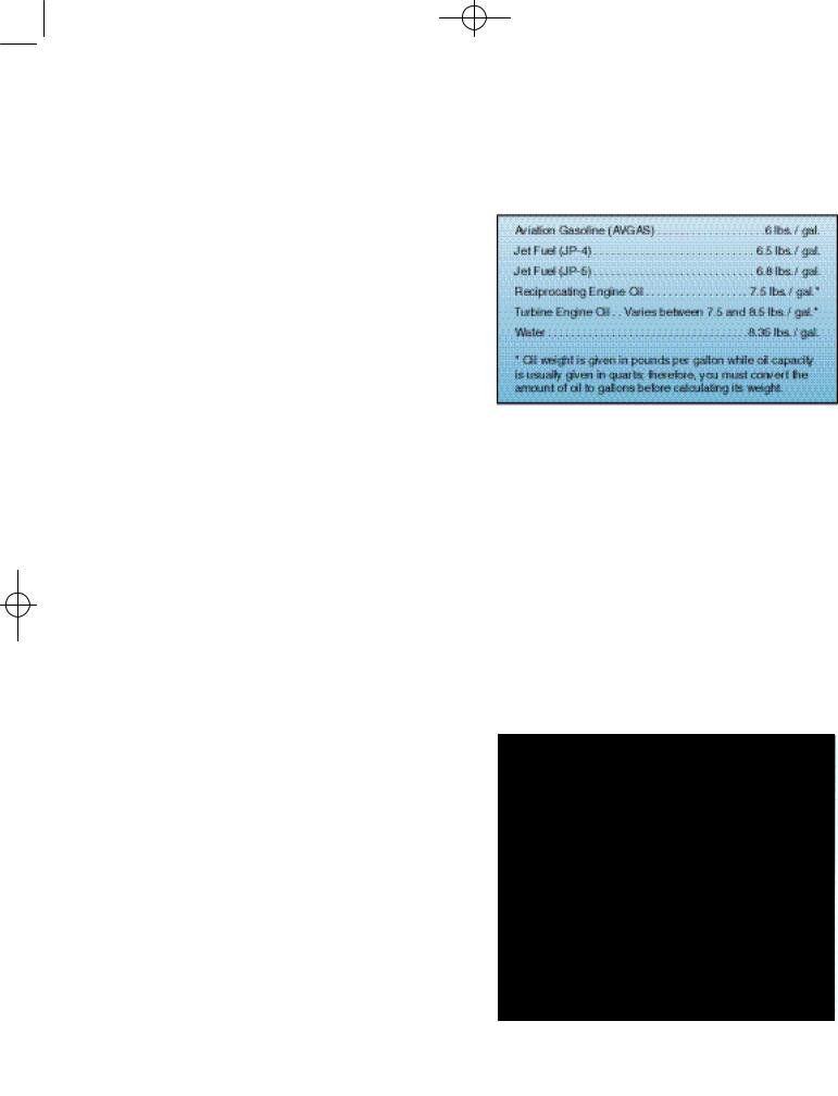
Figure 7-2. When making weight and balance computations, always use actual weights if they are available, especially if the helicopter is loaded near the weight and balance limits.
To answer the first question, just add the weight of the items comprising the useful load (pilot, passengers, fuel, oil, if applicable, cargo, and baggage) to the basic empty weight of the helicopter. Check that the total weight does not exceed the maximum allowable gross weight.
To answer the second question, you need to use CG or moment information from loading charts, tables, or graphs in the rotorcraft flight manual. Then using one of the methods described below, calculate the loaded moment and/or loaded CG and verify that it falls within the allowable CG range shown in the rotorcraft flight manual.
Figure 7-3. While the horizontal reference datum can be anywhere the manufacturer chooses, most small training helicopters have the horizontal reference datum 100 inches forward of the main rotor shaft centerline. This is to keep all the computed values positive.

Ch 07.qxd 7/15/2003 9:11 AM Page 7-4
It is important to note that any weight and balance computation is only as accurate as the information provided. Therefore, you should ask passengers what they weigh and add a few pounds to cover the additional weight of clothing, especially during the
Figure 7-4. The lateral reference datum is located longitudinally through the center of the helicopter; therefore, there are positive and negative values.
ter, or even at a point in space ahead of the helicopter. [Figure 7-3]
The lateral reference datum, is usually located at the center of the helicopter. The location of the reference datums is established by the manufacturer and is defined in the rotorcraft flight manual. [Figure 7-4]
ARM—The horizontal distance from the datum to any component of the helicopter or to any object located within the helicopter is called the arm. Another term that can be used interchangeably with arm is station. If the component or object is located to the rear of the datum, it is measured as a positive number and usually is referred to as inches aft of the datum. Conversely, if the component or object is located forward of the datum, it is indicated as a negative number and is usually referred to as inches forward of the datum.
winter months. The baggage weight should be determined by the use of a scale, if practical. If a scale is not available, be conservative and overestimate the weight. Figure 7-2 indicates the standard weights for specific operating fluids.
The following terms are used when computing a helicopter’s balance.
REFERENCE DATUM—Balance is determined by the location of the CG, which is usually described as a given number of inches from the reference datum. The horizontal reference datum is an imaginary vertical plane or point, arbitrarily fixed somewhere along the longitudinal axis of the helicopter, from which all horizontal distances are measured for weight and balance purposes. There is no fixed rule for its location. It may be located at the rotor mast, the nose of the helicop-
Figure 7-5. In this example, the helicopter’s weight of 1,700 pounds is recorded in the first column, its CG or arm of 116.5 inches in the second, and its moment of 198,050 pound-inches in the last. Notice that the weight of the helicopter, multiplied by its CG, equals its moment.
MOMENT—If the weight of an object is multiplied by its arm, the result is known as its moment. You may think of moment as a force that results from an object’s weight acting at a distance. Moment is also referred to as the tendency of an object to rotate or pivot about a point. The farther an object is from a pivotal point, the greater its force.
CENTER OF GRAVITY COMPUTATION—By totaling the weights and moments of all components and objects carried, you can determine the point where a loaded helicopter would balance. This point is known as the center of gravity.

Ch 07.qxd 7/15/2003 9:11 AM Page 7-5
WEIGHT AND BALANCE METHODS
Since weight and balance is so critical to the safe operation of a helicopter, it is important to know how to check this condition for each loading arrangement. Most helicopter manufacturers use one of two methods, or a combination of the methods, to check weight and balance conditions.
COMPUTATIONAL METHOD
With the computational method, you use simple mathematics to solve weight and balance problems. The first step is to look up the basic empty weight and total moment for the particular helicopter you fly. If the center of gravity is given, it should also be noted. The empty weight CG can be considered the arm of the empty helicopter. This should be the first item recorded on the weight and balance form. [Figure 7-5]
Next, the weights of the oil, if required, pilot, passengers, baggage, and fuel are recorded. Use care in recording the weight of each passenger and baggage. Recording each weight in its proper location is extremely important to the accurate calculation of a CG. Once you have recorded all of the weights, add them together to determine the total weight of the loaded helicopter.
Now, check to see that the total weight does not exceed the maximum allowable weight under existing conditions. In this case, the total weight of the helicopter is under the maximum gross weight of 3,200 pounds.
Figure 7-6. Loading chart illustrating the solution to sample problems 1 and 2.
Once you are satisfied that the total weight is within prescribed limits, multiply each individual weight by its associated arm to determine its
moment. Then, add the moments together to arrive at the total moment for the helicopter. Your final computation is to find the center of gravity of the loaded helicopter by dividing the total moment by the total weight.
After determining the helicopter’s weight and center of gravity location, you need to determine if the CG is within acceptable limits. In this example, the allowable range is between 106.0 inches and 114.2 inches. Therefore, the CG location is within the acceptable range. If the CG falls outside the acceptable limits, you will have to adjust the loading of the helicopter.
LOADING CHART METHOD
You can determine if a helicopter is within weight and CG limits using a loading chart similar to the one in figure 7-6. To use this chart, first subtotal the empty weight, pilot, and passengers. This is the weight at which you enter the chart on the left. The next step is to follow the upsloping lines for baggage and then for fuel to arrive at your final weight and CG. Any value on or inside the envelope is within the range.
SAMPLE PROBLEM 1
Determine if the gross weight and center of gravity are within allowable limits under the following loading conditions for a helicopter based on the loading chart in figure 7-6.
To use the loading chart for the helicopter in this example, you must add up the items in a certain order. The maximum allowable gross weight is 1,600 pounds.
ITEM |
POUNDS |
Basic empty weight |
1,040 |
Pilot |
135 |
Passenger |
200 |
Subtotal |
1,375 (point A) |
Baggage compartment load |
25 |
Subtotal |
1,400 (point |
B) |
|
Fuel load (30 gallons) |
180 |
Total weight |
1,580 (point |
C) |
|
1.Follow the green arrows in figure 7-6. Enter the graph on the left side at 1,375 lb., the subtotal of the empty weight and the passenger weight. Move right to the yellow line. (point A)

Ch 07.qxd 7/15/2003 9:11 AM Page 7-6
2.Move up and to the right, parallel to the bagweight, point F falls outside the aft allowable CG
gage compartment loading lines to 1,400 lb. |
limit. |
(Point B) |
As you can see, it is important to reevaluate the bal- |
|
3.Continue up and to the right, this time paralance in a helicopter whenever you change the load-
lel to the fuel loading lines, to the total weight of 1,580 lb. (Point C).
Point C is within allowable weight and CG limits.
SAMPLE PROBLEM 2
Assume that the pilot in sample problem 1 discharges the passenger after using only 20 pounds of fuel.
ITEM |
POUNDS |
Basic empty weight |
1,040 |
Pilot |
135 |
Subtotal |
1,175 (point |
D) |
|
Baggage compartment load |
25 |
Subtotal |
1,200 (point |
E) |
|
Fuel load |
160 |
ing. Unlike most airplanes, where discharging a passenger is unlikely to adversely affect the CG, off-loading a passenger from a helicopter could make the aircraft unsafe to fly. Another difference between helicopter and airplane loading is that most small airplanes carry fuel in the wings very
Figure 7-7. Moments for fuel, pilot, and passenger.
Total weight |
1,360 (point F) |
Follow the blue arrows in figure 7-6, starting at 1,175 lb. on the left side of the graph, then to point D, E, and F. Although the total weight of the helicopter is well below the maximum allowable gross
Figure 7-8. CG/Moment Chart.
near the center of gravity. Burning off fuel has little effect on the loaded CG. However, helicopter fuel tanks are often significantly behind the center of gravity. Consuming fuel from a tank aft of the rotor mast causes the loaded helicopter CG to move forward. As standard practice, you should compute the weight and balance with zero fuel to verify that your helicopter remains within the acceptable limits as fuel is used.
SAMPLE PROBLEM 3
The loading chart used in the sample problems 1 and 2 is designed to graphically calculate the loaded center of gravity and show whether it is within limits, all on a single chart. Another type of loading chart calculates moments for each station.

Ch 07.qxd 7/15/2003 9:11 AM Page 7-7
Figure 7-9. Use the longitudinal CG envelope along with the computed CGs to determine if the helicopter is loaded properly.
You must then add up these moments and consult another graph to determine whether the total is within limits. Although this method has more steps, the charts are sometimes easier to use.
To begin, record the basic empty weight of the helicopter, along with its total moment. Remember to use the actual weight and moment of the helicopter you are flying. Next, record the weights of the pilot, passengers, fuel, and baggage on a weight and balance worksheet. Then, determine the total weight of the helicopter. Once you have determined the weight to be within prescribed limits, compute the moment for each weight and for the loaded helicopter. Do this with a loading graph provided by the manufacturer. Use figure 7-7 to determine the moments for a pilot and passenger weighing 340 pounds and for 211 pounds of fuel.
Start at the bottom scale labeled LOAD WEIGHT. Draw a line from 211 pounds up to the line labeled “FUEL @ STA108.5.” Draw your line to the left to intersect the MOMENT scale and read the fuel moment (22.9 thousand lb.-inches). Do the same for the pilot/passenger moment. Draw a line from a weight of 340 pounds up to the line labeled “PILOT & PASSENGER @STA. 83.2.” Go left and read the
Figure 7-10. Computed Lateral CG.