

Rotorcraft Flying Handbook
.pdfCh 03.qxd 7/15/2003 9:08 AM Page 3-10
TURNING FLIGHT
In forward flight, the rotor disc is tilted forward, which also tilts the total lift-thrust force of the rotor disc forward. When the helicopter is banked, the rotor disc is tilted sideward resulting in lift being separated into two components. Lift acting upward and opposing weight is called the vertical compo-
nent of lift. Lift acting horizontally and opposing inertia (centrifugal force) is the horizontal component of lift (centripetal force). [Figure 3-19]
As the angle of bank increases, the total lift force is tilted more toward the horizontal, thus causing the rate of turn to increase because more lift is acting
Figure 3-22. Force vectors in vertical autorotation descent.
Ch 03.qxd 7/15/2003 9:08 AM Page 3-11
horizontally. Since the resultant lifting force acts more horizontally, the effect of lift acting vertically is deceased. To compensate for this decreased vertical lift, the angle of attack of the rotor blades must be increased in order to maintain altitude. The steeper the angle of bank, the greater the angle of attack of the rotor blades required to maintain altitude. Thus, with an increase in bank and a greater angle of attack, the resultant lifting force increases and the rate of turn is faster.
AUTOROTATION
Autorotation is the state of flight where the main rotor system is being turned by the action of relative wind rather than engine power. It is the means by which a helicopter can be landed safely in the event of an engine failure. In this case, you are using altitude as potential energy and converting it to kinetic energy during the descent and touchdown. All helicopters must have this capability in order to be certified. Autorotation is permitted mechanically because of a freewheeling unit, which allows the main rotor to continue turning even if the engine is not running. In normal powered flight, air is drawn into the main rotor system from above and exhausted downward. During autorotation, airflow enters the rotor disc from below as the helicopter descends. [Figure 3-20]
AUTOROTATION (VERTICAL FLIGHT)
Most autorotations are performed with forward speed. For simplicity, the following aerodynamic explanation is based on a vertical autorotative descent (no forward speed) in still air. Under these conditions, the forces that cause the blades to turn are similar for all blades regardless of their position in the plane of rotation. Therefore, dissymmetry of lift resulting from helicopter airspeed is not a factor.
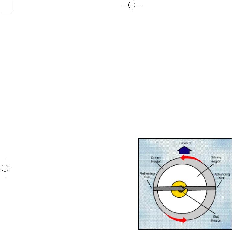
During vertical autorotation, the rotor disc is divided into three regions as illustrated in figure 3- 21—the driven region, the driving region, and the stall region. Figure 3-22 shows four blade sections
that illustrate force vectors. Part A is the driven region, B and D are points of equilibrium, part C is the driving region, and part E is the stall region. Force vectors are different in each region because rotational relative wind is slower near the blade root and increases continually toward the blade tip. Also, blade twist gives a more positive angle of attack in the driving region than in the driven region. The combination of the inflow up through the rotor with rotational relative wind produces different combinations of aerodynamic force at every point along the blade.
The driven region, also called the propeller region, is nearest the blade tips. Normally, it consists of about 30 percent of the radius. In the driven region, part A of figure 3-22, the total aerodynamic force acts behind the axis of rotation, resulting in a overall drag force. The driven region produces some lift, but that lift is offset by drag. The overall result is a deceleration in the rotation of the blade. The size of this region varies with the blade pitch, rate of descent, and rotor r.p.m. When changing
Figure 3-23. Blade regions in forward autorotation descent.
autorotative r.p.m., blade pitch, or rate of descent, the size of the driven region in relation to the other regions also changes.
There are two points of equilibrium on the blade— one between the driven region and the driving region, and one between the driving region and the stall region. At points of equilibrium, total aerodynamic force is aligned with the axis of rotation. Lift and drag are produced, but the total effect produces neither acceleration nor deceleration.

Ch 03.qxd 7/15/2003 9:08 AM Page 3-12
The driving region, or autorotative region, normally lies between 25 to 70 percent of the blade radius. Part C of figure 3-22 shows the driving region of the blade, which produces the forces needed to turn the blades during autorotation. Total aerodynamic force in the driving region is inclined slightly forward of the axis of rotation, producing a continual acceleration force. This inclination supplies thrust, which tends to accelerate the rotation of the blade. Driving region size varies with blade pitch setting, rate of descent, and rotor r.p.m.
By controlling the size of this region you can adjust autorotative r.p.m. For example, if the collective pitch is raised, the pitch angle increases in all regions. This causes the point of equilibrium to move inboard along the blade’s span, thus increasing the size of the driven region. The stall region also becomes larger while the driving region becomes smaller. Reducing the size of the driving region causes the acceleration force of the driving region and r.p.m. to decrease.
The inner 25 percent of the rotor blade is referred to as the stall region and operates above its maximum angle of attack (stall angle) causing drag which tends to slow rotation of the blade. Part E of figure 3-22 depicts the stall region.
A constant rotor r.p.m. is achieved by adjusting the collective pitch so blade acceleration forces from the driving region are balanced with the deceleration forces from the driven and stall regions.
AUTOROTATION (FORWARD FLIGHT) Autorotative force in forward flight is produced in exactly the same manner as when the helicopter is descending vertically in still air. However, because forward speed changes the inflow of air up through the rotor disc, all three regions move outboard along the blade span on the retreating side of the disc where angle of attack is larger, as shown in figure 3-23. With lower angles of attack on the advancing side blade, more of that blade falls in the driven region. On the retreating side,
more of the blade is in the stall region. A small section near the root experiences a reversed flow, therefore the size of the driven region on the retreating side is reduced.
Ch 04.qxd 7/15/2003 9:10 AM Page 4-1
Note: In this chapter, it is assumed that the helicopter has a counterclockwise main rotor blade rotation as viewed from above. If flying a helicopter with a clockwise rotation, you will need to reverse left and right references, particularly in the areas of rotor blade pitch change, antitorque pedal movement, and tail rotor thrust.
There are four basic controls used during flight. They are the collective pitch control, the throttle, the cyclic pitch control, and the antitorque pedals.
COLLECTIVE PITCH CONTROL
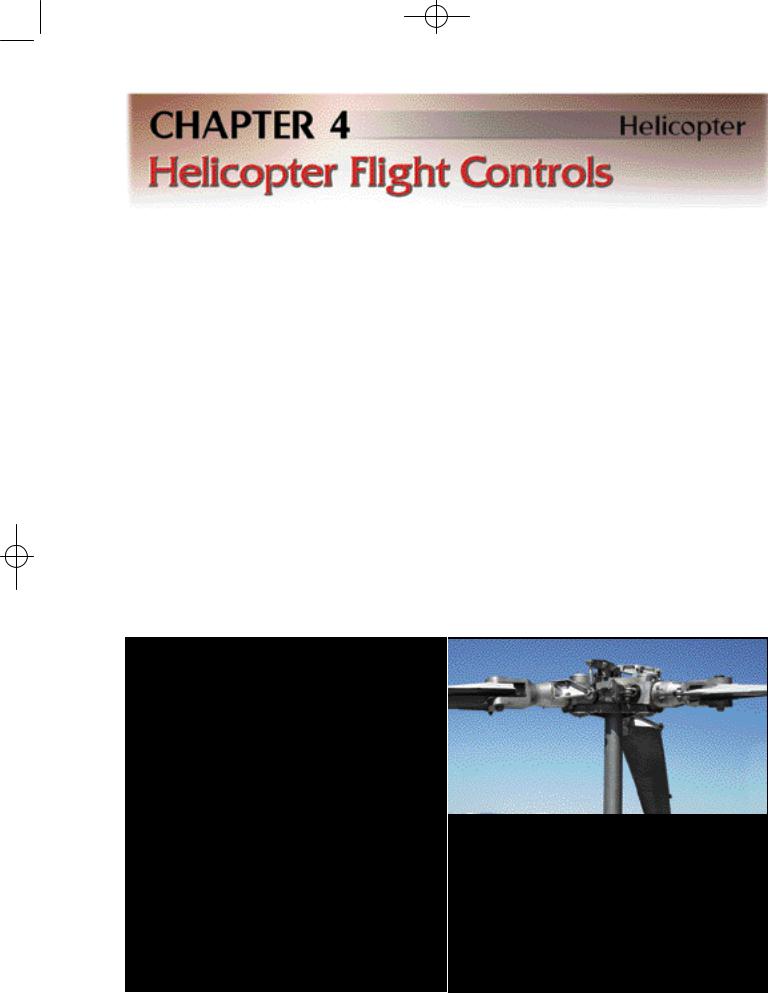
The collective pitch control, located on the left side of the pilot’s seat, changes the pitch angle of all main rotor blades simultaneously, or collectively, as the name implies. As the collective pitch control is raised, there is a simultaneous and equal increase in pitch angle of all main rotor blades; as it is lowered, there is a simultaneous and equal decrease in pitch angle. This is done through a series of mechanical linkages and the amount of movement in the collective lever determines the
amount of blade pitch change. [Figure 4-1] An adjustable friction control helps prevent inadvertent collective pitch movement.
Changing the pitch angle on the blades changes the angle of attack on each blade. With a change in angle of attack comes a change in drag, which affects the speed or r.p.m. of the main rotor. As the pitch angle increases, angle of attack increases, drag increases, and rotor r.p.m. decreases. Decreasing pitch angle decreases both angle of attack and drag, while rotor r.p.m. increases. In order to maintain a constant rotor r.p.m., which is essential in helicopter operations, a proportionate change in power is required to compensate for the change in drag. This is accomplished with the throttle control or a correlator and/or governor, which automatically adjusts engine power.
Figure 4-1. Raising the collective pitch control increases the pitch angle the same amount on all blades.
Ch 04.qxd 7/15/2003 9:10 AM Page 4-2
Figure 4-2. A twist grip throttle is usually mounted on the end of the collective lever. Some turbine helicopters have the throttles mounted on the overhead panel or on the floor in the cockpit.
THROTTLE CONTROL
The function of the throttle is to regulate engine r.p.m. If the correlator or governor system does not maintain the desired r.p.m. when the collective is raised or lowered, or if those systems are not installed, the throttle has to be moved manually with the twist grip in order to maintain r.p.m. Twisting the throttle outboard increases r.p.m.; twisting it inboard decreases r.p.m. [Figure 4-2]
COLLECTIVE PITCH / THROTTLE COORDINATION
When the collective pitch is raised, the load on the engine is increased in order to maintain desired r.p.m. The load is measured by a manifold pressure gauge in piston helicopters or by a torque gauge in turbine helicopters.
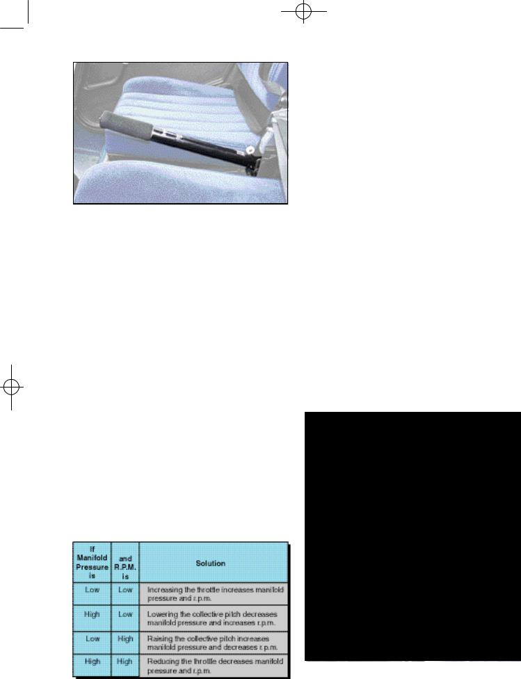
In piston helicopters, the collective pitch is the primary control for manifold pressure, and the throttle is the primary control for r.p.m. However, the collective pitch control also influences r.p.m., and the throttle also influences manifold pressure;
therefore, each is considered to be a secondary control of the other’s function. Both the tachometer (r.p.m. indicator) and the manifold pressure gauge must be analyzed to determine which control to use. Figure 4-3 illustrates this relationship.
CORRELATOR / GOVERNOR
A correlator is a mechanical connection between the collective lever and the engine throttle. When the collective lever is raised, power is automatically increased and when lowered, power is decreased. This system maintains r.p.m. close to the desired value, but still requires adjustment of the throttle for fine tuning.
A governor is a sensing device that senses rotor and engine r.p.m. and makes the necessary adjustments in order to keep rotor r.p.m. constant. In normal operations, once the rotor r.p.m. is set, the governor keeps the r.p.m. constant, and there is no need to make any throttle adjustments. Governors are common on all turbine helicopters and used on some piston powered helicopters.
Some helicopters do not have correlators or governors and require coordination of all collective and throttle movements. When the collective is raised, the throttle must be increased; when the collective is lowered, the throttle must be decreased. As with any aircraft control, large adjustments of either collective pitch or throttle
Figure 4-3. Relationship between manifold pressure, r.p.m., collective, and throttle.
Figure 4-4. The cyclic pitch control may be mounted vertically between the pilot’s knees or on a teetering bar from a single cyclic located in the center of the helicopter. The cyclic can pivot in all directions.
Ch 04.qxd 7/15/2003 9:10 AM Page 4-3
should be avoided. All corrections should be made through the use of smooth pressure.
CYCLIC PITCH CONTROL
The cyclic pitch control tilts the main rotor disc by changing the pitch angle of the rotor blades in their cycle of rotation. When the main rotor disc is tilted, the horizontal component of lift moves the helicopter in the direction of tilt. [Figure 4-4]
The rotor disc tilts in the direction that pressure is applied to the cyclic pitch control. If the cyclic is moved forward, the rotor disc tilts forward; if the cyclic is moved aft, the disc tilts aft, and so on. Because the rotor disc acts like a gyro, the mechanical linkages for the cyclic control rods are rigged in such a way that they decrease the pitch angle of the rotor blade approximately 90° before it reaches the direction of cyclic displacement, and increase the pitch angle of the rotor blade approximately 90° after it passes the direction of displacement. An increase in pitch angle increases angle of attack; a decrease in pitch angle decreases angle of attack. For example, if the cyclic is moved forward, the angle of attack decreases as the rotor blade passes the right side of the helicopter and increases on the left side. This results in maximum downward deflection of the rotor blade in front of the helicopter and maximum
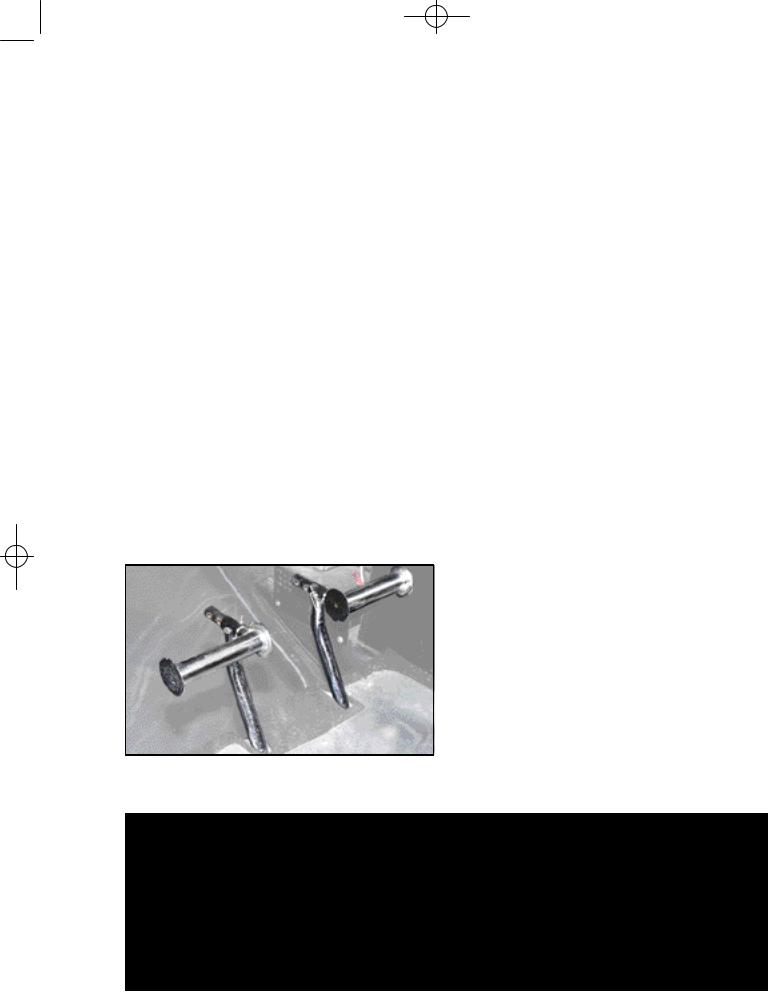
Figure 4-5. Antitorque pedals compensate for changes in torque and control heading in a hover.
upward deflection behind it, causing the rotor disc to tilt forward.
ANTITORQUE PEDALS
The antitorque pedals, located on the cabin floor by the pilot’s feet, control the pitch, and therefore the thrust, of the tail rotor blades. [Figure 4-5] . The main purpose of the tail rotor is to counteract the torque effect of the main rotor. Since torque varies with changes in power, the tail rotor thrust must also be varied. The pedals are connected to the pitch change mechanism on the tail rotor gearbox and allow the pitch angle on the tail rotor blades to be increased or decreased.
HEADING CONTROL
Besides counteracting torque of the main rotor, the tail rotor is also used to control the heading of the helicopter while hovering or when making hovering turns. Hovering turns are commonly referred to as “pedal turns.”
In forward flight, the antitorque pedals are not used to control the heading of the helicopter, except during portions of crosswind takeoffs and approaches. Instead they are used to compensate for torque to put the helicopter in longitudinal trim so that coordinated flight can be maintained. The cyclic control is used to change heading by making a turn to the desired direction.
The thrust of the tail rotor depends on the pitch angle of the tail rotor blades. This pitch angle can be positive, negative, or zero. A positive pitch angle tends to move the tail to the right. A negative pitch angle moves the tail to the left, while no thrust is produced with a zero pitch angle.
With the right pedal moved forward of the neutral position, the tail rotor either has a negative pitch angle or a small positive pitch angle. The farther it is forward, the larger the negative pitch angle. The nearer it is to neutral, the more positive the pitch angle, and somewhere in between, it has a zero pitch angle. As the left pedal is moved forward of
Figure 4-6. Tail rotor pitch angle and thrust in relation to pedal positions during cruising flight.

Ch 04.qxd 7/15/2003 9:10 AM Page 4-4
the neutral position, the positive pitch angle of the tail rotor increases until it becomes maximum with full forward displacement of the left pedal.
If the tail rotor has a negative pitch angle, tail rotor thrust is working in the same direction as the torque of the main rotor. With a small positive pitch angle, the tail rotor does not produce sufficient thrust to overcome the torque effect of the main rotor during cruise flight. Therefore, if the right pedal is displaced forward of neutral during cruising flight, the tail rotor thrust does not overcome
the torque effect, and the nose yaws to the right. [Figure 4-6]
With the antitorque pedals in the neutral position, the tail rotor has a medium positive pitch angle. In medium positive pitch, the tail rotor thrust approximately equals the torque of the main rotor during cruise flight, so the helicopter maintains a constant heading in level flight.
If the left pedal is in a forward position, the tail rotor has a high positive pitch position. In this position, tail rotor thrust exceeds the thrust needed to

Ch 05.qxd 7/15/2003 9:10 AM Page 5-1
By knowing the various systems on a helicopter, you will be able to more easily recognize potential problems, and if a problem arises, you will have a better understanding of what to do to correct the situation.
ENGINES
The two most common types of engines used in helicopters are the reciprocating engine and the turbine engine. Reciprocating engines, also called piston engines, are generally used in smaller helicopters. Most training helicopters use reciprocating engines because they are relatively simple and inexpensive to operate. Turbine engines are more powerful and are used in a wide variety of helicopters. They produce a tremendous amount of power for their size but are generally more expensive to operate.
RECIPROCATING ENGINE
The reciprocating engine consists of a series of pistons connected to a rotating crankshaft. As the pistons move up and down, the crankshaft rotates. The reciprocating engine gets its name from the back-and-forth movement of its internal parts. The four-stroke engine is the most common type, and refers to the four different cycles the engine undergoes to produce power. [Figure 5-1]
When the piston moves away from the cylinder head on the intake stroke, the intake valve opens and a mixture of fuel and air is drawn into the combustion chamber. As the cylinder moves back towards the cylinder head, the intake valve closes, and the fuel/air mixture is compressed. When compression is nearly complete, the spark plugs fire and the compressed mixture is ignited to begin the power stroke. The rapidly expanding gases from the controlled burning of the fuel/air mixture drive the piston away from the cylinder head, thus providing power to rotate the crankshaft. The piston then moves back toward the cylinder head on the exhaust stroke where the burned gasses are expelled through the opened exhaust valve.
Even when the engine is operated at a fairly low speed, the four-stroke cycle takes place several
Figure 5-1. The arrows in this illustration indicate the direction of motion of the crankshaft and piston during the four-stroke cycle.
hundred times each minute. In a four-cylinder engine, each cylinder operates on a different stroke. Continuous rotation of a crankshaft is maintained by the precise timing of the power strokes in each cylinder.
TURBINE ENGINE
The gas turbine engine mounted on most helicopters is made up of a compressor, combustion chamber, turbine, and gearbox assembly. The compressor compresses the air, which is then fed
Ch 05.qxd 7/15/2003 9:10 AM Page 5-2
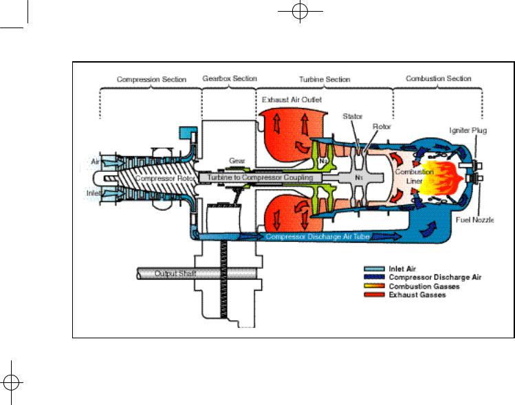
Figure 5-2. Many helicopters use a turboshaft engine to drive the main transmission and rotor systems. The main difference between a turboshaft and a turbojet engine is that most of the energy produced by the expanding gases is used to drive a turbine rather than producing thrust through the expulsion of exhaust gases.
into the combustion chamber where atomized fuel is injected into it. The fuel/air mixture is ignited and allowed to expand. This combustion gas is then forced through a series of turbine wheels causing them to turn. These turbine wheels provide power to both the engine compressor and the main rotor system through an output shaft. The combustion gas is finally expelled through an exhaust outlet. [Figure 5-2]
COMPRESSOR
The compressor may consist of an axial compressor, a centrifugal compressor, or both. An axial compressor consists of two main elements, the rotor and the stator. The rotor consists of a number of blades fixed on a rotating spindle and resembles a fan. As the rotor turns, air is drawn rearwards. Stator vanes are arranged in fixed rows between the rotor blades and act as a diffuser at each stage to decrease air velocity and increase air pressure. There may be a number of rows of rotor blades and stator vanes. Each row constitutes a pressure stage, and the number of stages depends on the amount of air and pressure rise required for the particular engine.
forged disc with integral blades, rotates at a high speed to draw air in and expel it at an accelerated rate. The air then passes through the diffuser which slows the air down. When the velocity of the air is slowed, static pressure increases, resulting in compressed, high-pressure air. The high pressure air then passes through the compressor manifold where it is distributed to the combustion chamber.
COMBUSTION CHAMBER
Unlike a piston engine, the combustion in a turbine engine is continuous. An igniter plug serves only to ignite the fuel/air mixture when starting the engine. Once the fuel/air mixture is ignited, it will continue to burn as long as the fuel/air mixture continues to be present. If there is an interruption of fuel, air, or both, combustion ceases. This is known as a “flame-out,” and the engine has to be restarted or re-lit. Some helicopters are equipped with auto-relight, which automatically activates the igniters to start combustion if the engine flames out.
TURBINE
A centrifugal compressor consists of an impeller, diffuser, and a manifold. The impeller, which is a
The turbine section consists of a series of turbine wheels that are used to drive the compressor

Ch 05.qxd 7/15/2003 9:10 AM Page 5-3
section and the rotor system. The first stage, which is usually referred to as the gas producer or N1 may consist of one or more turbine wheels. This stage drives the components necessary to complete the turbine cycle making the engine self-sustaining. Common components driven by the N1 stage are the compressor, oil pump, and fuel pump. The second stage, which may also consist of one or more wheels, is dedicated to driving the main rotor system and accessories from the engine gearbox. This is referred to as the power turbine (N2 or Nr).
If the first and second stage turbines are mechanically coupled to each other, the system is said to be a direct-drive engine or fixed turbine. These engines share a common shaft, which means the first and second stage turbines, and thus the compressor and output shaft, are connected.
On most turbine assemblies used in helicopters, the first stage and second stage turbines are not mechanically connected to each other. Rather, they are mounted on independent shafts and can turn freely with respect to each other. This is referred to as a “free turbine.” When the engine is running, the combustion gases pass through the first stage turbine to drive the compressor rotor, and then past the independent second stage turbine, which turns the gearbox to drive the output shaft.
TRANSMISSION SYSTEM
The transmission system transfers power from the engine to the main rotor, tail rotor, and other accessories. The main components of the transmission system are the main rotor transmission, tail rotor drive system, clutch, and freewheeling unit. Helicopter transmissions are normally lubricated and cooled with their own oil supply. A sight gauge is provided to check the oil level. Some transmissions have chip detectors located in the sump. These detectors are wired to warning lights located on the pilot’s instrument panel that illuminate in the event of an internal problem.
nate when ferrous metal particles are picked up.
Chip Detector—A chip detector is a warning device that alerts you to any abnormal wear in a transmission or engine. It consists of a magnetic plug located within the transmission. The magnet attracts any ferrous metal particles that have come loose from the bearings or other transmis - sion parts. Most chip detectors send a signal to lights located on the instrument panel that illumi-
Figure 5-3. There are various types of dual-needle tachometers, however, when the needles are superimposed or married, the ratio of the engine r.p.m. is the same as the gear reduction ratio.
MAIN ROTOR TRANSMISSION
The primary purpose of the main rotor transmission is to reduce engine output r.p.m. to optimum rotor r.p.m. This reduction is different for the various helicopters, but as an example, suppose the engine r.p.m. of a specific helicopter is 2,700. To achieve a rotor speed of 450 r.p.m. would require a 6 to 1 reduction. A 9 to 1 reduction would mean the rotor would turn at 300 r.p.m.
Most helicopters use a dual-needle tachometer to show both engine and rotor r.p.m. or a percentage of engine and rotor r.p.m. The rotor r.p.m. needle normally is used only during clutch engagement to monitor rotor acceleration, and in autorotation to
Figure 5-4. The typical components of a tail rotor drive system
are shown here.