

Rotorcraft Flying Handbook
.pdfFront Matter.qxd 7/15/2003 2:25 PM Page x
Hang Test ...................................................... |
19-4 |
Chapter 20—Flight Operations |
|
Preflight ......................................................... |
20-1 |
Cockpit Management ................................ |
20-1 |
Engine Starting .............................................. |
20-1 |
Taxiing ........................................................... |
20-1 |
Blade Flap ................................................. |
20-1 |
Before Takeoff ............................................... |
20-2 |
Prerotation ................................................. |
20-2 |
Takeoff ........................................................... |
20-3 |
Normal Takeoff .......................................... |
20-3 |
Crosswind Takeoff ..................................... |
20-4 |
Common Errors for Normal and |
|
Crosswind Takeoffs ................................... |
20-4 |
Short-Field Takeoff .................................... |
20-4 |
Common Errors..................................... |
20-4 |
High-Altitude Takeoff ............................. |
20-4 |
Soft-Field Takeoff ...................................... |
20-5 |
Common Errors..................................... |
20-5 |
Jump Takeoff......................................... |
20-5 |
Basic Flight Maneuvers................................. |
20-6 |
Straight-and-Level Flight ........................... |
20-6 |
Climbs ....................................................... |
20-6 |
Descents ................................................... |
20-7 |
Turns ......................................................... |
20-7 |
Slips ...................................................... |
20-7 |
Skids............................................................. |
|
20-7 |
|
Common Errors During Basic |
|
Flight Maneuvers....................................... |
20-8 |
Steep Turns ............................................... |
20-8 |
Common Errors..................................... |
20-8 |
Ground Reference Maneuvers...................... |
20-8 |
Rectangular Course .................................. |
20-8 |
S-Turns ............................................................. |
|
20-10 |
|
Turns Around a Point............................... |
20-11 |
Common Errors During |
|
Ground Reference Maneuvers ................ |
20-11 |
Flight at Slow Airspeeds.............................. |
20-12 |
Common Errors....................................... |
20-12 |
High Rate of Descent .................................. |
20-12 |
Common Errors....................................... |
20-13 |
Landings...................................................... |
20-13 |
Normal Landing....................................... |
20-13 |
Short-Field Landing................................. |
20-13 |
Soft-Field Landing ................................... |
20-14 |
Crosswind Landing.................................. |
20-14 |
High-Altitude Landing .............................. |
20-14 |
Common Errors During Landing ............. |
20-15 |
Go-Around ................................................... |
20-15 |
Common Errors....................................... |
20-15 |
After Landing and Securing......................... |
20-15 |
Chapter 21—Gyroplane Emergencies |
|
Aborted Takeoff ............................................. |
21-1 |
Accelerate/Stop Distance .......................... |
21-1 |
Lift-off at Low Airspeed and |
|
High Angle of Attack ...................................... |
21-1 |
Common Errors......................................... |
21-2 |
Pilot-Induced Oscillation (PIO) ...................... |
21-2 |
Buntover (Power Pushover) .......................... |
21-3 |
Ground Resonance ....................................... |
21-3 |
Emergency Approach and Landing............... |
21-3 |
Emergency Equipment and Survival Gear .... |
21-4 |
Chapter 22—Gyroplane Aeronautical Decision |
|
Making |
|
Impulsivity...................................................... |
22-1 |
Invulnerability ................................................ |
22-1 |
Macho............................................................ |
22-2 |
Resignation ................................................... |
22-2 |
Anti-Authority................................................. |
22-3 |
Glossary ......................................................... |
G-1 |
Index ................................................................. |
I-1 |

Ch 01.qxd 7/15/2003 9:07 AM Page 1-1
Helicopters come in many sizes and shapes, but most share the same major components. These components include a cabin where the payload and crew are carried; an airframe, which houses the various components, or where components are attached; a powerplant or engine; and a transmission, which, among other things, takes the power from the engine and transmits it to the main rotor, which provides the aerodynamic forces that make the helicopter fly. Then, to keep the helicopter from turning due to torque, there must be some type of antitorque system. Finally there is the landing gear, which could be skids, wheels, skis, or
Figure 1-1. The major components of a helicopter are the cabin, airframe, landing gear, powerplant, transmission, main rotor system, and tail rotor system.
floats. This chapter is an introduction to these components. [Figure 1-1]
THE MAIN ROTOR SYSTEM
The rotor system found on helicopters can consist of a single main rotor or dual rotors. With most dual rotors, the rotors turn in opposite directions so the torque from one rotor is opposed by the torque of the other. This cancels the turning tendencies. [Figure 1-2]
In general, a rotor system can be classified as either fully articulated, semirigid, or rigid. There are variations and combinations of these systems, which will be discussed in greater detail in Chapter 5—Helicopter Systems.
FULLY ARTICULATED ROTOR SYSTEM
A fully articulated rotor system usually consists of three or more rotor blades. The blades are allowed to flap, feather, and lead or lag independently of each other. Each rotor blade is attached to the rotor hub by a horizontal hinge, called the flapping hinge, which permits the blades to flap up and down. Each blade can move up and down
Figure 1-2. Helicopters can have a single main rotor or a dual rotor system.
Payload—The term used for passengers, baggage, and cargo.
Torque—In helicopters with a single, main rotor system, the tendency of the helicopter to turn in the opposite direction of the main rotor rotation.
Blade Flap—The upward or downward movement of the rotor blades during rotation.
Blade Feather or Feathering— The rotation of the blade around the spanwise (pitch change) axis.
Blade Lead or Lag—The fore and aft movement of the blade in the plane of rotation. It is sometimes called hunting or dragging.

Ch 01.qxd 7/15/2003 9:07 AM Page 1-2
independently of the others. The flapping hinge may be located at varying distances from the rotor hub, and there may be more than one. The position is chosen by each manufacturer, primarily with regard to stability and control.
Each rotor blade is also attached to the hub by a vertical hinge, called a drag or lag hinge, that permits each blade, independently of the others, to move back and forth in the plane of the rotor disc. Dampers are normally incorporated in the design of this type of rotor system to prevent excessive motion about the drag hinge. The purpose of the drag hinge and dampers is to absorb the acceleration and deceleration of the rotor blades.
The blades of a fully articulated rotor can also be feathered, or rotated about their spanwise axis. To put it more simply, feathering means the changing of the pitch angle of the rotor blades.
SEMIRIGID ROTOR SYSTEM
A semirigid rotor system allows for two different movements, flapping and feathering. This system is normally comprised of two blades, which are rigidly attached to the rotor hub. The hub is then attached to the rotor mast by a trunnion bearing or teetering hinge. This allows the blades to see-saw or flap together. As one blade flaps down, the other flaps up. Feathering is accomplished by the feathering hinge, which changes the pitch angle of the blade.
RIGID ROTOR SYSTEM
The rigid rotor system is mechanically simple, but structurally complex because operating loads must be absorbed in bending rather than through hinges. In this system, the blades cannot flap or lead and lag, but they can be feathered.
Figure 1-3. The antitorque rotor produces thrust to oppose torque and helps prevent the helicopter from turning in the opposite direction of the main rotor.
ANTITORQUE SYSTEMS
TAIL ROTOR
Most helicopters with a single, main rotor system require a separate rotor to overcome torque. This is accomplished through a variable pitch, antitorque rotor or tail rotor. [Figure 1-3]. You will need to vary the thrust of the antitorque system to maintain directional control whenever the main rotor torque changes, or to make heading changes while hovering.
Figure 1-4. Compared to an unprotected tail rotor, the fenestron antitorque system provides an improved margin of safety during ground operations.
FENESTRON
Another form of antitorque rotor is the fenestron or “fan-in-tail” design. This system uses a series of rotating blades shrouded within a vertical tail. Because the blades are located within a circular duct, they are less likely to come into contact with people or objects. [Figure 1-4]
NOTAR®
The NOTAR® system is an alternative to the antitorque rotor. The system uses low-pressure air that is forced into the tailboom by a fan mounted within the helicopter. The air is then fed through horizontal slots, located on the right side of the tailboom, and to a controllable rotating nozzle to provide antitorque and directional control. The low-pressure air coming from the horizontal slots, in conjunction with the downwash from the main rotor, creates a phenomenon called “Coanda Effect,” which produces a lifting force on the right side of the tailboom. [Figure 1-5]
LANDING GEAR
The most common landing gear is a skid type gear, which is suitable for landing on various types of surfaces. Some types of skid gear are equipped with dampers so touchdown shocks or jolts are not transmitted to the main rotor system. Other types

Ch 01.qxd 7/15/2003 9:07 AM Page 1-3
Figure 1-5. While in a hover, Coanda Effect supplies approximately two-thirds of the lift necessary to maintain directional control. The rest is created by directing the thrust from the controllable rotating nozzle.
absorb the shocks by the bending of the skid attachment arms. Landing skids may be fitted with replaceable heavy-duty skid shoes to protect them from excessive wear and tear.
Helicopters can also be equipped with floats for water operations, or skis for landing on snow or soft terrain. Wheels are another type of landing gear. They may be in a tricycle or four point configuration. Normally, the nose or tail gear is free to swivel as the helicopter is taxied on the ground.
Figure 1-6. Typically, the engine drives the main rotor through a transmission and belt drive or centrifugal clutch system. The antitorque rotor is driven from the transmission.
POWERPLANT
A typical small helicopter has a reciprocating engine, which is mounted on the airframe. The engine can be mounted horizontally or vertically with the transmission supplying the power to the vertical main rotor shaft. [Figure 1-6]
Another engine type is the gas turbine. This engine is used in most medium to heavy lift helicopters due to its large horsepower output. The engine drives the main transmission, which then transfers power directly to the main rotor system, as well as the tail rotor.
Figure 1-7. Location of flight controls.

Ch 01.qxd 7/15/2003 9:07 AM Page 1-4
FLIGHT CONTROLS
When you begin flying a helicopter, you will use four basic flight controls. They are the cyclic pitch control; the collective pitch control; the throttle, which is usually a twist grip control located on the end of the collective lever; and the anti - torque pedals. The collective and cyclic controls the pitch of the main rotor blades. The function of these controls will be explained in detail in Chapter 4—Flight Controls. [Figure 1-7]

Ch 02.qxd 7/15/2003 9:08 AM Page 2-1
There are four forces acting on a helicopter in flight. They are lift, weight, thrust, and drag. [Figure 2-1] Lift is the upward force created by the effect of airflow as it passes around an airfoil. Weight opposes lift and is caused by the downward pull of gravity. Thrust is the force that propels the helicopter through the air. Opposing lift and thrust is drag, which is the retarding force created
Figure 2-2. The upper and lower curvatures are the same on a symmetrical airfoil and vary on an asymmetrical airfoil.
Figure 2-1. Four forces acting on a helicopter in forward flight.
by development of lift and the movement of an object through the air.
AIRFOIL
Before beginning the discussion of lift, you need to be aware of certain aerodynamic terms that describe an airfoil and the interaction of the airflow around it.
An airfoil is any surface, such as an airplane wing or a helicopter rotor blade, which provides aerodynamic force when it interacts with a moving stream of air. Although there are many different rotor blade airfoil designs, in most helicopter flight conditions, all airfoils perform in the same manner.
Engineers of the first helicopters designed relatively thick airfoils for their structural characteristics. Because the rotor blades were very long and slender, it was necessary to incorporate more structural rigidity into them. This prevented exces-
sive blade droop when the rotor system was idle, and minimized blade twisting while in flight. The airfoils were also designed to be symmetrical, which means they had the same camber (curvature) on both the upper and lower surfaces. Symmetrical blades are very stable, which helps keep blade twisting and flight control loads to a minimum. [Figure 2-2] This stability is achieved by keeping the center of pressure virtually unchanged as the angle of attack changes. Center of pressure is the imaginary point on the chord line where the resultant of all aerodynamic forces are considered to be concentrated.
Today, designers use thinner airfoils and obtain the required rigidity by using composite materials. In addition, airfoils are asymmetrical in design, meaning the upper and lower surface do not have the same camber. Normally these airfoils would not be as stable, but this can be corrected by bending the trailing edge to produce the same characteristics as symmetrical airfoils. This is called “reflexing.” Using this type of rotor blade allows the rotor system to operate at higher forward speeds.
One of the reasons an asymmetrical rotor blade is not as stable is that the center of pressure changes with changes in angle of attack. When the center of pressure lifting force is behind the pivot point on a rotor blade, it tends to cause the rotor disc to pitch up. As the angle of attack increases, the center of pressure moves forward.
If it moves ahead of the pivot point, the pitch of the
Ch 02.qxd 7/15/2003 9:08 AM Page 2-2
Figure 2-3. Aerodynamic terms of an airfoil.
rotor disc decreases. Since the angle of attack of the rotor blades is constantly changing during each cycle of rotation, the blades tend to flap, feather, lead, and lag to a greater degree.
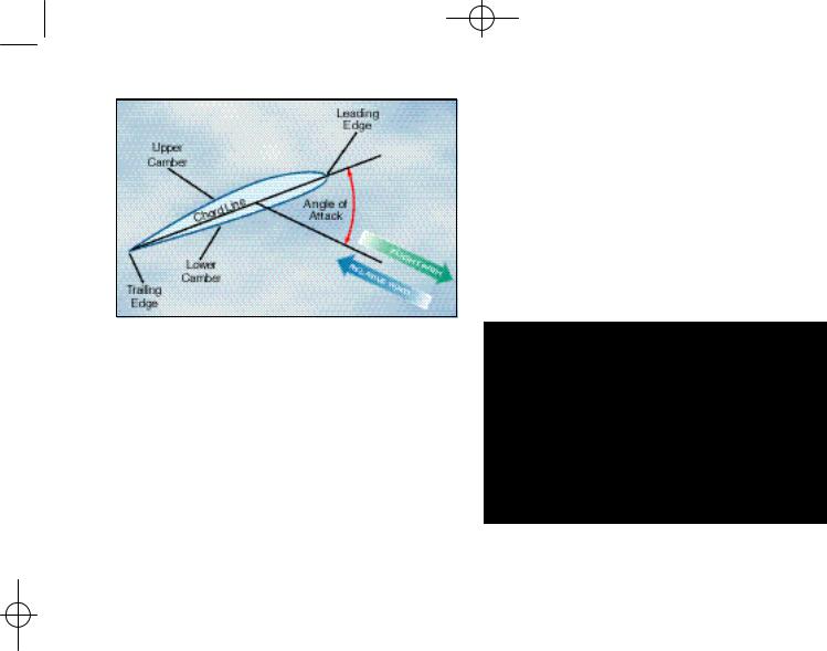
When referring to an airfoil, the span is the distance from the rotor hub to the blade tip. Blade twist refers to a changing chord line from the blade root to the tip. Twisting a rotor blade causes it to produce a more even amount of lift along its span. This is necessary because rotational velocity increases toward the blade tip. The leading edge is the first part of the airfoil to meet the oncoming air. [Figure 2-3] The trailing edge is the aft portion where the airflow over the upper surface joins the airflow under the lower surface. The chord line is an imaginary straight line drawn from the leading to the trailing edge. The camber is the curvature of the airfoil’s upper and lower surfaces. The relative wind is the wind moving past the airfoil. The direction of this wind is relative to the attitude, or position, of the airfoil and is always parallel, equal, and opposite in direction to the flight path of the airfoil. The angle of attack is the angle between the blade chord line and the direction of the relative wind.
RELATIVE WIND
Relative wind is created by the motion of an airfoil through the air, by the motion of air past an airfoil, or by a combination of the two. Relative wind may be affected by several factors, including the rotation of the rotor blades, horizontal movement of the helicopter, flapping of the rotor blades, and wind speed and direction.
Axis-of-Rotation—The imaginary |
Tip-Path Plane—The imaginary |
line about which the rotor rotates. |
circular plane outlined by the |
It is represented by a line drawn |
rotor blade tips as they make a |
through the center of, and per- |
cycle of rotation. |
pendicular to, the tip-path plane. |
|
For a helicopter, the relative wind is the flow of air with respect to the rotor blades. If the rotor is stopped, wind blowing over the blades creates a relative wind. When the helicopter is hovering in a no-wind condition, relative wind is created by the motion of the rotor blades through the air. If the helicopter is hovering in a wind, the relative wind is a combination of the wind and the motion of the rotor blades through the air. When the helicopter is in forward flight, the relative wind is a combination of the rotation of the rotor blades and the forward speed of the helicopter.
Figure 2-4. Do not confuse the axis of rotation with the rotor mast. The only time they coincide is when the tip-path plane is perpendicular to the rotor mast.
BLADE PITCH ANGLE
The pitch angle of a rotor blade is the angle between its chord line and the reference plane containing the rotor hub. [Figure 2-4] You control the pitch angle of the blades with the flight controls. The collective pitch changes each rotor blade an equal amount of pitch no matter where it is located in the plane of rotation (rotor disc) and is used to change rotor thrust. The cyclic pitch control changes the pitch of each blade as a function of where it is in the plane of rotation. This allows for trimming the helicopter in pitch and roll during forward flight and for maneuvering in all flight conditions.
ANGLE OF ATTACK
When the angle of attack is increased, air flowing over the airfoil is diverted over a greater distance, resulting in an increase of air velocity and more lift. As angle of attack is increased further, it becomes more difficult for air to flow smoothly across the top of the airfoil. At this point the airflow begins to separate from the airfoil and enters a burbling or turbulent pattern. The turbulence
Aircraft Pitch—When referenced |
the nose of the helicopter to |
to a helicopter, is the movement |
move up or down. |
of the helicopter about its lateral, |
|
or side to side axis. Movement of |
Aircraft Roll—Is the movement of |
the cyclic forward or aft causes |
the helicopter about its longitudi- |
|
nal, or nose to tail axis. |

Ch 02.qxd 7/15/2003 9:08 AM Page 2-3
Figure 2-5. As the angle of attack is increased, the separation point starts near the trailing edge of the airfoil and progresses forward. Finally, the airfoil loses its lift and a stall condition occurs.
Figure 2-6. Angle of attack may be greater than, less than, or the same as the pitch angle.
results in a large increase in drag and loss of lift in the area where it is taking place. Increasing the angle of attack increases lift until the critical angle of attack is reached. Any increase in the angle of attack beyond this point produces a stall and a rapid decrease in lift. [Figure 2-5]
Angle of attack should not be confused with pitch angle. Pitch angle is determined by the direction of the relative wind. You can, however, change the angle of attack by changing the pitch angle through the use of the flight controls. If the pitch angle is increased, the angle of attack is increased, if the pitch angle is reduced, the angle of attack is reduced. [Figure 2-6]
Figure 2-7. Magnus Effect is a lifting force produced when a rotating cylinder produces a pressure differential. This is the same effect that makes a baseball curve or a golf ball slice.
LIFT
MAGNUS EFFECT
The explanation of lift can best be explained by looking at a cylinder rotating in an airstream. The local velocity near the cylinder is composed of the airstream velocity and the cylinder’s rotational velocity, which decreases with distance from the cylinder. On a cylinder, which is rotating in such a way that the top surface area is rotating in the same direction as the airflow, the local velocity at the surface is high on top and low on the bottom.
As shown in figure 2-7, at point “A,” a stagnation point exists where the airstream line that impinges on the surface splits; some air goes over and some under. Another stagnation point exists at
Figure 2-8. Air circulation around an airfoil occurs when the front stagnation point is below the leading edge and the aft stagnation point is beyond the trailing edge.
“B,” where the two air streams rejoin and resume at identical velocities. We now have upwash ahead of the rotating cylinder and downwash at the rear.

Ch 02.qxd 7/15/2003 9:08 AM Page 2-4
Figure 2-9. The upper surface of an airfoil is similar to the constriction in a venturi tube.
The difference in surface velocity accounts for a difference in pressure, with the pressure being lower on the top than the bottom. This low pressure area produces an upward force known as the “Magnus Effect.” This mechanically induced circulation illustrates the relationship between circulation and lift.
An airfoil with a positive angle of attack develops air circulation as its sharp trailing edge forces the rear stagnation point to be aft of the trailing edge, while the front stagnation point is below the leading edge. [Figure 2-8]
Figure 2-10. Lift is produced when there is decreased pressure above and increased pressure below an airfoil.
BERNOULLI’S PRINCIPLE
Air flowing over the top surface accelerates. The airfoil is now subjected to Bernoulli’s Principle or the “venturi effect.” As air velocity increases through the constricted portion of a venturi tube, the pressure decreases. Compare the upper surface of an airfoil with the constriction in a venturi tube that is narrower in the middle than at the ends. [Figure 2- 9]
The upper half of the venturi tube can be replaced by layers of undisturbed air. Thus, as air flows over the upper surface of an airfoil, the camber of
the airfoil causes an increase in the speed of the airflow. The increased speed of airflow results in a decrease in pressure on the upper surface of the airfoil. At the same time, air flows along the lower surface of the airfoil, building up pressure. The combination of decreased pressure on the upper surface and increased pressure on the lower surface results in an upward force. [Figure 2-10]
As angle of attack is increased, the production of lift is increased. More upwash is created ahead of the airfoil as the leading edge stagnation point moves under the leading edge, and more downwash is created aft of the trailing edge. Total lift now being produced is perpendicular to relative wind. In summary, the production of lift is based upon the airfoil creating circulation in the airstream (Magnus Effect) and creating differential pressure on the airfoil (Bernoulli’s Principle).
NEWTON’S THIRD LAW OF MOTION
Additional lift is provided by the rotor blade’s lower surface as air striking the underside is deflected downward. According to Newton’s Third Law of Motion, “for every action there is an equal and opposite reaction,” the air that is deflected downward also produces an upward (lifting) reaction.
Since air is much like water, the explanation for this source of lift may be compared to the planing effect of skis on water. The lift which supports the water skis (and the skier) is the force caused by the impact pressure and the deflection of water from the lower surfaces of the skis.
Under most flying conditions, the impact pressure and the deflection of air from the lower surface of the rotor blade provides a comparatively small percentage of the total lift. The majority of lift is the result of decreased pressure above the blade, rather than the increased pressure below it.
WEIGHT
Normally, weight is thought of as being a known, fixed value, such as the weight of the helicopter, fuel, and occupants. To lift the helicopter off the ground vertically, the rotor system must generate enough lift to overcome or offset the total weight of the helicopter and its occupants. This is accomplished by increasing the pitch angle of the main rotor blades.
Steady-State Flight—A condition when an aircraft is in straight- and-level, unaccelerated flight, and all forces are in balance.

Ch 02.qxd 7/15/2003 9:08 AM Page 2-5
Figure 2-11. The load factor diagram allows you to calculate the amount of “G” loading exerted with various angle of bank.
The weight of the helicopter can also be influenced by aerodynamic loads. When you bank a helicopter while maintaining a constant altitude, the “G” load or load factor increases. Load factor is the ratio of the load supported by the main rotor system to the actual weight of the helicopter and its contents. In steady-state flight, the helicopter has a load factor of one, which means the main rotor system is supporting the actual total weight of the helicopter. If you increase the bank angle to 60°, while still maintaining a constant altitude, the load factor increases to two. In this case, the main rotor system has to support twice the weight of the helicopter and its contents. [Figure 2-11]
Disc loading of a helicopter is the ratio of weight to the total main rotor disc area, and is determined by dividing the total helicopter weight by the rotor disc area, which is the area swept by the blades of a rotor. Disc area can be found by using the span
of one rotor blade as the radius of a circle and then determining the area the blades encompass during a complete rotation. As the helicopter is maneuvered, disc loading changes. The higher the loading, the more power you need to maintain rotor speed.
THRUST
Thrust, like lift, is generated by the rotation of the main rotor system. In a helicopter, thrust can be forward, rearward, sideward, or vertical. The resultant of lift and thrust determines the direction of movement of the helicopter.
The solidity ratio is the ratio of the total rotor blade area, which is the combined area of all the main rotor blades, to the total rotor disc area. This ratio provides a means to measure the potential for a rotor system to provide thrust.
The tail rotor also produces thrust. The amount of thrust is variable through the use of the antitorque pedals and is used to control the helicopter’s yaw.
DRAG
The force that resists the movement of a helicopter through the air and is produced when lift is developed is called drag. Drag always acts parallel to the relative wind. Total drag is composed of three types of drag: profile, induced, and parasite.
PROFILE DRAG
Profile drag develops from the frictional resistance of the blades passing through the air. It does not change significantly with the airfoil’s angle of attack, but increases moderately when airspeed
Figure 2-12. It is easy to visualize the creation of form drag by examining the airflow around a flat plate. Streamlining decreases form drag by reducing the airflow separation.
Aircraft Yaw—The movement of the helicopter about its vertical axis.