

Rotorcraft Flying Handbook
.pdfCh 02.qxd 7/15/2003 9:08 AM Page 2-6
increases. Profile drag is composed of form drag and skin friction.
Figure 2-13. The formation of induced drag is associated with the downward deflection of the airstream near the rotor blade.
Form drag results from the turbulent wake caused by the separation of airflow from the surface of a structure. The amount of drag is related to both the size and shape of the structure that protrudes into the relative wind. [Figure 2-12]
Skin friction is caused by surface roughness. Even though the surface appears smooth, it may be quite rough when viewed under a microscope. A thin layer of air clings to the rough surface and creates small eddies that contribute to drag.
INDUCED DRAG
Induced drag is generated by the airflow circulation around the rotor blade as it creates lift. The high-pressure area beneath the blade joins the
low-pressure air above the blade at the trailing edge and at the rotor tips. This causes a spiral, or vortex, which trails behind each blade whenever lift is being produced. These vortices deflect the airstream downward in the vicinity of the blade, creating an increase in downwash. Therefore, the blade operates in an average relative wind that is inclined downward and rearward near the blade. Because the lift produced by the blade is perpendicular to the relative wind, the lift is inclined aft by the same amount. The component of lift that is acting in a rearward direction is induced drag. [Figure 2-13]
As the air pressure differential increases with an increase in angle of attack, stronger vortices form, and induced drag increases. Since the blade’s angle of attack is usually lower at higher airspeeds, and higher at low speeds, induced drag
Figure 2-14. The total drag curve represents the combined forces of parasite, profile, and induced drag; and is plotted against airspeed.
decreases as airspeed increases and increases as airspeed decreases. Induced drag is the major cause of drag at lower airspeeds.
PARASITE DRAG
Parasite drag is present any time the helicopter is moving through the air. This type of drag increases with airspeed. Nonlifting components of the helicopter, such as the cabin, rotor mast, tail, and landing
L/Dmax—The maximum ratio between total lift (L) and the total drag (D). This point provides the best glide speed. Any deviation from best glide speed increases drag and reduces the distance you can glide.
Ch 03.qxd 7/15/2003 9:08 AM Page 3-1
Once a helicopter leaves the ground, it is acted upon by the four aerodynamic forces. In this chapter, we will examine these forces as they relate to flight maneuvers.
POWERED FLIGHT
In powered flight (hovering, vertical, forward, sideward, or rearward), the total lift and thrust forces of a rotor are perpendicular to the tip-path plane or plane of rotation of the rotor.
HOVERING FLIGHT
For standardization purposes, this discussion assumes a stationary hover in a no-wind condition. During hovering flight, a helicopter maintains a constant position over a selected point, usually a few feet above the ground. For a helicopter to hover, the lift and thrust produced by the rotor system act straight up and must equal the weight and drag, which act straight down. While hovering, you can change the amount of main rotor thrust to maintain the desired hovering altitude. This is done by changing the angle of attack of the main rotor blades and by varying power, as needed. In
this case, thrust acts in the same vertical direction as lift. [Figure 3-1]
The weight that must be supported is the total weight of the helicopter and its occupants. If the amount of thrust is greater than the actual weight, the helicopter gains altitude; if thrust is less than weight, the helicopter loses altitude.
The drag of a hovering helicopter is mainly induced drag incurred while the blades are producing lift. There is, however, some profile drag on the blades as they rotate through the air. Throughout the rest of this discussion, the term “drag” includes both induced and profile drag.
An important consequence of producing thrust is torque. As stated before, for every action there is an equal and opposite reaction. Therefore, as the engine turns the main rotor system in a counterclockwise direction, the helicopter fuselage turns clockwise. The amount of torque is directly related to the amount of engine power being used to turn the main rotor system. Remember, as power changes, torque changes.
To counteract this torque-induced turning tendency, an antitorque rotor or tail rotor is incorporated into most helicopter designs. You can vary the amount of thrust produced by the tail rotor in relation to the amount of torque produced by the engine. As the engine supplies more power, the
Figure 3-1. To maintain a hover at a constant altitude, enough lift and thrust must be generated to equal the weight of the helicopter and the drag produced by the rotor blades.
Figure 3-2. A tail rotor is designed to produce thrust in a direction opposite torque. The thrust produced by the tail rotor is sufficient to move the helicopter laterally.
Ch 03.qxd 7/15/2003 9:08 AM Page 3-2
tail rotor must produce more thrust. This is done through the use of antitorque pedals.
TRANSLATING TENDENCY OR DRIFT
During hovering flight, a single main rotor helicopter tends to drift in the same direction as antitorque rotor thrust. This drifting tendency is called translating tendency. [Figure 3-2]
To counteract this drift, one or more of the following features may be used:
•The main transmission is mounted so that the rotor mast is rigged for the tip-path plane to have a built-in tilt opposite tail thrust, thus producing a small sideward thrust.
•Flight control rigging is designed so that the rotor disc is tilted slightly opposite tail rotor thrust when the cyclic is centered.
•The cyclic pitch control system is designed so that the rotor disc tilts slightly opposite tail rotor thrust when in a hover.
Counteracting translating tendency, in a helicopter with a counterclockwise main rotor system, causes
the left skid to hang lower while hovering. The oppo-
site is true for rotor systems turning clockwise when viewed from above.
should be smooth and not exaggerated. [Figure 3- 3]
CONING
In order for a helicopter to generate lift, the rotor blades must be turning. This creates a relative wind that is opposite the direction of rotor system rotation. The rotation of the rotor system creates centrifugal force (inertia), which tends to pull the blades straight outward from the main rotor hub. The faster the rotation, the greater the centrifugal force. This force gives the rotor blades their rigidity and, in turn, the strength to support the weight
Figure 3-4. Rotor blade coning occurs as the rotor blades begin to lift the weight of the helicopter. In a semirigid and rigid rotor sys-
tem, coning results in blade bending. In an articulated rotor system, the blades assume an upward angle through movement about the flapping hinges.
of the helicopter. The centrifugal force generated determines the maximum operating rotor r.p.m. due to structural limitations on the main rotor system.
As a vertical takeoff is made, two major forces are acting at the same time—centrifugal force acting outward and perpendicular to the rotor mast, and lift acting upward and parallel to the mast. The result of these two forces is that the blades assume a conical path instead of remaining in the plane perpendicular to the mast. [Figure 3-4]
Figure 3-3. Because the helicopter’s body has mass and is suspended from a single point (the rotor mast head), it tends to act much like a pendulum.
PENDULAR ACTION
Since the fuselage of the helicopter, with a single main rotor, is suspended from a single point and has considerable mass, it is free to oscillate either longitudinally or laterally in the same way as a pendulum. This pendular action can be exaggerated by over controlling; therefore, control movements
Centrifugal Force—The apparent force that an object moving along a circular path exerts on the body constraining the obect and that acts outwardy away from the center of rotation.
Ch 03.qxd 7/15/2003 9:08 AM Page 3-3
CORIOLIS EFFECT
(LAW OF CONSERVATION
OF ANGULAR MOMENTUM)
Coriolis Effect, which is sometimes referred to as conservation of angular momentum, might be compared to spinning skaters. When they extend their arms, their rotation slows down because the center of mass moves farther from the axis of rota-
that blade flaps downward, its center of mass moves further from the axis of rotation and blade deceleration takes place. [Figure 3-5] Keep in mind
Figure 3-6. Because of the underslung rotor, the center of mass remains approximately the same distance from the mast after the rotor is tilted.
Figure 3-5. The tendency of a rotor blade to increase or decrease its velocity in its plane of rotation due to mass movement is known as Coriolis Effect, named for the mathematician who made studies of forces generated by radial movements of mass on a rotating disc.
tion. When their arms are retracted, the rotation speeds up because the center of mass moves closer to the axis of rotation.
When a rotor blade flaps upward, the center of mass of that blade moves closer to the axis of rotation and blade acceleration takes place in order to conserve angular momentum. Conversely, when
that due to coning, a rotor blade will not flap below a plane passing through the rotor hub and perpendicular to the axis of rotation. The acceleration and deceleration actions of the rotor blades are absorbed by either dampers or the blade structure itself, depending upon the design of the rotor system.
Two-bladed rotor systems are normally subject to Coriolis Effect to a much lesser degree than are articulated rotor systems since the blades are generally “underslung” with respect to the rotor hub, and the change in the distance of the center of mass from the axis of rotation is small. [Figure 3-6] The hunting action is absorbed by the blades
Figure 3-7. Air circulation patterns change when hovering out of ground effect (OGE) and when hovering in ground effect (IGE).

Ch 03.qxd 7/15/2003 9:08 AM Page 3-4
Figure 3-8. Gyroscopic precession principle—when a force is applied to a spinning gyro, the maximum reaction occurs approximately 90° later in the direction of rotation.
through bending. If a two-bladed rotor system is not “underslung,” it will be subject to Coriolis Effect comparable to that of a fully articulated system.
GROUND EFFECT
When hovering near the ground, a phenomenon known as ground effect takes place. [Figure 3-7] This effect usually occurs less than one rotor diameter above the surface. As the induced airflow through the rotor disc is reduced by the surface friction, the lift vector increases. This allows a lower rotor blade angle for the same amount of lift, which reduces induced drag. Ground effect also restricts the generation of blade tip vortices due to the downward and outward airflow making a larger portion of the blade produce lift. When the helicopter gains altitude vertically, with no forward airspeed, induced airflow is no longer restricted, and the blade tip vortices increase with the decrease in outward airflow. As a result, drag increases which means a higher pitch angle, and more power is needed to move the air down through the rotor.
Ground effect is at its maximum in a no-wind condition over a firm, smooth surface. Tall grass, rough terrain, revetments, and water surfaces alter the airflow pattern, causing an increase in rotor tip vortices.
GYROSCOPIC PRECESSION
The spinning main rotor of a helicopter acts like a gyroscope. As such, it has the properties of gyroscopic action, one of which is precession. Gyroscopic precession is the resultant action or deflection of a spinning object when a force is
Figure 3-9. With a counterclockwise main rotor blade rotation, as each blade passes the 90° position on the left, the maximum increase in angle of attack occurs. As each blade passes the 90° position to the right, the maximum decrease in angle of attack occurs. Maximum deflection takes place 90° later—maximum upward deflection at the rear and maximum downward deflection at the front—and the tip-path plane tips forward.
applied to this object. This action occurs approximately 90° in the direction of rotation from the point where the force is applied. [Figure 3-8]
Let us look at a two-bladed rotor system to see how gyroscopic precession affects the movement of the tip-path plane. Moving the cyclic pitch control increases the angle of attack of one rotor blade with the result that a greater lifting force is applied at that point in the plane of rotation. This same control movement simultaneously decreases the angle of attack of the other blade the same amount, thus decreasing the lifting force

Ch 03.qxd 7/15/2003 9:08 AM Page 3-5
flap up; the blade with the decreased angle of attack tends to flap down. Because the rotor disk
Figure 3-10. To ascend vertically, more lift and thrust must be gen-
erated to overcome the forces of weight and the drag.
acts like a gyro, the blades reach maximum deflection at a point approximately 90° later in the plane of rotation. As shown in figure 3-9, the retreating blade angle of attack is increased and the advancing blade angle of attack is decreased resulting in a tipping forward of the tip-path plane, since maximum deflection takes place 90° later when the blades are at the rear and front, respectively. In a rotor system using three or more
blades, the movement of the cyclic pitch control changes the angle of attack of each blade an appropriate amount so that the end result is the same.
VERTICAL FLIGHT
Hovering is actually an element of vertical flight. Increasing the angle of attack of the rotor blades (pitch) while their velocity remains constant generates additional vertical lift and thrust and the helicopter ascends. Decreasing the pitch causes the helicopter to descend. In a no wind condition when lift and thrust are less than weight and drag, the helicopter descends vertically. If lift and thrust are greater than weight and drag, the helicopter ascends vertically. [Figure 3-10]
FORWARD FLIGHT
In or during forward flight, the tip-path plane is tilted forward, thus tilting the total lift-thrust force forward from the vertical. This resultant lift-thrust force can be resolved into two components—lift acting vertically upward and thrust acting horizontally in the direction of flight. In addition to lift and thrust, there is weight (the downward acting force) and drag (the rearward acting or retarding force of inertia and wind resistance). [Figure 3-11]
Figure 3-11. To transition into forward flight, some of the vertical thrust must be vectored horizontally. You initiate this by forward movement of the cyclic control.
Figure 3-12. Effective translational lift is easily recognized in actual flight by a transient induced aerodynamic vibration and increased performance of the helicopter.
In straight-and-level, unaccelerated forward flight, lift equals weight and thrust equals drag (straight- and-level flight is flight with a constant heading and at a constant altitude). If lift exceeds weight, the helicopter climbs; if lift is less than weight, the helicopter descends. If thrust exceeds drag, the helicopter speeds up; if thrust is less than drag, it slows down.
As the helicopter moves forward, it begins to lose altitude because of the lift that is lost as thrust is
Ch 03.qxd 7/15/2003 9:08 AM Page 3-6
diverted forward. However, as the helicopter begins to accelerate, the rotor system becomes more efficient due to the increased airflow. The result is excess power over that which is required to hover. Continued acceleration causes an even larger increase in airflow through the rotor disc and more excess power.
TRANSLATIONAL LIFT
Translational lift is present with any horizontal flow of air across the rotor. This increased flow is most noticeable when the airspeed reaches approximately 16 to 24 knots. As the helicopter accelerates through this speed, the rotor moves out of its vortices and is in relatively undisturbed air. The airflow is also now more horizontal, which reduces induced flow and drag with a corresponding increase in angle of attack and lift. The additional lift available at this speed is referred to as “effective translational lift” (ETL). [Figure 3-12]
When a single-rotor helicopter flies through translational lift, the air flowing through the main rotor and over the tail rotor becomes less turbulent and more aerodynamically efficient. As the tail rotor efficiency improves, more thrust is produced causing the aircraft to yaw left in a counterclockwise rotor system. It will be necessary to use right torque pedal to correct for this tendency on takeoff. Also, if no corrections are made, the nose rises or pitches up, and rolls to the right. This is caused by combined effects of dissymmetry of lift and transverse flow effect, and is corrected with cyclic control.
Translational lift is also present in a stationary hover if the wind speed is approximately 16 to 24 knots. In normal operations, always utilize the benefit of translational lift, especially if maximum performance is needed.
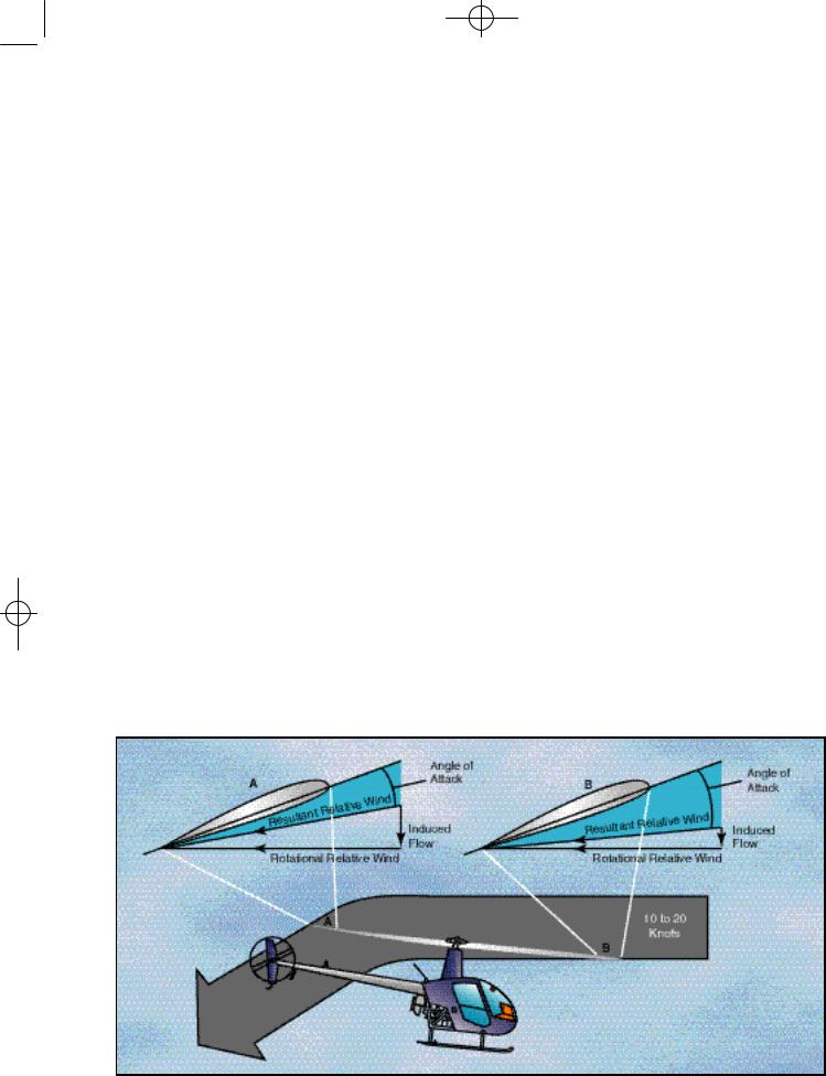
INDUCED FLOW
As the rotor blades rotate they generate what is called rotational relative wind. This airflow is characterized as flowing parallel and opposite the rotor’s plane of rotation and striking perpendicular to the rotor blade’s leading edge. This rotational relative wind is used to generate lift. As rotor blades produce lift, air is accelerated over the foil and projected downward. Anytime a helicopter is producing lift, it moves large masses of air vertically and down through the rotor system. This downwash or induced flow can significantly change the efficiency of the rotor system. Rotational relative wind combines with induced flow to form the resultant relative wind. As induced flow increases, resultant relative wind becomes less horizontal. Since angle of attack is determined by measuring the difference between the chord line and the resultant relative wind, as the resultant relative wind becomes less horizontal, angle of attack decreases. [Figure 3-13]
TRANSVERSE FLOW EFFECT
As the helicopter accelerates in forward flight, induced flow drops to near zero at the forward disc area and increases at the aft disc area. This increases the angle of attack at the front disc area causing the rotor blade to flap up, and reduces angle of attack at the aft disc area causing the rotor blade to flap down. Because the rotor acts
Figure 3-13. A helicopter in forward flight, or hovering with a headwind or crosswind, has more molecules of air entering the aft portion of the rotor blade. Therefore, the angle of attack is less and the induced flow is greater at the rear of the rotor disc.

Ch 03.qxd 7/15/2003 9:08 AM Page 3-7
Figure 3-14. The blade tip speed of this helicopter is approximately 300 knots. If the helicopter is moving forward at 100 knots, the relative wind speed on the advancing side is 400 knots. On the retreating side, it is only 200 knots. This difference in speed causes a dissymmetry of lift.
like a gyro, maximum displacement occurs 90° in the direction of rotation. The result is a tendency for the helicopter to roll slightly to the right as it accelerates through approximately 20 knots or if the headwind is approximately 20 knots.
You can recognize transverse flow effect because of increased vibrations of the helicopter at airspeeds just below effective translational lift on takeoff and after passing through effective translational lift during landing. To counteract transverse flow effect, a cyclic input needs to be made.
DISSYMMETRY OF LIFT
When the helicopter moves through the air, the relative airflow through the main rotor disc is different on the advancing side than on the retreating side. The relative wind encountered by the advancing blade is increased by the forward speed of the helicopter, while the relative wind speed acting on the retreating blade is reduced by the helicopter’s forward airspeed. Therefore, as a result of the relative wind speed, the advancing blade side of the rotor disc produces more lift than the retreating blade side. This situation is defined as dissymmetry of lift. [Figure 3-14]
Figure 3-15. The combined upward flapping (reduced lift) of the advancing blade and downward flapping (increased lift) of the retreating blade equalizes lift across the main rotor disc counteracting dissymmetry of lift.
VNE —The speed beyond which an aircraft should never be operated. V NE can change with altitude, density altitude, and weight.

Ch 03.qxd 7/15/2003 9:08 AM Page 3-8
If this condition was allowed to exist, a helicopter with a counterclockwise main rotor blade rotation would roll to the left because of the difference in lift. In reality, the main rotor blades flap and feather automatically to equalize lift across the rotor disc. Articulated rotor systems, usually with three or more blades, incorporate a horizontal hinge (flapping hinge) to allow the individual rotor blades to move, or flap up and down as they rotate. A semirigid rotor system (two blades) utilizes a teetering
angle between the chord line and the resultant relative wind increases. This increases the angle of
Figure 3-16. To compensate for blowback, you must move the cyclic forward. Blowback is more pronounced with higher airspeeds.
hinge, which allows the blades to flap as a unit. When one blade flaps up, the other flaps down.
As shown in figure 3-15, as the rotor blade reaches the advancing side of the rotor disc (A), it reaches its maximum upflap velocity. When the blade flaps upward, the angle between the chord line and the resultant relative wind decreases.
Figure 3-17. Forces acting on the helicopter during sideward flight.
This decreases the angle of attack, which reduces the amount of lift produced by the blade. At position (C) the rotor blade is now at its maximum downflapping velocity. Due to downflapping, the
Figure 3-18. Forces acting on the helicopter during rearward flight.
attack and thus the amount of lift produced by the blade.
The combination of blade flapping and slow relative wind acting on the retreating blade normally limits the maximum forward speed of a helicopter. At a high forward speed, the retreating blade stalls because of a high angle of attack and slow relative wind speed. This situation is called retreating blade stall and is evidenced by a nose pitch up, vibration, and a rolling tendency—usually to the left in helicopters with counterclockwise blade rotation.
You can avoid retreating blade stall by not exceeding the never-exceed speed. This speed is designated VNE and is usually indicated on a placard and marked on the airspeed indicator by a red line.
During aerodynamic flapping of the rotor blades as they compensate for dissymmetry of lift, the advancing blade achieves maximum upflapping displacement over the nose and maximum downflapping displacement over the tail. This causes the tip-path plane to tilt to the rear and is referred to as blowback. Figure 3-16 shows how the rotor disc was originally oriented with the front down following the initial cyclic input, but as airspeed is gained and flap-
Centripetal Force—The force opposite centrifugal force and attracts a body toward its axis of rotation.
Ch 03.qxd 7/15/2003 9:08 AM Page 3-9
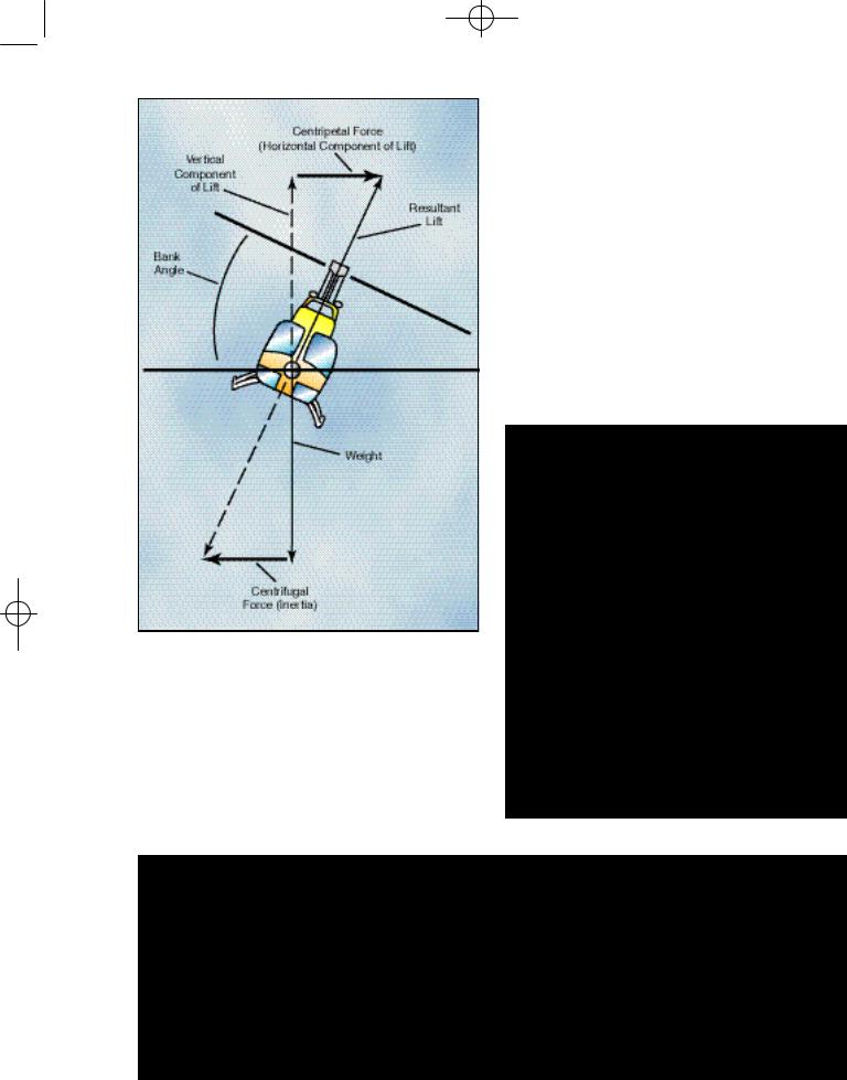
Figure 3-19. The horizontal component of lift accelerates the helicopter toward the center of the turn.
ping eliminates dissymmetry of lift, the front of the disc comes up, and the back of the disc goes down. This reorientation of the rotor disc changes the direction in which total rotor thrust acts so that the helicopter’s forward speed slows, but can be corrected with cyclic input.
SIDEWARD FLIGHT
In sideward flight, the tip-path plane is tilted in the direction that flight is desired. This tilts the total liftthrust vector sideward. In this case, the vertical or lift component is still straight up and weight straight down, but the horizontal or thrust component now acts sideward with drag acting to the opposite side. [Figure 3-17]
REARWARD FLIGHT
For rearward flight, the tip-path plane is tilted rearward, which, in turn, tilts the lift-thrust vector rearward. Drag now acts forward with the lift component straight up and weight straight down. [Figure 3-18]
Figure 3-21. Blade regions in vertical autorotation descent.
Figure 3-20. During an autorotation, the upward flow of relative wind permits the main rotor blades to rotate at their normal speed. In effect, the blades are “gliding” in their rotational plane.