

Rotorcraft Flying Handbook
.pdfCh 11.qxd 7/15/2003 9:14 AM Page 11-14
copters at airspeeds less than 30 knots. It is the result of the tail rotor not providing adequate thrust to maintain directional control, and is usually caused by either certain wind azimuths (directions) while hovering, or by an insufficient tail rotor thrust for a given power setting at higher altitudes.
For any given main rotor torque setting in perfectly steady air, there is an exact amount of tail rotor thrust required to prevent the helicopter from yawing either left or right. This is known as tail rotor trim thrust. In order to maintain a constant heading while hovering, you should maintain tail rotor thrust equal to trim thrust.
The required tail rotor thrust is modified by the effects of the wind. The wind can cause an uncommanded yaw by changing tail rotor effective thrust. Certain relative wind directions are more likely to cause tail rotor thrust variations than others. Flight and wind tunnel tests have identified three relative wind azimuth regions that can either singularly, or in combination, create an LTE conducive environment. These regions can overlap, and thrust variations may be more pronounced. Also, flight testing has determined that the tail rotor does not actually stall during the period. When operating in these areas at less than 30 knots, pilot workload increases dramatically.
MAIN ROTOR DISC INTERFERENCE (285-315°)
Refer to figure 11-10. Winds at velocities of 10 to 30 knots from the left front cause the main rotor vortex to be blown into the tail rotor by the relative wind. The effect of this main rotor disc vortex causes the tail rotor to operated in an extremely turbulent environment. During a right turn, the tail rotor experiences a reduction of thrust as it comes into the area of the main rotor disc vortex. The reduction in tail rotor thrust comes from the airflow changes experienced at the tail rotor as the main rotor disc vortex moves across the tail rotor disc. The effect of the main rotor disc vortex initially increases the angle of attack of the tail rotor blades, thus increasing tail rotor thrust. The increase in the angle of attack requires that right pedal pressure be added to reduce tail rotor thrust in order to maintain the same rate of turn. As the main rotor vortex passes the tail rotor, the tail rotor angle of attack is reduced. The reduction in the angle of attack causes a reduction in thrust and a right yaw acceleration begins. This acceleration can be surprising, since you were previously adding right pedal to maintain the right turn rate. This thrust reduction occurs suddenly, and if uncorrected, develops into an uncontrollable rapid rotation about the mast. When operating within
this region, be aware that the reduction in tail rotor thrust can happen quite suddenly, and be prepared to react quickly to counter this reduction with additional left pedal input.
Figure 11-10. Main rotor disc vortex interference.
WEATHERCOCK STABILITY (120-240°)
In this region, the helicopter attempts to weathervane its nose into the relative wind. [Figure 11-11] Unless a resisting pedal input is made, the helicopter starts a slow, uncommanded turn either to the right or left depending upon the wind direction. If the pilot allows a right yaw rate to develop and the tail of the helicopter moves into this region, the yaw rate can accelerate rapidly. In order to avoid the onset of LTE in this downwind condition, it is imperative to maintain positive control of the yaw rate and devote full attention to flying the helicopter.
Figure 11-11. Weathercock stability.
TAIL ROTOR VORTEX RING STATE (210-330°)
Winds within this region cause a tail rotor vortex ring state to develop. [Figure 11-12] The result is a non-uniform, unsteady flow into the tail rotor. The vortex ring state causes tail rotor thrust variations, which result in yaw deviations. The net effect of the unsteady flow is an oscillation of tail rotor thrust. Rapid and continuous pedal movements are necessary to compensate for the rapid changes in tail rotor thrust when hovering in a left crosswind. Maintaining a precise heading in this region is difficult, but this characteristic presents no significant problem unless corrective action is delayed. However, high pedal workload, lack of concentration and overcontrolling can all lead to LTE.
When the tail rotor thrust being generated is less than the thrust required, the helicopter yaws to the right. When hovering in left crosswinds, you must concentrated on smooth pedal coordination and not allow an uncontrolled right yaw to develop. If a right yaw rate is allowed to build, the helicopter can rotate into the wind azimuth region where weathercock stability then accelerates the right turn rate. Pilot workload during a tail rotor vortex ring state is high. Do not allow a right yaw rate to increase.
Figure 11-12. Tail rotor vortex ring state.
LTE AT ALTITUDE
At higher altitudes, where the air is thinner, tail rotor thrust and efficiency is reduced. When oper-

Ch 11.qxd 7/15/2003 9:14 AM Page 11-15
ating at high altitudes and high gross weights, especially while hovering, the tail rotor thrust may not be sufficient to maintain directional control and LTE can occur. In this case, the hovering ceiling is limited by tail rotor thrust and not necessarily power available. In these conditions gross weights need to be reduced and/or operations need to be limited to lower density altitudes.
REDUCING THE ONSET OF LTE
To help reduce the onset of loss of tail rotor effectiveness, there are some steps you can follow.
1.Maintain maximum power-on rotor r.p.m. If the main rotor r.p.m. is allowed to decrease, the antitorque thrust available is decreased proportionally.
and decrease rotor r.p.m. The decision to reduce collective must be based on your assessment of the altitude available for recovery.
If the rotation cannot be stopped and ground contact is imminent, an autorotation may be the best course of action. Maintain full left pedal until the rotation stops, then adjust to maintain heading.
MAIN DRIVE SHAFT FAILURE
The main drive shaft, located between the engine and the main rotor gearbox, transmits engine power to the main rotor gearbox. In some helicopters, particularly those with piston engines, a drive belt is used instead of a drive shaft. A failure of the drive shaft or belt has the same effect as an engine failure, because power is no longer provided to the main rotor, and an autorotation has to
2.Avoid tailwinds below an airspeed of 30 be initiated. There are a few differences,
knots. If loss of translational lift occurs, it results in an increased power demand and additional antitorque pressures.
3.Avoid out of ground effect (OGE) operations and high power demand situations below an airspeed of 30 knots.
4.Be especially aware of wind direction and velocity when hovering in winds of about 8-12 knots. There are no strong indicators that translational lift has been reduced. A loss of translational lift results in an unexpected high power demand and an increased antitorque requirement.
5.Be aware that if a considerable amount of left pedal is being maintained, a sufficient amount of left pedal may not be available to counteract an unanticipated right yaw.
6.Be alert to changing wind conditions, which may be experienced when flying along ridge lines and around buildings.
RECOVERY TECHNIQUE
If a sudden unanticipated right yaw occurs, the following recovery technique should be performed. Apply full left pedal while simultaneously moving cyclic control forward to increase speed. If altitude permits, reduce power. As recovery is effected, adjust controls for normal forward flight.
Collective pitch reduction aids in arresting the yaw rate but may cause an excessive rate of descent. Any large, rapid increase in collective to prevent ground or
however, that need to be taken into consideration. If the drive shaft or belt breaks, the lack of any load on the engine results in an overspeed. In this case, the throttle must be closed in order to prevent any further damage. In some helicopters, the tail rotor drive system continues to be powered by the engine even if the main drive shaft breaks. In this case, when the engine unloads, a tail rotor overspeed can result. If this happens, close the throttle immediately and enter an autorotation.
HYDRAULIC FAILURES
Most helicopters, other than smaller piston powered helicopters, incorporate the use of hydraulic actuators to overcome high control forces. A hydraulic system consists of actuators, also called servos, on each flight control; a pump, which is usually driven by the main rotor gearbox; and a reservoir to store the hydraulic fluid. A switch in the cockpit can turn the system off, although it is left on under normal conditions. A pressure indicator in the cockpit may be installed to monitor the system.
An impending hydraulic failure can be recognized by a grinding or howling noise from the pump or actuators, increased control forces and feedback, and limited control movement. The corrective action required is stated in detail in the appropriate rotorcraft flight manual. However, in most cases, airspeed needs to be reduced in order to reduce control forces. The hydraulic switch and circuit breaker should be checked and recycled. If hydraulic power is not restored, make a shallow approach to a running or roll-on landing.
This technique is used because it requires less

Ch 11.qxd 7/15/2003 9:14 AM Page 11-16
control force and pilot workload. Additionally, the hydraulic system should be disabled, by either pulling the circuit breaker and/or placing the switch in the off position. The reason for this is to prevent an inadvertent restoration of hydraulic power, which may lead to overcontrolling near the ground.
In those helicopters where the control forces are so high that they cannot be moved without hydraulic assistance, two or more independent hydraulic systems may be installed. Some helicopters use hydraulic accumulators to store pressure that can be used for a short time while in an emergency if the hydraulic pump fails. This gives you enough time to land the helicopter with normal control.
GOVERNOR FAILURE
Governors automatically adjust engine power to maintain rotor r.p.m. when the collective pitch is changed. If the governor fails, any change in collective pitch requires you to manually adjust the throttle to maintain correct r.p.m. In the event of a high side governor failure, the engine and rotor r.p.m. try to increase above the normal range. If the r.p.m. cannot be reduced and controlled with the throttle, close the throttle and enter an autorotation. If the governor fails on the low side, normal r.p.m. may not be attainable, even if the throttle is manually controlled. In this case, the collective has to be lowered to maintain r.p.m. A running or roll-on landing may be performed if the engine can maintain sufficient rotor r.p.m. If there is insufficient power, enter an autorotation.
ABNORMAL VIBRATIONS
With the many rotating parts found in helicopters, some vibration is inherent. You need to understand the cause and effect of helicopter vibrations because abnormal vibrations cause premature component wear and may even result in structural failure. With experience, you learn what vibrations are normal versus those that are abnormal and can then decide whether continued flight is safe or not. Helicopter vibrations are categorized into low, medium, or high frequency.
LOW FREQUENCY VIBRATIONS
Low frequency vibrations (100-500 cycles per minute) usually originate from the main rotor system. The vibration may be felt through the controls, the airframe, or a combination of both. Furthermore, the vibration may have a definite direction of push or thrust. It may be vertical, lateral, horizontal, or even a combination. Normally, the direction of the vibration can be determined by
concentrating on the feel of the vibration, which may push you up and down, backwards and forwards, or from side to side. The direction of the vibration and whether it is felt in the controls or the airframe is an important means for the mechanic to troubleshoot the source. Some possible causes could be that the main rotor blades are out of track or balance, damaged blades, worn bearings, dampers out of adjustment, or worn parts.
MEDIUM AND HIGH FREQUENCY VIBRATIONS Medium frequency vibrations (1,000 - 2,000 cycles per minute) and high frequency vibrations (2,000 cycles per minute or higher) are normally associated with out-of-balance components that rotate at a high r.p.m., such as the tail rotor, engine, cooling fans, and components of the drive train, including transmissions, drive shafts, bearings, pulleys, and belts. Most tail rotor vibrations can be felt through the tail rotor pedals as long as there are no hydraulic actuators, which usually dampen out the vibration. Any imbalance in the tail rotor system is very harmful, as it can cause cracks to develop and rivets to work loose. Piston engines usually produce a normal amount of high frequency vibration, which is aggravated by engine malfunctions such as spark plug fouling, incorrect magneto timing, carburetor icing and/or incorrect fuel/air mixture. Vibrations in turbine engines are often difficult to detect as these engines operate at a very high r.p.m.
TRACKING AND BALANCE
Modern equipment used for tracking and balancing the main and tail rotor blades can also be used to detect other vibrations in the helicopter. These systems use accelerometers mounted around the helicopter to detect the direction, frequency, and intensity of the vibration. The built-in software can then analyze the information, pinpoint the origin of the vibration, and suggest the corrective action.
FLIGHT DIVERSION
There will probably come a time in your flight career when you will not be able to make it to your destination. This can be the result of unpredictable weather conditions, a system malfunction, or poor preflight planning. In any case, you will need to be able to safely and efficiently divert to an alternate destination. Before any crosscountry flight, check the charts for airports or suitable landing areas along or near your route of flight. Also, check for navaids that can be used during a diversion.

CH 12.qxd 7/15/2003 9:14 AM Page 12-1
Attitude instrument flying in helicopters is essentially visual flying with the flight instruments substituted for the various reference points on the helicopter and the natural horizon. Control changes, required to produce a given attitude by reference to instruments, are identical to those used in helicopter VFR flight, and your thought processes are the same. Basic instrument training is intended as a building block towards attaining an instrument rating. It will also enable you to do a 180° turn in case of inadvertent incursion into instrument meteorological conditions (IMC).
FLIGHT INSTRUMENTS
When flying a helicopter with reference to the flight instruments, proper instrument interpretation is the basis for aircraft control. Your skill, in part, depends on your understanding of how a particular instrument or system functions, including its indications and limitations. With this knowledge, you can quickly determine what an instrument is telling you and translate that information into a control response.
PITOT-STATIC INSTRUMENTS
The pitot-static instruments, which include the airspeed indicator, altimeter, and vertical speed indicator, operate on the principle of differential air pressure. Pitot pressure, also called impact, ram, or dynamic pressure, is directed only to the airspeed indicator, while static pressure, or ambient pressure, is directed to all three instruments. An alternate static source may be included allowing you to select an alternate source of ambient pressure in the event the main port becomes blocked. [Figure 12-1]
AIRSPEED INDICATOR
The airspeed indicator displays the speed of the helicopter through the air by comparing ram air pressure from the pitot tube with static air pressure from the static port—the greater the differential, the greater the speed. The instrument displays the result of this pressure differential as indicated airspeed (IAS). Manufacturers use this speed as the basis for determining helicopter performance, and it may be displayed in knots, miles
Figure 12-1. Ram air pressure is supplied only to the airspeed indicator, while static pressure is used by all three instruments. Electrical heating elements may be installed to prevent ice from forming on the pitot tube. A drain opening to remove moisture is normally included.
per hour, or both. [Figure 12-2] When an indicated airspeed is given for a particular situation, you normally use that speed without making a correction for altitude or temperature. The reason no correction is needed is that an airspeed indicator and air-
Figure 12-2. Ram air pressure from the pitot tube is directed to a diaphragm inside the airspeed indicator. The airtight case is vented to the static port. As the diaphragm expands or contracts, a mechanical linkage moves the needle on the face of the indicator.
craft performance are affected equally by changes in air density. An indicated airspeed always yields the same performance because the indicator has, in fact, compensated for the change in the environment.

CH 12.qxd 7/15/2003 9:14 AM Page 12-2
INSTRUMENT CHECK—During the preflight, ensure that the pitot tube, drain hole, and static ports are unobstructed. Before liftoff, make sure the airspeed indicator is reading zero. If there is a strong wind blowing directly at the helicopter, the airspeed indicator may read higher than zero, depending on the wind speed and direction. As you begin your takeoff, make sure the airspeed indicator is increasing at an appropriate rate. Keep in mind, however, that the airspeed indication might be
recently you have set the altimeter. The best way to minimize altimeter errors is to update the altimeter setting frequently. In most cases, use the current altimeter setting of the nearest reporting station along your route of flight per regulatory requirements.
Figure 12-3. The main component of the altimeter is a stack of sealed aneroid wafers. They expand and contract as atmospheric pressure from the static source changes. The mechanical linkage translates these changes into pointer movements on the indicator.
unreliable below a certain airspeed due to rotor downwash.
ALTIMETER
The altimeter displays altitude in feet by sensing pressure changes in the atmosphere. There is an adjustable barometric scale to compensate for changes in atmospheric pressure. [Figure 12-3]
The basis for altimeter calibration is the International Standard Atmosphere (ISA), where pressure, temperature, and lapse rates have standard values. However, actual atmospheric conditions seldom match the standard values. In addition, local pressure readings within a given area normally change over a period of time, and pressure frequently changes as you fly from one area to another. As a result, altimeter indications are subject to errors, the extent of which depends on how much the pressure, temperature, and lapse rates deviate from standard, as well as how
Figure 12-4. Although the sealed case and diaphragm are both connected to the static port, the air inside the case is restricted through a calibrated leak. When the pressures are equal, the needle reads zero. As you climb or descend, the pressure inside the diaphragm instantly changes, and the needle registers a change in vertical direction. When the pressure differential stabilizes at a definite ratio, the needle registers the rate of altitude change.
INSTRUMENT CHECK—During the preflight, ensure that the static ports are unobstructed. Before liftoff, set the altimeter to the current setting. If the altimeter indicates within 75 feet of the actual elevation, the altimeter is generally considered acceptable for use.
VERTICAL SPEED INDICATOR
The vertical speed indicator (VSI) displays the rate of climb or descent in feet per minute (f.p.m.) by measuring how fast the ambient air pressure increases or decreases as the helicopter changes altitude. Since the VSI measures only the rate at which air pressure changes, air temperature has no effect on this instrument. [Figure 12-4]
There is a lag associated with the reading on the VSI, and it may take a few seconds to stabilize when showing rate of climb or descent. Rough control technique and turbulence can further extend the lag period and cause erratic and unstable rate indications. Some aircraft are equipped with an instantaneous vertical speed indicator (IVSI), which incorporates accelerometers to compensate for the lag found in the typical VSI.

CH 12.qxd 7/15/2003 9:14 AM Page 12-3
INSTRUMENT CHECK—During the preflight, ensure that the static ports are unobstructed. Check to see that the VSI is indicating zero before lift-off. During takeoff, check for a positive rate of climb indication.
SYSTEM ERRORS
The pitot-static system and associated instruments are usually very reliable. Errors are generally caused when the pitot or static openings are blocked. This may be caused by dirt, ice formation, or insects. Check the pitot and static openings for obstructions during the preflight. It is also advisable to place covers on the pitot and static ports when the helicopter is parked on the ground.
The airspeed indicator is the only instrument affected by a blocked pitot tube. The system can become clogged in two ways. If the ram air inlet is clogged, but the drain hole remains open, the airspeed indicator registers zero, regardless of airspeed. If both the ram air inlet and the drain hole become blocked, pressure in the line is trapped, and the airspeed indicator reacts like an altimeter, showing an increase in airspeed with an increase in altitude, and a decrease in speed as altitude decreases. This occurs as long as the static port remains unobstructed.
If the static port alone becomes blocked, the airspeed indicator continues to function, but with incorrect readings. When you are operating above the altitude where the static port became clogged, the airspeed indicator reads lower than it should. Conversely, when operating below that altitude, the indicator reads higher than the correct value. The amount of error is proportional to the distance from the altitude where the static system became blocked. The greater the difference, the greater the error. With a blocked static system, the altimeter freezes at the last altitude and the VSI freezes at zero. Both instruments are then unusable.
Some helicopters are equipped with an alternate static source, which may be selected in the event that the main static system becomes blocked. The alternate source generally vents into the cabin, where air pressures are slightly different than outside pressures, so the airspeed and altimeter usually read higher than normal. Correction charts may be supplied in the flight manual.
GYROSCOPIC INSTRUMENTS
The three gyroscopic instruments that are required for instrument flight are the attitude indicator, heading indicator, and turn indicator. When installed in helicopters, these instruments are usually electrically powered.
Gyros are affected by two principles—rigidity in space and precession. Rigidity in space means that once a gyro is spinning, it tends to remain in a fixed position and resists external forces applied to it. This principle allows a gyro to be used to measure changes in attitude or direction.
Figure 12-5. The gyro in the attitude indicator spins in the horizontal plane. Two mountings, or gimbals, are used so that both pitch and roll can be sensed simultaneously. Due to rigidity in space, the gyro remains in a fixed position relative to the horizon as the case and helicopter rotate around it.
Precession is the tilting or turning of a gyro in response to pressure. The reaction to this pressure does not occur at the point where it was applied; rather, it occurs at a point that is 90° later in the direction of rotation from where the pressure was applied. This principle allows the gyro to determine
Figure 12-6. A heading indicator displays headings based on a 360° azimuth, with the final zero omitted. For example, a 6 represents 060°, while a 21 indicates 210°. The adjustment knob is used to align the heading indicator with the magnetic compass.

CH 12.qxd 7/15/2003 9:14 AM Page 12-4
a rate of turn by sensing the amount of pressure created by a change in direction. Precession can also create some minor errors in some instruments.
ATTITUDE INDICATOR
The attitude indicator provides a substitute for the natural horizon. It is the only instrument that provides an immediate and direct indication of the helicopter’s pitch and bank attitude. Since most attitude indicators installed in helicopters are electrically powered, there may be a separate power switch, as well as a warning flag within the instrument, that indicates a loss of power. A caging or “quick erect” knob may be included, so you can stabilize the spin axis if the gyro has tumbled. [Figure 12-5]
HEADING INDICATOR
The heading indicator, which is sometimes referred to as a directional gyro (DG), senses movement around the vertical axis and provides a more accurate heading reference compared to a magnetic compass, which has a number of turning errors. [Figure 12-6].
Due to internal friction within the gyroscope, precession is common in heading indicators. Precession causes the selected heading to drift from the set value. Some heading indicators receive a magnetic north reference from a remote source and generally need no adjustment.
Figure 12-7. The gyros in both the turn-and-slip indicator and the turn coordinator are mounted so that they rotate in a vertical plane. The gimbal in the turn coordinator is set at an angle, or canted, which means precession allows the gyro to sense both rate of roll and rate of turn. The gimbal in the turn-and-slip indicator is horizontal. In this case, precession allows the gyro to sense only rate of turn. When the needle or miniature aircraft is aligned with the turn index, you are in a standard-rate turn.
Heading indicators that do not have this automatic north-seeking capability are often called “free” gyros, and require that you periodically adjust them. You should align the heading indicator with the magnetic compass before flight and check it at 15-minute intervals during flight. When you do an in-flight alignment, be certain you are in straight-
Figure 12-8. In a coordinated turn (instrument 1), the ball is centered. In a skid (instrument 2), the rate of turn is too great for the angle of bank, and the ball moves to the outside of the turn. Conversely, in a slip (instrument 3), the rate of turn is too small for the angle of bank, and the ball moves to the inside of the turn.
and-level, unaccelerated flight, with the magnetic compass showing a steady indication.
TURN INDICATORS
Turn indicators show the direction and the rate of turn. A standard rate turn is 3° per second, and at this rate you will complete a 360° turn in two minutes. A half-standard rate turn is 1.5° per second. Two types of indicators are used to display this information. The turn-and-slip indicator uses a needle to indicate direction and turn rate. When the needle is aligned with the white markings, called the turn index, you are in a standard rate turn. A half-standard rate turn is indicated when the needle is halfway between the indexes. The turn-and-slip indicator does not indicate roll rate. The turn coordinator is similar to the turn-and-slip indicator, but the gyro is canted, which allows it to sense roll rate in addition to rate of turn. The turn coordinator uses a miniature aircraft to indicate direction, as well as the turn and roll rate. [Figure 12-7]
Another part of both the turn coordinator and the turn-and-slip indicator is the inclinometer. The position of the ball defines whether the turn is coordinated or not. The helicopter is either slipping or skidding anytime the ball is not centered, and usually requires an adjustment of the anti - torque pedals or angle of bank to correct it. [Figure 12-8]
INSTRUMENT CHECK—During your preflight, check

CH 12.qxd 7/15/2003 9:14 AM Page 12-5
no air bubbles. The ball should also be resting at its lowest point. Since almost all gyroscopic instruments installed in a helicopter are electrically driven, check to see that the power indicators are displaying off indications. Turn the master switch on and listen to the gyros spool up. There should be no abnormal sounds, such as a grinding sound, and the power out indicator flags should not be displayed. After engine start and before liftoff, set the direction indicator to the magnetic compass. During hover turns, check the heading
Figure 12-9. Variation at point A in the western United States is 17°. Since the magnetic north pole is located to the east of the true north pole in relation to this point, the variation is easterly. When the magnetic pole falls to the west of the true north pole, variation is westerly.
indicator for proper operation and ensure that it has not precessed significantly. The turn indicator should also indicate a turn in the correct direction. During takeoff, check the attitude indicator for proper indication and recheck it during the first turn.
MAGNETIC COMPASS
In some helicopters, the magnetic compass is the only direction seeking instrument. Although the compass appears to move, it is actually mounted in such a way that the helicopter turns about the compass card as the card maintains its alignment with magnetic north.
COMPASS ERRORS
The magnetic compass can only give you reliable directional information if you understand its limitations and inherent errors. These include magnetic variation, compass deviation, and magnetic dip.
MAGNETIC VARIATION
When you fly under visual flight rules, you ordinarily navigate by referring to charts, which are
oriented to true north. Because the aircraft compass is oriented to magnetic north, you must make allowances for the difference between these poles in order to navigate properly. You do this by applying a correction called variation to convert a true direction to a magnet direction. Variation at a given point is the angular difference between the true and magnetic poles. The amount of variation depends on where you are located on the earth’s surface. Isogonic lines connect points where the variation is equal, while the agonic line defines the points where the variation is zero. [Figure 12-9]
COMPASS DEVIATION
Besides the magnetic fields generated by the earth, other magnetic fields are produced by metal and electrical accessories within the helicopter. These magnetic fields distort the earth’s magnet force and cause the compass to swing away from the correct heading. Manufacturers often install compensating magnets within the compass housing to reduce the effects of deviation. These magnets are usually adjusted while the engine is running and all electrical equipment is operating. Deviation error, however, cannot be completely eliminated; therefore, a compass correction card is mounted near the compass. The compass correction card corrects for deviation that occurs from one heading to the next as the lines of force interact at different angles.
MAGNETIC DIP
Magnetic dip is the result of the vertical component of the earth’s magnetic field. This dip is virtually non-existent at the magnetic equator, since the lines of force are parallel to the earth’s surface and the vertical component is minimal. As you move a compass toward the poles, the vertical component increases, and magnetic dip becomes more apparent at these higher latitudes. Magnetic dip is responsible for compass errors during acceleration, deceleration, and turns.
Acceleration and deceleration errors are fluctuations in the compass during changes in speed. In the northern hemisphere, the compass swings toward the north during acceleration and toward the south during deceleration. When the speed stabilizes, the compass returns to an accurate indication. This error is most pronounced when you are flying on a heading of east or west, and decreases gradually as you fly closer to a north or south heading. The error does not occur when you are flying directly north or south. The memory aid, ANDS (Accelerate North, Decelerate
South) may help you recall this error. In the
CH 12.qxd 7/15/2003 9:14 AM Page 12-6
southern hemisphere, this error occurs in the opposite direction.
Turning errors are most apparent when you are turning to or from a heading of north or south. This error increases as you near the poles as magnetic dip becomes more apparent. There is no turning error when flying near the magnetic equator. In the northern hemisphere, when you make a turn from a northerly heading, the compass gives an initial indication of a turn in the opposite direction. It then begins to show the turn in the proper direction, but lags behind the actual heading. The amount of lag decreases as the turn continues, then disappears as the helicopter reaches a heading of east or west. When you make a turn from a southerly heading, the compass gives an indication of a turn in the correct direction, but leads the actual heading. This error also disappears as the helicopter approaches an east or west heading.
INSTRUMENT CHECK—Prior to flight, make sure that the compass is full of fluid. During hover turns, the compass should swing freely and indicate known headings. Since that magnetic compass is required for all flight operations, the aircraft should never be flown with a faulty compass.
INSTRUMENT FLIGHT
To achieve smooth, positive control of the helicopter during instrument flight, you need to develop three fundamental skills. They are instru-
ment cross-check, instrument interpretation, and aircraft control.
INSTRUMENT CROSS-CHECK
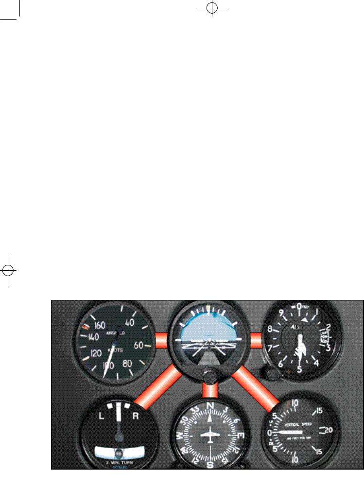
Cross-checking, sometimes referred to as scanning, is the continuous and logical observation of instruments for attitude and performance information. In attitude instrument flying, an attitude is maintained by reference to the instruments, which produces the desired result in performance. Due to human error, instrument error, and helicopter performance differences in various atmospheric and loading conditions, it is difficult to establish an attitude and have performance remain constant for a long period of time. These variables make it necessary for you to constantly check the instruments and make appropriate changes in the helicopter’s attitude. The actual technique may vary depending on what instruments are installed and where they are installed, as well as your experience and proficiency level. For this discussion, we will concentrate on the six basic flight instruments discussed earlier. [Figure 12-10]
At first, you may have a tendency to cross-check rapidly, looking directly at the instruments without knowing exactly what information you are seeking. However, with familiarity and practice, the instrument cross-check reveals definite trends during specific flight conditions. These trends help you control the
Figure 12-10. In most situations, the cross-check pattern includes the attitude indicator between the cross-check of each of the other instruments. A typical cross-check might progress as follows: attitude indicator, altimeter, attitude indicator, VSI, attitude indicator, heading indicator, attitude indicator, and so on.

CH 12.qxd 7/15/2003 9:14 AM Page 12-7
helicopter as it makes a transition from one flight condition to another.
If you apply your full concentration to a single instrument, you will encounter a problem called “fixation.” This results from a natural human inclination to observe a specific instrument carefully and accurately, often to the exclusion of other instruments. Fixation on a single instrument usually results in poor control. For example, while performing a turn, you may have a tendency to watch only the turn-and-slip indicator instead of including other instruments in your cross-check. This fixation on the turn-and-slip indicator often leads to a loss of altitude through poor pitch and bank control. You should look at each instrument only long enough to understand the information it presents, then continue on to the next one. Similarly, you may find yourself placing too much “emphasis” on a single instrument, instead of relying on a combination of instruments necessary for helicopter performance information. This differs from fixation in that you are using other instruments, but are giving too much attention to a particular one.
During performance of a maneuver, you may sometimes fail to anticipate significant instrument indications following attitude changes. For example, during leveloff from a climb or descent, you may concentrate on pitch control, while forgetting about heading or roll information. This error, called “omission,” results in erratic control of heading and bank.
In spite of these common errors, most pilots can adapt well to flight by instrument reference after instruction and practice. You may find that you can control the helicopter more easily and precisely by instruments.
INSTRUMENT INTERPRETATION
The flight instruments together give a picture of what is going on. No one instrument is more important than the next; however, during certain maneuvers or conditions, those instruments that provide the most pertinent and useful information are termed primary instruments. Those which back up and supplement the primary instruments are termed supporting instruments. For example, since the attitude indicator is the only instrument that provides instant and direct aircraft attitude information, it should be considered primary during any change in pitch or bank attitude. After the new attitude is established, other instruments become primary, and the attitude indicator usually becomes the supporting instrument.
AIRCRAFT CONTROL
Controlling the helicopter is the result of accurately interpreting the flight instruments and translating these readings into correct control responses. Aircraft control involves adjustment to pitch, bank, power, and trim in order to achieve a desired flight path.
Figure 12-11. The flight instruments for pitch control are the airspeed indicator, attitude indicator, altimeter, and vertical speed indicator.