

Учебное пособие 2210
.pdfIssue № 4 (36), 2017 |
ISSN 2542-0526 |
Fig. 10 b. Deformation of building in both directions for Trilinear Concrete Model
Fig. 10 c. Deformation of building in both directions for Chang –Mander Nonlinear Concrete Model
Fig. 10 d. Deformation of building in both directions for Kappos-Konstantinidis Nonlinear Concrete Model
The comparison of peak displacement amounts obtained for four different concrete models used is shown at Table 1.
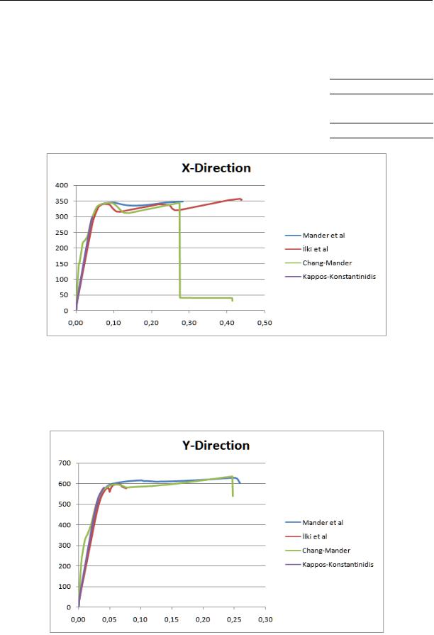
The comparison of static pushover analysis curves for X direction for four different concrete models used in the study is given all Fig. 11.
101
Russian Journal of Building Construction and Architecture
Table 1
Comparision of peak displacement for concrete models
Model |
|
Direction |
|
X (cm) |
|
Y (cm) |
|
|
|
||
|
|
|
|
Mander et al (1988) |
25.90 |
|
28,80 |
Ilki et al (2003) |
24.70 |
|
41.40 |
Chang and Mander (1994) |
4.10 |
|
45.60 |
|
|
|
|
Kappos and Konstantinidis (1999) |
7.60 |
|
43.80 |
Fig. 11. Comparision of pushover curves for X direction
The comparison of static pushover analysis curves for Y direction for four different concrete models used in the study is given at Fig. 12.
Fig. 12. Comparision of pushover curves for X direction
102
Issue № 4 (36), 2017 |
ISSN 2542-0526 |
Conclusions
A civil engineer should reach an economic resolution under adequate safety while designing a structure. For this, three principal elements; material, dimensions and load are needed. A civil engineer takes the numerical values for the materials to be used in structures from stress-strain relationship while designing. As these features of materials are based up several factors, stress-strain relationship is idealized, establishing mathematical models. There has been a number of models regarding concrete materials which is the weakest link of concrete structures. The analysis is simplified by these models and the margin of error is reduced as possible.
By this study, information on concrete material constituting concrete structures and the models regarding them is given and these models’ usability on structure design and the differences between them are aimed to be revealed.
In this study, a static pushover analysis for four different concrete models is conducted in a structure selected for this selection. For each model, the peak strain in X and Y axes are calculated. Furthermore, for each model, static pushover values of X and Y axes are measured and comparisons are made.
The peak strain values calculated in X axis are very close to each other in Mander et al. (1988) and İlki et al. (2003) models, while very different from the other two models. The calculations of those two models are close to each other as well. In the Y axis; the peak strain values in Ilki et al, Chang and Mander (1994) and Kappos-Konstantinidis (1999) models are very close to each other. In the Y axis, the value measured in Mander (1988) model is smaller than others.
The static pushover analysis results made for different concrete models and in different axes are found to be compatible with each other. The results of the concrete models used are not different from each other significantly. It has been found out that all of these four models can be used as a concrete model in structure design.
References
1.Işık E., Kaya C. and Tapancı T. Effects of Material Strength on Structural Performance for the Irregularity Structur. Int. Journal of Novel Research in Civil Structural and Earth Sciences, vol. 2, no.2, 2015, pp. 23––28.
2.Mander J. B., Priestley M. J. N., Park R. Theoretical Stress-Strain Model for Confined Concrete. Journal of Structural Engineering, ASCE, 1998, vol. 114, no. 8, pp. 1804––1825.
103

Russian Journal of Building Construction and Architecture
3.İlki A., Fukuta T. and Özdemir P. Sargılı Beton Davranışı ve Üç Doğrudan Oluşan Gerilme –– Şekil Değiştirme Modeli. IMO Teknik Dergi, Yazı No: 190, 2003, pp. 2853––2871.
4.Chang G. A. and Mander J. B. Seismic Energy Based Fatigue Damage Analysis of Bridge Columns: Part 1 –– Evaluation of Seismic Capacity. NCEER Technical Report No. NCEER-94-0006, State University of New York, Buffalo, N. Y, 1994.
5.Kappos A. and Konstantinidis D. Statistical Analysis of Confined High Strength Concrete. Materials and Structures, 1999, vol. 32, pp. 734––748.
6.Türk K. Betonarme I Ders Notları, Harran Üniversitesi, Şanlıurfa, Turkey, 2011.
7.Çağlar N. Betonarme. Available at: http://slideplayer.biz.tr/slide/2798854/ (accessed 15.03.2016).
8.Celep Z. and Kumbasar N. Deprem Mühendisliğine Giriş ve Depreme Dayanıklı Yapı Tasarımı, Beta Dağıtım. 742 p.
9.Wu H. Constitutive Model of Concrete Confined by Advanced Fiber Composite Materials and Applications in Seismic Retrofitting, 2007, ProQuest.
10.Antoniou S. and Pinho R. Seismostruct–Seismic Analysis program by Seismosoft, Technical manual and User manual, 2003.
11.Code, Turkish Earthquake. Specification for Structures to be Built in Disaster Areas” Ministry of Public Works and Settlement Government of Republic of Turkey, 2007. 168 p.
12.Özmen H. B. and İnel M., Betonarme Yapılarda Malzeme Dayanımı ve Detaylandırma Özelliklerinin Sismik Hasar Üzerine Etkisinin Değerlendirilmesi. 1. Türkiye Deprem Mühendisliği ve Sismoloji Konferansı, 11––14 Ekim 2011, Ankara, Turkey.
13.Rediiar M. K. M. Stress-Strain Model of Unconfined and Confined Concrete and Stress-Block Parameters. Diss. Texas A&M University, 2009.
14.Nagashima T., Sugano S., Kimura H. and Ichikawa A. Monotonic Axial Compression Test on Ultra-High-
Strength Concrete Tied Columns. In 10th World Conference on Earthquake Engineering, 1992, no. 5, pp. 2983––2988.
15.Sheikh S. A. and Uzumeri S. M. Analytical Model for Concrete Confinement in Tied Columns. Journal of the Structural Division, 1982, vol. 108, no. 12, pp. 2703––2722.
16.Aydınoğlu M. N. A Response Spectrum-Based Nonlinear Assessment Tool For Practice: Incremental Response Spectrum Analysis (IRSA), ISET Journal of Earthquake Technology, 2007, vol. 44, no. 1, pp. 169––192.
17.Doran B., Akbaş B., Sayım İ., Fahjan Y. and Alacalı S. N. Uzun Periyotlu Bir Yapıda Yapısal Sağlık İzlemesi ve Deprem Performansının Belirlenmesi. 1. Türkiye Deprem Mühendisliği ve Sismoloji Konferansı, 11––14 Ekim, ODTÜ, Ankara, 2011.
18.Kutanis M. and Boru O. E. The Need For Upgrading The Seismic Performance Objectives. Earthquakes and Structures, 2014, vol. 7, no. 4, pp. 401––414.
19.Ilki A. and Celep Z. Betonarme Yapıların Deprem Güvenliği. 1. Türkiye Deprem Mühendisliği ve Sismoloji Konferansı, Ankara, Turkey, October, 2011.
20.Özer E. Performansa Dayalı Tasarım ve Değerlendirme, ITU, Lectures Notes, 2007.
21.Fajfar P. Capacity Spectrum Method Based on Inelastic Demand Spectra. Earthquake Engineering and Structural Dynamics, 1999, vol. 28, no. 9, pp. 979––993.
104
Issue № 4 (36), 2017 |
ISSN 2542-0526 |
22.Işık E. and Kutanis M. Performance Based Assessment for Existing Residential Buildings in Lake Van Basin and Seismicity of the Region. Earthquakes and Structures, 2015, vol. 9, no. 4, pp. 893––910.
23.Chopra A. K. and Goel R. K. A Modal Pushover Analysis Procedure for Estimating Seismic Demands for Buildings. Earthquake Engineering and Structural Dynamics, 2002, vol. 31, no. 3, pp. 561––582.
24.Jianmeng M., Changhai Z. and Lili X. An Improved Modal Pushover Analysis Procedure for Estimating Seismic Demands Of Structures. Earthquake Engineering and Engineering Vibration, 2008, vol. 7, no. 1, pp. 25––31.
25.Freeman S. A. The Capacity Spectrum Method as a Tool for Seismic Design. In Proceedings of the 11th European Conference on Earthquake Engineering, 1998, pp. 6––11.
105

Russian Journal of Building Construction and Architecture
TECHNOLOGY AND ORGANIZATION OF CONSTRUCTION
UDC 624
IfeOlorun Olofin, Prof Ronggui Liu
STRUCTURAL OPTIMIZATION OF BEIJING GYMNASIUM SUSPEN-DOME WITH CARBON FIBRE REINFORCED POLYMER (CFRP) CABLE
Department of Civil Engineering, Jiangsu University
China, tel.: +86 18652726384, e-mail: epher2002@yahoo.com
Statement of the problem. A study on the structural behavior of carbon fibre reinforced polymer cable as a constitute material for the tensegrity system for Beijing gymnasium suspen dome compared with results of studies on of steel as the constitute material for the Beijing gymnasium structure is presented.
Results. Non linear software known as ANSYS was adopted for the analysis in this study. Based on the results of the analyses, the structural behavior of the carbon fibre reinforced polymer tensegrity system was compared with that of steel tensegrity system for the Beijing gymnasium suspen dome reported from other studies, taking into account the internal forces, displacement and frequency.
Conclusions. The comparison of these results indicates the efficiency of CFRP tensegrity system for the suspen dome, over that of steel tensegrity system.
Keywords:Suspen dome; CFRP tensegrity system, Steel tensegrity system, Finite element model, Static, Modal.
Introduction
The evolution of long span structures has made engineers to search for more reliable and dependable materials for such structure. Suspen dome which falls in such category has evolved tremendously over the past few years in roof design. The tensegrity system which makes up a part of the suspen dome is one of the most promising solutions for self equilibrium. However, the need to improve such system is required in order to be more dependable and controllable. The tensegrity system was developed by Fuller (Fu, 2005), (Wojciech, 2015) and the idea to incorporate the system into a single layer reticulated dome was created by Prof. Kawaguchi
© IfeOlorun Olofin, Prof Ronggui Liu, 2017
106
Issue № 4 (36), 2017 |
ISSN 2542-0526 |
and his team to form a system called suspen dome (Subramanian, 2006)which is attractive due to its structural properties. The construction of the structure includes Fureai dome and Hikarigaoka dome in Japan, Kiewitt suspen dome in Tianjin, Olympics badminton gymnasium suspen dome in Beijing, China, are few examples.
Cables are one of the main parts of a tensegrity system of a suspen dome; the choice of cables types depends mainly on the mechanical properties, structural properties and economical criteria. The evolution of Carbon fiber-reinforced polymer (CFRP) has impacted in the application of civil engineering structures due to its great strength, flexibility, light weight, fatigue and resistance to corrosion. However, its disadvantages include high cost, unfamiliarity with contractors, ductility, sensitivity to impact damage and difficulty in connections, even though CFRP cables are higher in some qualities compared to steel cables such as in some mechanical aspects; namely, relaxation and creep (Xu et al, 2015).
The stated reasons have made CFRP cables attain heights for its use in long span structures such as bridges. In order to extend the lifespan of a suspen dome, which is also a long span structure, a new material has to be introduced, the structural behavior of which would differ significantly compared to steel cable.
Static and dynamic research both on numerical and experimental results can be found in literature based on the application of steel material for suspen and even construction (Kitipornchai et al, 2005), (Wenjiang et al, 2003), (Behnam et al, 2012); no literature results are found on the application of carbon fibre reinforced polymer cables where such structure has been addressed. With the current tremendous studies involving carbon fibre by researchers, it is believed that optimizing the structure with carbon fibre material can lead to solutions where members can exceed their capabilities. In fact, the instability of a suspen dome can disappear because of the presence of carbon fibre reinforced polymer cables.
The analysis of the prototype suspen dome was through a non-linear software known as ANSYS (ANSYS,2008). Based on the analysis, the structural behavior of the CFRP tensegrity system for the prototype is summarized. A comparison between the literature results by Zhang et al [9] on Beijing Olympic badminton suspen dome with steel tensegrity and the CRFP tensegrity system proposedbythe authors of this studyis madeto validate the use of CFRP cables.
TheoriticalBackground
This section introduces the finite element formation for static and modal analysis. Static analysis predicts the structures deformation whereas the modal analysis predicts the most reliable design against vibration.
107

Russian Journal of Building Construction and Architecture
An overview on Static Analysis |
|
The fundamental equation for static analysis is given as: |
|
[K]{U} = –{P} + {R}, |
(1) |
where [K]= total stiffness; {U}= displacement vector of the node;{P}=load vector; {R}= residual force.
Investigating the static behavior of the system is very vital; this is attained by analyzing the force and deformation in the structure.
Incorporating Newton Raphson approach in solving the equation is given as |
|
|||||||
|
[K]{∆ U}={∆P}, |
|
|
|
(2) |
|||
where [K] = stiffness matrix; {∆U}= displacement increment; {∆P}= Load imbalance. |
||||||||
An overview on Modal Analysis |
|
|
|
|
|
|
|
|
The modal analysis can be expressed in matrix form as: |
|
|
|
|
|
|||
|
+ |
|
+ |
= |
, |
|
(3) |
|
where [M] = mass matrix; [C] = damping matrix; [K] = stiffness matrix; |
|
= displacement |
||||||
vector of each node; |
= velocity vector of each node; |
= acceleration vector of each |
||||||
node, and {F}= force vector |
|
|
|
|
|
|
|
|
Ignoring resistance, a dynamic equilibrium equation can be obtained as: |
|
|
||||||
|
|
|
+ |
= 0 |
|
|
(4) |
|
Assume a harmonic motion |
|
|
|
|
|
|
|
|
|
{u} { i }sin( it i ),i 1,2,....n |
|
(5) |
|||||
|
.. |
{ }sin( t |
) |
|
|
|
||
|
{u} 2 |
|
|
(6) |
||||
|
i |
i |
i |
i |
|
|
|
|
Where |
|
|
|
|
|
|
|
|
n = number of degree of freedom, { }=eigenvectors, |
2 = eigenvalues, |
i |
= the phase angle |
|||||
|
i |
|
|
|
i |
|
|
|
for i mode of vibration.
The eigenvectors and eigenvalues represent the mode shapes and the square of the natural circular frequency.
.. |
|
|
Substituting {u}and {u} in the governing equation gives |
|
|
|
= 0. |
(7) |
Equality is given if { i }=0. |
|
|
Where = natural frequency of the system, and |
= vibration modals of the structure. |
|
108

Issue № 4 (36), 2017 |
ISSN 2542-0526 |
Layout and material used for Beijing Olympic Suspen dome
Based on appropriate simplification, the physical dimensions of Beijing Olympic Badminton Gymnasium suspen dome are given as follows (Ge et al, 2007a), Ge et al, 2007b), (Liu, 2010), the span the model is 93m and 8m high, fixed and hinged as shown in Fig. 1.
a) single-layer reticulated shell |
b) Tensegrity system |
c) Suspen dome |
Fig. 1. Suspen dome model
The single layer reticulated shell is a Φ219x10 circular steel pipe with Q345 steel circular tube of Φ 168 x 8 for strut and a yielding strength of 345N/mm2.The permanent and live load of the roof are 0.85kN/m2 and 0.5kN/m2 respectively. Based on static equivalent principle, the uniformly distributed load is equivalent to a vertical concentrated load on each node of the upper single layer of the reticulated shell. The area and material properties are illustrated in tables 1 and 2 respectively.
|
|
|
|
|
|
|
|
|
|
|
|
|
|
|
|
Table 1 |
|
|
|
Area of ring cables and radial cables |
|
|
|
|
|
|
|
||||||
|
|
|
|
|
|
|
|
|
|
|
|
|
|
|
||
|
|
|
|
|
|
Ring cable |
|
|
|
Cable diameter |
||||||
|
|
|
|
|
|
|
|
|
|
|
|
|
|
|
|
|
|
|
|
|
|
HS1 |
|
HS2~3 |
|
HS4 |
|
JS1 |
|
JS2~4 |
|||
|
|
|
|
|
|
|
|
|
|
|
|
|
|
|
|
|
|
Cable |
|
|
7658 |
|
2730 |
|
1179 |
|
1179 |
|
726 |
||||
|
|
|
|
|
|
|
|
|
|
|
|
|
|
|
|
|
|
Cross section area |
|
|
7658 |
|
2730 |
|
1179 |
|
1179 |
|
726 |
||||
|
|
|
|
|
|
|
|
|
|
|
|
|
|
|
|
|
The equivalent axial stiffness |
|
|
9898 |
|
3258 |
|
1524 |
|
1524 |
|
938 |
|||||
|
|
|
|
|
|
|
|
|
|
|
|
|
|
|
|
|
|
Strength |
|
|
6950 |
|
2478 |
|
1070 |
|
1070 |
|
659 |
||||
|
|
|
|
|
|
|
|
|
|
|
|
|
|
|
|
|
|
|
|
|
|
|
|
|
|
|
|
|
|
|
|
|
Table 2 |
|
|
|
|
Material Properties |
|
|
|
|
|
|
|
|||||
|
|
|
|
|
|
|
|
|
|
|
|
|
||||
|
Modulus of |
|
density |
|
tensile |
|
Design |
|
|
Poisson |
|
The temperature |
||||
|
elasticityE/GPa |
|
/kg/m3 |
|
strength/MPa |
|
strengthf/MPa |
|
ratio |
|
coefficient of |
|||||
|
|
|
|
|
|
|
|
|
|
|
|
|
|
|
expansion |
|
Section steel |
206 |
|
7850 |
|
550 |
|
|
315 |
|
|
|
0.3 |
|
12×10-6 |
||
Steel Cable |
190 |
|
7850 |
|
1670 |
|
|
835 |
|
|
|
0.3 |
|
12×10-6 |
||
109

Russian Journal of Building Construction and Architecture
Material Type Proposed by the Authors
As hinted earlier the authors are proposing CFRP cables to replace steel ones. Based on the structural dimension of Beijing Olympic Badminton stadium suspen dome, the structural scheme of the tensegrity system made up of CFRP cables would involve material properties illustrated in Table 3
Table 3
Material properties proposed by the Authors
|
Modulus of |
density |
tensile |
Design |
Poisson |
The temperature coef- |
|
|
strength |
||||||
|
elasticityE/GPa |
/kg/m3 |
strengthf/MPa |
ratio |
ficient of expansion |
||
|
|
|
/MPa |
|
|
|
|
CFRP |
160 |
1600 |
2300 |
920 |
0.3 |
6.8×10⁻⁷ |
|
Cable |
|||||||
|
|
|
|
|
|
||
|
|
|
|
|
|
|
Model Analysis
A finite element model of Beijing gymnasium suspen dome was built and its behavior under concentrated load was investigated. Based on (Jiamin et al, 2012), it is realized that the overall stability under full span load defines the structural behavior better than half span load. Hence, only full span loading was considered in the investigation to determine the global stability of the system.
The structure is made up of series of beam and truss elements. Element type inputted to simulate the beam, rod and cable on ANSYS are: beam 188, link 8 and link 10 respectively.
The assumptions implemented throughout the investigation are as follows:
––External loads are applied at nodes
––Self weight are transferred to nodes as point loads, the loads are applied on the top of the dome structure in the z-direction
––Cables are elastic
––The tensegrity members are connected by pin-joint
The behavior of the cable system under uniformly distributed loads as well as point loads were analyzed by studying the deformation of their components , since structures would only deform because of their elasticity under external load.
Finite Element Method
Finite element analysis (FEA) software package ANSYS was employed for the structural analysis in the study due to its consideration for geometric non-linearity. Building the FEM
110