

Учебное пособие 2210
.pdfIssue № 4 (36), 2017 |
ISSN 2542-0526 |
21.Senyavin M. M. Ionnyy obmen v tekhnologii neorganicheskikh veshchestv [Ion exchange in the technology of inorganic substances]. Moscow, Khimiya Publ., 1980. 272 p.
22.Slavinskaya G. V., Selemenev V. F. Organicheskie veshchestva kak faktor, oslozhnyayushchiy konditsionirovanie vody promyshlennogo naznacheniya [Organic matter as a factor that complicates the conditioning of water for industrial use]. Sorbtsionnye i khromatograficheskie protsessy, 2007, vol. 7, iss. 2, pp. 297—302.
23.Slavinskaya, G. V., Selemenev V. F. Ful'vokisloty prirodnykh vod [Fulvic acids of natural waters]. Voronezh, Izd-vo Voronezh. gos. un-ta, 2001. 165 p.
24.Slavinskaya G. V. Ochistka prirodnoy i obessolennoy vody ot organicheskikh veshchestv p [Purification of natural and desalinated water from organic substances]. Nauchnyy vestnik Voronezhskogo GASU. Stroitel'stvo i arkhitektura, 2010, no. 1 (17), pp. 81—91.
25.Slavinskaya, G. V., Kurenkova O. V. Konditsionirovanie sinteticheskikh ionoobmennikov dlya pishchevoy i elektronnoy promyshlennosti [The conditioning of synthetic ion exchangers for the food and electronic industry].
Nauchnyy vestnik Voronezhskogo GASU. Ser.: Fiziko-khim. problemy i vysokie tekhnologii stroit. Materialovedeniya, 2014, no. 1 (8), pp. 142—156/.
26.Slavinskaya, G. V., Shchedrina V. B. [Cleaning commodity porous anion exchange resin from organic substances]. Trudy IV Vsesoyuznogo nauchno-tekhnicheskogo soveshchaniya «Sovremennye aspekty sinteza i proizvodstva ionoobmennykh materialov» [Proc. IV all-Union scientific-technical meeting "modern aspects of the synthesis and production of ion-exchange materials"]. Cherkassy, 1990, pp. 110—112.
27.Chernyshova, N. N., Svintsova L. D., Gindullina T. M. Guminovye veshchestva prirodnykh vod — istochnik toksichnykh veshchestv pri vodopodgotovke [Humic substances of natural waters is the source of toxic substances in the water treatment]. Khimiya i tekhnologiya vody, 1995, vol. 17, no. 6, pp. 601—608.
28.Fisher S., Otten G. What Really Happensto Organics in the Water treatment System. Proc. 46th. Lit. Water Conf. Pittsburgh. Pa, Nov., 4—7, 1985. Pittsburgh. P. A. s. a, pp. 18—24.
29.Gjessing E. T. «Polluted» humics; the role of humic substances as mobilizers for micropollutants in water. Mod. Metody úpr. Vody: Sb. pŕednáš. mezinár konf. Pŕibram, 22—24 květ, 1990. Pŕibram, 1990, pp. 30—43.
30.Marquardt K., Seeger H. Modern Technogien zur Erzeugung von Reinstwasser für Elektronikund Pharmindustrie. Mod. Metody ùpr. Vody, 1990, pp. 57—79.
31.Scholz L. Ionenaustauscher in der Trinkwasseraufbereitung. Schriftern. Ver. Wasser, Boden und Lufthyg, 1989, no. 81, pp. 125—131.
32.Selann F., Rogers M. Characterization v. s. identification of organics in boiler feed water treatment. Proc. 47th Int. Water Conf., Pittsburgh, Pa, Oct. 27—29, 1986. Pittsburgh, Pa, pp. 122—128.
33.Slavinskaya G. V., Selemenev V. F.Acid-base function of colloid fulvic acids of natural waters. International Conference on Colloid Chemistry and Physical. Chemical Mechanics dedicated to the centennial of the birthday of P. A. Rehbinder. Moscow, 1998, P. PB53.
34.Thurman By E. M. Determination of aquatic humus substances in natural water. U. S. Scol. Surf. WaterSupply Pap, 1984, no. 262, pp. 47—52.
35.Wataru Agui. Fundamental study on the production of ultrapure water. VI. Leachables from strong base anion exchange resins. Югагаку =J. Jap. Oil Chem. Soc, 1990, vol. 39, no. 5, pp. 307—313.
91

Russian Journal of Building Construction and Architecture
BUILDING MATERIALS AND PRODUCTS
UDC691
Ercan Işık1, Mesut Özdemi2
CONSISTENCY OF CONCRETE MATERIAL MODELS THAT USED
FOR RC BUILDINGS
Bitlis Eren University
Turkey, Bitlis, tel.: +90 (434) 222 00 97, e-mail: ercanbitliseren@gmail.com 1Assistant Professor, Civil Engineering Dept.
2Lecturer, Bitlis Eren University, Vocational School of Technical Sciences
Statement of the problem. Knowing the stress-strain relationship of the concrete used in building structures is important on calculation and design processes of construction made of this material. Results. There are several mathematical models in the literature to define the stress-strain relationship of concrete. In this study, calculations are made for a two-story structure, taking four different concrete models into account. For each model, displacement amount for X and Y axes and base shear force-displacement graphs are drawn. The obtained values are compared and suggestions are made. Conclusions. The static pushover curves obtained for four different models of concrete are found to be compatible with each other.
Keywords: Concrete, concrete model, performance, pushover.
Introduction
Designing economic structures with adequate safety is the primary function of a civil engineer. The concept of safety means constructing structures that do not exceed thresholds regarding load and strain. External load affecting structures converts into internal forces in the structures which convert into stress. The stress may be analyzed under two headings; normal stress and shear stress. Normal stress results in strain such as elongation or shortening, while shear stress causes angular strain. Material features may be acquired from stress strain measurements.
Knowing the stress-strain relationship of the concrete used in building structures is important on calculation and design processes. For any material, the stress-strain relationship may be defined by mathematical models. In the design of concrete structures, these mathematical models are used.
© Işık Ercan, Özdemi Mesut,2017
92
Issue № 4 (36), 2017 |
ISSN 2542-0526 |
Reinforced concrete (RC) is a structural material which is commonly used in world combined by steel and concrete. Concrete has got strong compressive strength and steel has got strong in tension strength. The idea of compressive stresses was covered by concrete and tensile stresses were covered by steel in the structures that revealed RC materials. Steel and concrete give common response to loads and forces. Any defect in concrete or steel element affects on all of the structures. The adherence between these materials improves properties of RC elements. The first defect was related to concrete for RC buildings which were damaged as following an earthquake. Since the weak material is concrete in RC building [1]. Materials models are taken into account in the design of RC buildings. The model on material is one of the important parameter to build design.
There are a number of mathematical models related to concrete. In this study, effects of concrete models on structural performance of reinforced concrete building have been investigated. Calculations have been made for each concrete model which was selected as Mander et al (1988) [2], Ilkı et al (2003) [3], Chang and Mander (1994) [4] and KapposKonstandinis (1999) [5]. Pushover analyses were used in both directions of the selected building. Consequently, the structural behaviour of RC buildings with different concrete models has been compared and evaluated according to analysis results in detail.
Concrete Material Models
Concrete is a composite material of using various materials such as aggregate, cement and water. Production of concrete is possible and easy in any case all over the world. Furthermore, the step number of concrete production is too much such as calculation of composition, transportation, concreting, compaction and curing of concrete. The defects of materials that were used in concrete affects on concrete strength directly. Steel production was made only in factories under control. This makes concrete weaker than steel. So the first defect was related to concrete for RC buildings that were damaged as following an earthquake.
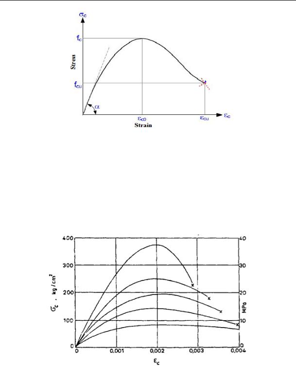
Concrete is a construction material with widespread use that is easily shaped by molds and has good resistance against pressure. While it has good resistance against pressure, it does not have sufficient ductility. For this reason, concrete elements need to be confined. Core concrete is confined with transverse reinforcement at certain intervals. Concrete cover is used in order to protect vertical and transverse reinforcements from external effects. The amount, diameter, interval, strength and order of transverse reinforcements, as well as reinforcement order, concrete strength and axial load affect concrete behavior. The typical stress-strain relationship of any concrete is given in Fig. 1.
93
Russian Journal of Building Construction and Architecture
Fig. 1. Stress-strain relation for any concrete class [6]
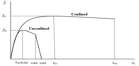
Concrete does not break when it reaches the greatest stress, it breaks when it reaches a certain deformation. The stress-strain features of concrete vary per concrete quality. The more the concrete has compressive strength, the less it has strain capacity; meanwhile the tilt at the beginning of the stress-strain curve (modulus of elasticity) increases and the peak points sharpen (Fig. 2).
Fig. 2. Stressstrain relation for different concrete classes [7]
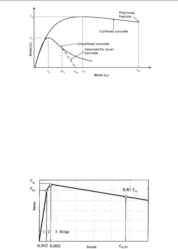
The graph which reveals the confined and unconfined concrete stress - strain relation is given at Fig. 3.
While the values regarding strength of materials used in structures are calculated, mathematical models are widely used. In the process of mathematically modeling for a material, the
94
Issue № 4 (36), 2017 |
ISSN 2542-0526 |
stress-strain (σ-ε) relationship of that material is used. The stress-strain relationship is related to the connections between the balance equations resulting from stress or force and conformity equations showing strain in material. During the analysis regarding these factors, the error margin varies per accuracy of stress-strain relationship of the material. Therefore, in order to facilitate the analysis, the (σ-ε) curves are simplified by idealization.
Fig. 3. Stress-strain relation for confined and unconfined concrete [8]
The simplified (σ-ε) curves used in structure design and assessment are called mathematical models. Mathematical models are needed to define concrete behavior under load as the strength problems of concrete are multivariate. In this study, four different models are used.
Mander et al. Nonlinear Concrete Model
This uniaxial model with fixed confinement is suggested by Mander et al (1988) [2]. Mander et al (1988) [2], have developed a model for concrete subjected compressive loading, and confined with either circular or rectangular sections, under static and dynamic axial compressive loading [9].
In this model, transverse confinement reinforcement creates a fixed effect of confinement and this strain calculated by given rules is deemed to be same throughout the entire stress-strain per unit. In the definition of this model, concrete compressive strength (fc), tensile strength (ft), strain per unit at greatest stress, modulus of elasticity (Ec) and specific weight parameters are required [10]. This model is used in Turkish earthquake regulation. In this model, by using moment-curvature relationship, final deformation criteria and plastic hinge length (Lp = h/2) [11], the plastic rotation capacity and hinge features of each element are defined [12]. The graph presenting the stress-strain relationship of this model is given in Fig. 4.
95
Russian Journal of Building Construction and Architecture
Fig. 4. Stress-strain relation for confined and confined concrete –Mander et al (1988) [13]
Trilinear Concrete Model
This is a simplified uniaxial trilinear concrete model that assumes no resistance to tension and features a residual strength plateau. It has calibration variation related to five different mechanical feature of concrete, such as compressive strength (fc1), initial rigidity (E1), post-peak rigidity (E2), residual (final) strength (fc2) and specific weight [10].
In this model, behavior is examined in three different areas. The first area is defined as a line until the 0.002 axial strain and in 0.002 axial shortening, the confined concrete stress is deemed equal to the non-confined element concrete strength [3]. Stress-strain graph for this model was given at Fig. 5.
Fig. 5. Stress –– strain relation for a trilinear stress-strain model [3]
96

Issue № 4 (36), 2017 |
ISSN 2542-0526 |
Chang-Mander Nonlinear Concrete Model
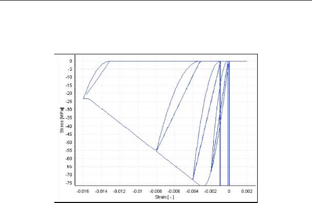
It is a model developed by Chang and Mander (1994) [4]. This concrete model, compared to other models featuring sudden changes in section models due to sudden fracture closing, especially prioritizes the transitions in stress-strain behaviors during fracture opening/closing. Concrete behavior under tensile, like it is under pressure, is repetitive and the model’s pressure and tensile envelopes control the slope of the stress-strain behavior at the origin as well as the increasing and decreasing parts of the same behavior (eg. pre-peak and post-peak parts). This model features eight parameters. These are; compressive strength (fc), tensile strength (ft), modulus of elasticity (Es), shortening per unit under greatest pressure, elongation per unit under greatest tensile stress, non-dimensional critical pressure shortening (Xcr-), nondimensional critical tensile elongation (Xcr +) and specific weight [10]. The graph of stressstrain for this model was given at Fig. 6.
Fig. 6. Stressstrain relation for ChangMander model [10]
Kappos ve Konstantinidis Nonlinear Concrete Model
It is an uniaxial, non-linear model with fixed effect of confinement, developed and programmed by Kappos and Konstantinidis (1999) [5]. It uses the constitutive relationship suggested bt Nagashima et al. (1992) [14] and its statistical calibration is made according to a very wide spectrum of experimental data. The effect of confinement provided by transverse confinement is treated by modified Sheikh and Uzumeri (1982) [15] factor (effect of confinement coefficient) and the existence of a fixed effect of confinement throughout the entire stress-strain definition range. In order to define this model, concrete compressive strength (fc),
97
Russian Journal of Building Construction and Architecture
tensile strength (ft), modulus of elasticity and specific weight parameters are required [10]. Fig. 7 gives stress-strain graphs for this model.
Fig. 7. Stressstrain relation for KapposKonstandtinidis model [10]
PerformanceBased Assessment
The importance of studies, researches and prevention about earthquake have risen after destructive earthquakes over the world especially in recent years. Earthquake damages will increase according to vulnerability of urban and rural building stocks. The size of earthquakes and the negative structural features will occur due to an increase in damage amount. Knowing the properties of buildings that have been negatively influenced in the seismic behavior of buildings under earthquakes will be put forward to ensure more serious approaches to reduce the level of damage risk as following earthquakes. In order to reduce the damages of the earthquakes, firstly the performance of buildings needs to be determined.
Earthquake safety of existing buildings has gained considerable importance after earthquakes which have occurred in our country especially in the last 30 years. Performance based assessment methods have been widely used in existing reinforced concrete structures.
In performance based design and assessment method, it is possible to determine in quantities the damage levels that may arise under the design ground motion within the structural system elements. It is checked whether this damage stays under the acceptable damage levels for each related element. Acceptable damage limits are defined in a way to be consistent with the foreseen performance targets at various earthquake levels [16, 17, 18].
98
Issue № 4 (36), 2017 |
ISSN 2542-0526 |
The assessment procedure aims to estimate the earthquake force demand at which the building would sustain the performance objectives. Demand spectrum, which is used in determining the performance of the building’s system, shows the maximum response that a building gives against seismic activities during an earthquake [19].
Two fundamental parameters of performance based design and assessment are earthquake demand and capacity [20, 21]. Earthquake demand represents the earthquake ground movement, whereas capacity represents building’s reaction under the effect of an earthquake. Structural capacity is represented by static pushover and capacity curve. This curve is derived by drawing the function between base shear force and building’s roof displacement. Capacity curve is derived with the calculation of building system with gravitational loads and proportionately increasing lateral forces up to the target point where structural capacity ends. The actual purpose of the nonlinear static method is to determine the target displacement of a building, then performing a final pushover analysis comes by increasing the lateral loads up to the target displacement. As a result, the demand values such as internal forces, rotations, strains and displacements are computed and the performance of the analyzed section is then evaluated with comparison of the strains obtained from the total curvature of the section with the upper boundary strains designated for different cross-sectional performance levels [22].
Based on structural dynamics theory, the modal pushover analysis procedure retains the conceptual simplicity of current procedures with invariant force distribution, and it is now common in structural engineering practice [23]. The POA has been widely used for its conceptual simplicity, computational attractiveness and capability of providing satisfactory predictions of seismic demands for low and medium-rise structures if the inelastic action is distributed over the height of the structures [24]. The pushover should be continued to the largest displacement practicable until the degradation of overall system occurs or limits of structural stability occur. In cases where a target displacement is set as a goal, it is generally worthwhile to push a little further to establish a better confidence level [25].
Building Example and Analysis Results
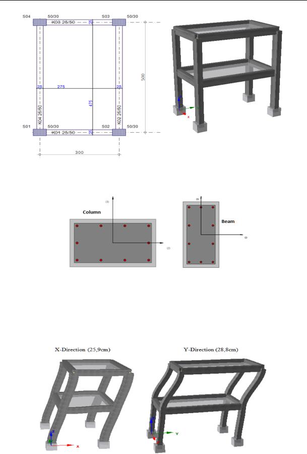
The reinforced concrete structure which is selected as an example has got 2 storeys, and the height of storey is 3 m for each storey. The material used in the structure is C30-S420. The reinforcements used in the beams and columns were selected as 14. The plan and 3D model of the structure is given at Fig. 8.
Columns were selected as 30*50cm, and beams were selected as 25×50cm. The transverse reinforcements (stirrups) which were used in both elements were selected as ϕ10/10. The columns and beams used in the structure are shown at Fig. 9.
99
Russian Journal of Building Construction and Architecture
Fig. 8. The blueprint and 3-D model of the building
Figure 9. The column and beam that used in this study
Maximum displacement values and deformation statuses which were calculated for the X and Y directions for each concrete model are given in Fig. 10.
Fig. 10 a. Deformation of building in both directions for Mander et al Nonlinear Concrete Model
100