

Russian Journal of Building Construction and Architecture
.pdfRUSSIAN JOURNAL
OF BUILDING
CONSTRUCTION AND ARCHITECTURE
1

The journal is indexed/abstracted in:
Web of Science Core Collection
(Emerging Sources Citation
Index)
(Thomson Reuters), USA
Ulrich's Periodicals Directory
(Bowker), USA,
DOAJ
(Lund University), Sweden,
Academic Search Complete
(EBSCO), USA,
SOCOLAR
(China Educational Publications Import and Export Corporation –– CEPIEC), China,
Google Scholar
(Google), USA,
E-Library
(ООО «РУНЭБ), Russia,
J-Gate
(Informatics Ltd), India
2
ISSN 2542-0526
RUSSIAN JOURNAL
OF BUILDING
CONSTRUCTION AND ARCHITECTURE
N 2 (38)
BUILDING STRUCTURES, BUILDINGS AND CONSTRUCTIONS
BASES AND FOUNDATIONS, UNDERGROUND STRUCTURES
HEAT AND GAS SUPPLY, VENTILATION, AIR CONDITIONING, GAS SUPPLY AND ILLUMINATION
WATER SUPPLY, SEWERAGE, BUILDING CONSTRUCTION OF WATER RESOURCES PROTECTION
BUILDING MATERIALS AND PRODUCTS
TECHNOLOGY AND ORGANIZATION OF CONSTRUCTION
DESIGNING AND CONSTRUCTION OF ROADS, SUBWAYS, AIRFIELDS, BRIDGES AND TRANSPORT TUNNELS
BUILDING MECHANICS
ENVIRONMENTAL SAFETY OF CONSTRUCTION AND MUNICIPAL SERVICES
THEORY AND HISTORY OF ARCHITECTURE, RESTORATION AND RECONSTRUCTION OF HISTORICAL
AND ARCHITECTURAL HERITAGE
ARCHITECTURE OF BUILDINGS AND STRUCTURES. CREATIVE CONCEPTIONS OF ARCHITECTURAL ACTIVITY
CITY PLANNING, PLANNING OF VILLAGE SETTLEMENTS
FIRE AND INDUSTRIAL SAFETY (CIVIL ENGINEERING)
Voronezh 2018
3
Russian Journal
of Building Construction and Architecture
Periodical scientific edition
Published since 2009 |
Comes out 4 times per annum |
Founder and publisher: Federal State Education Budget Institution of Higher Professional Education «Voronezh State Technical University».
The articles are reviewed and processed with the program ANTIPLAGIARISM. This publication cannot be reprinted without the prior permission of the publisher, references are obligatory.
Number of the certificate of registration of the media ПИ № ФС 77-67855
Issued by the Federal Service for Supervision of Communications, Information Technology, and Mass Media (Roskomnadzor)
Price is subject to change
EDITORIAL COUNCIL
The Head of the Council: Kolodyazhny S.A., rector (Voronezh State Technical University)
EDITORIAL BOARD
Editor-in-Chief: Melkumov V. N., D. Sc. in Engineering, Prof.
(Voronezh State Technical University)
Members:
Boldyrev А.М., Corresponding Member of the Russian Academy of Architecture and Engineering Science, D.Sc. in Engineering, Prof., Voronezh State Technical University, Russia
Bondarev B. А., D. Sc. in Engineering, Prof., Lipetsk State Technical University, Russia
Gagarin V. G., Corresponding Member of RAABS, Moscow State University of Civil Engineering, Russia
Gelfond А. L., Corresponding Member of the Russian Academy of Architecture and Construction Science, D. Sc. in Architecture, Nizhniy Novgorod State University of Architecture and Construction, Russia
Enin A. Ye., PhD in Architecture, Prof., Voronezh State Technical University, Russia
Karpenko N. I., Academician of RAABS, Research Institute of Building Physics (NIISF RAABS), Russia
Kirsanov М.N., D.Sc. in Physics and Mathemat-
ics, Professor (National Research University “Moscow Power Engineering Institute”)
Kobelev N. S., D. Sc. in Engineering, Prof., Southwest State University, Kursk, Russia
Kolchunov V. I., Academician of RAABS, Southwest State University, Kursk, Russia
Ledenyev V. I., D. Sc. in Engineering, Prof., Tambov State Technical University, Russia
Lyahovich L. S., Academician of RAABS, Tomsk State University of Architecture and Building, Russia
Mailyan L. R., D. Sc. in Engineering, Prof., Don State Technical University, Rostov, Russia
Panibratov Yu. P., Academician of RAABS, Saint Petersburg State University of Architecture and Civil Engineering, Russia
Podolsky Vl. P., D. Sc. in Engineering, Prof., Voronezh State Technical University, Russia (Dep. of the Editor-in-Chief)
Slavinskaya G.V., D. Sc. in Chemistry, Prof, Voronezh State Technical University, Russia
Suleymanov А. М., D. Sc. in Engineering, Prof., Kazan State University of Architecture and Engineering, Russia
Fyedorov V. S., Academician of RAABS, Moscow State University of Railway Engineering, Russia
Fedosov S. V., Academician of RAABS, Ivanovo State Polytechnic University, Russia
Chernyshov Ye. M., Academician of RAABS, Voronezh State Technical University, Russia
Shapiro D. M., D. Sc. in Engineering, Prof., Voronezh State Technical University, Russia
Shubenkov М. V., Academician of the Russian Academy of Architecture and Construction Science, D. Sc. in Architecture, Prof., Моscow Institute of Architecture (State Academy), Russia Asanowicz Alexander, Prof., Dr. of Sn., Technical University of Bialystok, Poland
Figovsky Oleg L., Prof., Dr. of Sn., Member of EAS, Israel Korsun V. I., D. Sc. in Engineering, Prof., The Donbas National Academy of Civil Engineering and Architecture, Ukraine Nguyen Van Thinh, Prof., Dr. of Sn., Hanoi University of Architecture, Vietnam
Editor: Kotlyarova E. S. |
Translator: Litvinova O. A. |
THE ADDRESS of EDITORIAL AND THE PUBLISHER OFFICE: 84 20-letiya Oktyabrya str., Voronezh, 394006, Russian Federation Tel./fax: (473)2-774-006; e-mail: vestnik_vgasu@mail.ru
Publication date 30.04.2018. Format 60×84 1/8. Conventional printed sheets 13.02. Circulation 500 copies. Order 95.
Published in Printing Office of Voronezh State Technical University 84 20-letiya Oktyabrya str., Voronezh, 394006, Russian Federation
ISSN 2542-0526 |
© Voronezh State Technical |
|
University, 2018 |
4
CONTENTS |
|
BUILDING STRUCTURES, BUILDINGS AND CONSTRUCTIONS ................................................... |
6 |
Fedorova N. V., Gubanova M. S. |
|
Crack-Resistance and Strength of a Contact Joint of a Reinforced Concrete |
|
Composite Wall Beam with Corrosion Damages Under Loading ............................................. |
6 |
HEAT AND GAS SUPPLY, VENTILATION, |
|
AIR CONDITIONING, GAS SUPPLY AND ILLUMINATION ........................................................ |
19 |
Kolosov A. I., Kuznetsova G. A., Gnezdilova O. A. |
|
Management of Work of Emergency and Recovery Services |
|
of a Gas-Distributing Organization ......................................................................................... |
19 |
WATER SUPPLY, SEWERAGE, BUILDING CONSTRUCTION |
|
OF WATER RESOURCES PROTECTION .................................................................................... |
27 |
Davydova E. G. |
|
Analysis of the Quality of Natural Water of a Reservoir Near an ore Extraction |
|
Plant Using the Method of Complex Assessment of Natural Water Pollution ........................ |
27 |
DESIGNING AND CONSTRUCTION OF ROADS, SUBWAYS, |
|
AIRFIELDS, BRIDGES AND TRANSPORT TUNNELS .................................................................. |
38 |
Yegorychev A. S., Kalgin Yu. I. |
|
Feasibility of Application of Bituminous Binder in Cast Asphalt Concrete Mixtures for |
|
Laying and Repairing Roadway Surfacing of a Highway Bridge............................................ |
38 |
Piletskii M. E., Didrikh I. V., Zubkov A. F., Tugolukov E. N. |
|
Pothole Maintenance of Non-Rigid Paving Surfaces Using the Injection Flow Method ........ |
47 |
BUILDING MECHANICS ............................................................................................................ |
58 |
Shapiro D. M., Tarasov A. A. |
|
Deformation Non-Linear Calcualtion of Non-Central Compressed Ferroconcrete Structures... 58
THEORY AND HISTORY OF ARCHITECTURE, RESTORATION AND RECONSTRUCTION |
|
OF HISTORICAL AND ARCHITECTURAL HERITAGE ................................................................ |
73 |
Ignatyeva V. O. |
|
Volumetric and Planning Structure and Construction Solutions of |
|
A. Gaudí’s Private Houses ....................................................................................................... |
73 |
ARCHITECTURE OF BUILDINGS AND STRUCTURES. |
|
CREATIVE CONCEPTIONS OF ARCHITECTURAL ACTIVITY .................................................... |
90 |
Bolshakov A. G. |
|
A Multi-Dimensional Grid As an Architectural Space and Foundation |
|
for Competencies in Architectural Training............................................................................. |
90 |
INSTRUCTIONS TO AUTHORS ................................................................................................. |
111 |
5

BUILDING STRUCTURES,BUILDINGS AND CONSTRUCTIONS
UDC 624.046
N. V. Fedorova1, M. S. Gubanova2
CRACK-RESISTANCE AND STRENGTH OF A CONTACT JOINT OF A REINFORCED CONCRETE COMPOSITE WALL BEAM WITH CORROSION DAMAGES UNDER LOADING
National Research University «Moscow State University of Civil Engineering» Russia, Moscow, tel.: +7-960-697-12-30, e-mail: fenavit@mail.ru
1D. Sc. in Engineering, Prof. of the Dept. of Reinforced Concrete and Stone Structures
Southwestern State University
Russia, Kursk, tel.: (4712)22-24-61, e-mail: asiorel@mail.ru 2Lecturer of the Dept. of Unique Buildings and Structures
Statement of the problem. The main problem with calculating ferroconcrete composite structures has to do with determining a shear modulus in the contact area of the elements of these structures. Considering a long-term mode character of their loading and likely corrosion damage during their operation, it is of interest to develop a deformation model and the of criteria and crack-resistance of the contact area of a composite flat stressed ferroconcrete structure.
Results. The model is suggested based on the deformation expressions for complex stressed reinforced concrete elements as well as a criterion of strength and crack resistance of a flat stressed corrosion-damaged element in the contact area of a ferroconcrete wall beam and physical equations for the reinforced concrete element with corrosion damages and intersecting cracks written in the form of relationships between finite stress and deformation increments. Compliance matrix of flat stressed reinforced concrete element is obtained that models the contact area of composite wall beam and takes in a count long-term deformation, corrosion damages and concentrated shear at intersections cracks formation.
Conclusions. The presented results can be used in practical methods of calculation of deformations and long-term strength of reinforced concrete composite structures operating with cracks. An example of calculating a reinforced concrete beam of a composite section is given. The calculation results are compared with the data of experimental studies and show effectiveness.
Keywords: reinforced concrete, flat-stressed element, corrosion, composite construction, scheme of intersecting cracks.
Introduction. The main problem of calculating ferroconcrete composites has to do with determining a specified shear modulus in the contact area of their elements. This parameter
© Fedorova N. V., Gubanova M. S., 2018
6

Issue № 2 (38), 2018 |
ISSN 2542-0526 |
depends on a construction solution for adjoining elements of a composite, scheme and intensity of longitudinal reinforcement, type of stress-strain, crack formation patterns, concrete type of the elements, etc.
Despite a great number of studies of deformation of ferroconcrete composites, they mainly deal with beam and rod structures with a one-axial stress-strain for certain reinforcement schemes [1, 5, 11—14, 17—19]. The theory of complex strained ferroconcrete structures operating with cracks was examined in a fundamental monography by N. I. Karpenko [6] and in [2] its variations for increments as applied to flat-strained wall-beams are discussed. Considering a long-term mode nature of stress of such structures and their likely corrosion, it is of interest to develop a deformation model and criteria of strength and crack resistance of the contact area of the elements of a composite flat-strained ferroconcrete structure.
1. Determining the stress-strain of a typical element. Let us look at a composite flatstrained ferroconcrete structure of a wall-beam consisting of three beams В1, В2 and В3 adjoined by contact joints that are crossed by a longitudinal reinforcement of the beam Asw (Fig. 1). The beam is loaded with an external load of concentrated forces P and an aggressive medium causing its corrosion.
A corrosion-damaged concrete layer
Element 1
Concrete 3
Concrete 2
Concrete 1
Fig. 1. Scheme of a corrosion-damaged ferroconcrete composite (wall-beam) (а) with a typical deformed finite element identified in the contact area (b):
h, b is the height and width of a ferroconcrete beam; l is the length of the beam; τxy are shearing forces in a typical element E1
Let us identify a typical element E1 of a single size in the contact area of two concretes whose stress-strain is determined by the applied normal Nx, Ny, and shear Nxy efforts. According to
7
Russian Journal of Building Construction and Architecture
[7], a relation between the normal and shear efforts and deformations of a typical element can be written as
|
|
|
C C C |
|
N |
|
|
|
|
|
|
|
|||||
|
x |
|
11 12 13 |
|
|
x |
, |
(1) |
y |
|
C21C22C23 |
|
Ny |
||||
|
|
|
C31C32C33 |
|
|
|
|
|
γxy |
|
|
Nxy |
|
|
|||
|
|
|
|
|||||
where εx, εy, γxy are relative deformations ; Nx, Ny, Nxy are normal and shear efforts in a typical flat-strained element of a single-size ; Cij are the coefficients of a compliance matrix of ferroconcrete.
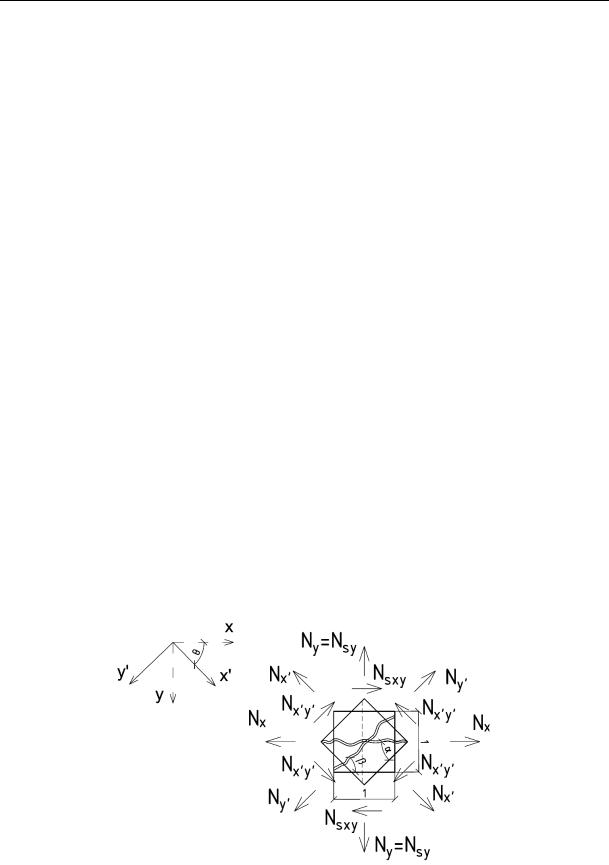
The dependencies of the deformation model [6, 18] hold true for all the values of an inclination angle of a crack in a typical element except α = 0° and α = 90° (Fig. 2) as the values of a relative shear of the reinforcement γsxy and shear efforts Nxy in these cases are zero. Therefore in order to design deformation dependencies in the specified anisotropic element E1 crossed by a horizontal crack along the contact joint of two beams, let us tunr the coordinate axis of the element x and y at the angle θ = 45° using the known transformation formulas (Fig. 2):
Nx'y '
x'y '
Nx Nxcos2 Ny sin2 2Nxycos sin ; |
|
Ny ' Nx sin2 Ny cos2 2Nxycos sin ; |
(2) |
Nxcos sin Nycos sin Nxy (cos2 sin2 ); |
|
x xcos2 y sin2 xycos sin ; |
|
y ' x sin2 y cos2 xycos sin ; |
(3) |
2 xcos sin 2 ycos sin xy (cos2 sin2 ). |
|
Fig. 2. Scheme of efforts in a typical flat-strained ferroconcrete element with crossing cracks: Nx’, Ny’, Nx’y’ are normal and shear efforts in the turned typical flat-strained element of a single size; Nsy, Nsxy are normal and shear efforts in the reinforcement bar
8
Issue № 2 (38), 2018 |
ISSN 2542-0526 |
In the investigated typical element as it reaches the limit efforts of crack formation, cracks tear the concrete in the direction of the contact joint and main stretching efforts. As a result, concrete loses its capacity to independently perceive the acting efforts. In this case only some concrete relations between the crack edges are retained and the concrete is still capable of resist tangential movements of the reinforcement bars crossing the crack in the areas between the cracks.
Let us denote respectively:
––α, β is an inclination angle of the crack along the contact joint of two beams and the crack of the main stretching efforts to the axis x;
––h is the thickness of a typical element;
––fsy* is the area of the reinforcement in direction to the axis y that takes up a length unit of a
typical element considering corrosion damage;
–– *sy is the reinforcement coefficient for the reinforcement in direction to y : *sy fsy* /h .
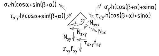
As a longitudinal crack forms in the contact joint of two concretes and cracks of the stretching efforts, all of the acting efforts in the typical element are diverted onto the reinforcement. As a result, there are normal and tangential strains in it (Fig. 3).
Fig. 3. Scheme of the efforts in the reinforcement following the formation of cracks in the typical element: σx’, σy’, τx’y’ are normal and shear strains in the turned typical flat-strained element of a single size; σsy, τsxy are normal and shear strains in the reinforcement bar;
Nзx, Nзxy, Nзy, Nзxy are linear cohesions of the inclined and longitudinal cracks respectively
In order to determine these stresses, let us project all the forces applied to the edges of the element on the axis x’ and y’:
–– onto the axis x’:
x'h(cos sin( x'y'h(cos( sin )
sy fsy cos sxy fsy cos Nзx'y' sin Nзx' cos Nзy 'x' cos( Nзy' sin( (4)
9

Russian Journal of Building Construction and Architecture
–– onto the axis y’:
y'h(cos( sin x'y'h(cos sin( )
sy fsy sin sxy fsy sin Nзx'y' cos Nзx' sin Nзy'x' sin( Nзy' cos(
2.Cohesion of crack edges through concrete relations. According to [1, 6], while presenting the relations of cohesion of the crack edges as evently distributed along the crack area, we can linear cohesion forces that occur in the cracks using the formulas
Nзx y ' hEзx'y ' x'y ' /lТ ;
Nзy 'x ' hEзy 'x' y 'x' /lТ ; |
(5) |
|
Nзx ' hEзx'ax' /lТ ; |
||
|
||
Nзy ' hEзy 'ay ' /lТ . |
|
Using the dependence of axial movements on the crack opening аi and a mutual displacement of its edges i and determining the axial displacements of the reinforcement as a function of average deformations of the reinforcement and concrete on the areas between the cracks, we get the following ratios for the components of the cohesion forces (see Fig. 3):
Nзx y ' (hEзx'y ' sx' cos hEзx'y ' sy ' sin /sin2
Nзy 'x' (hEзy 'x' sx' cos( hEзy 'x ' sy ' sin( /sin( 2 |
(6) |
|
Nзx' (hEзx ' sy ' cos hEзx' sx' sin /sin2 |
||
|
||
Nзy ' (hEзy ' sy ' cos( hEзy ' sx' sin( /sin( 2 |
|
where Езx`y, Езy`x, Езx, Езy` are secant moduli of drformations of cohesion forces determined according to the strength criterion [6] that in the first approximation can be assumed to be
Езx`y = Езx, Езy`x = Езy.
Let us express the elasticity using the dependencies suggested in [9] to determine the shear force following the formation of cracks considering the “peg” effect in the longitudinal reinforcement and occurring along the edges of the joint of the cohesion force displacement:
Eb Es,tot Eзn . |
(7) |
Using the hypothesis by V. M. Bondarenko [3] on the invariability of damage functions describing deficit of the value of the investigated factor of a disbalanced force resistance of concrete in relation to all the physical and mechanical characteristics of force resistance of concrete for a specified cohesion modulus during deformation of the crack edges can be written as
Eзn Ebφ. |
(8) |
3. Stresses occurring in the reinforcement bar. Assuming that in the investigated typical element the inclination angle of the longitudinal crack has a constant value α = 45. Inserting
10