

Учебное пособие 2203
.pdfIssue № 2 (38), 2018 |
ISSN 2542-0526 |
the expression (6) into the equation system (4) and expressing the stresses in the reinforcement τsy and σsy, we get
|
|
|
|
|
|
sy |
A1 x' A2 y' |
A3τx'y'; |
|
|
(9) |
||||||
|
|
|
|
|
|
τsy B1 x' B2 y' B3τx'y', |
|
|
|||||||||
|
|
|
|
|
|
|
|
|
|||||||||
where the coefficients of the equations are given by the formulas |
|
|
|
||||||||||||||
|
|
|
A1 ( 2 /4E 'sy μ)Eзx' ( 2 /4E 'sy μ)Eзx'y ' |
|
|
||||||||||||
( |
2(sin3β 2sin(3β/2)2 |
2sin(β/2)2 |
sinβ 2)/4E 'sy μ(2sinβ2 |
2))Esy ' |
|||||||||||||
( |
2(sin3β 2sin(3β/2)2 |
2sin(β/2)2 |
sinβ 2)/4E 'sy μ(2sinβ2 |
2))Eзy 'x' |
|||||||||||||
( |
2(sin(π/4 3β) 4sinβ2 |
4sin(β/2)2 |
2sin(π/4 β) 6)/8μ(sinβ2 1); |
||||||||||||||
|
|
|
A2 ( 2 /4E 'sy μ)Eзx' ( 2 /4E 'sy μ)Eзx'y ' |
|
|
||||||||||||
|
|
|
( 2 2cosβ2 |
2 |
2cosβsinβ/4E 'sy μcosβ)Eзy ' |
|
|
||||||||||
(2 2cosβsinβ 2 2cosβ2 |
2 |
2 /4E 'sy μcosβ)Eзy 'x' (cosβ sinβ 1)/2μ; |
|||||||||||||||
|
|
|
|
|
|
|
|
A3 (cosβ 1)/μ; |
|
|
|
(10) |
|||||
|
|
|
|
B1 ( 2 /4E 'sy μ)Eзx ' ( 2 /4E 'sy μ)Eзx'y ' |
|
|
|||||||||||
( |
2(cos2β sin2β/4E 'sy μcosβ)Eзy ' ( 2(cos2β sin2β/4E 'sy μcosβ)Eзy 'x' |
||||||||||||||||
|
( |
2( 2E 'sy /2 E 'sy sin(π/4 2β) |
2E 'sy cosβ)/4E 'sy μcosβ); |
||||||||||||||
|
|
|
B2 ( 2 /4E 'sy μ)Eзx' ( 2 /4E 'sy μ)Eзx'y ' |
|
|
||||||||||||
|
|
|
(2 2(cosβ2 |
2 |
2cosβsinβ-2 |
2)/4E 'sy μcosβ)Eзy ' |
|
||||||||||
|
|
|
(2 |
2(cosβ2 2 2cosβsinβ)/4E 'sy μcosβ)Eзy 'x' |
|
||||||||||||
|
(2E ' |
sy |
cosβ2 |
2E ' |
sy |
cosβ-2E ' |
sy |
cosβsinβ)/4E ' |
sy |
μcosβ);B sinβ/μ, |
|||||||
|
|
|
|
|
|
|
|
|
|
|
|
3 |
|
||||
where lcrc is the size of the area of relative mutual displacements of concrete and reinforcement in the area adjoining the crack [2];
E 'sy Es / ψst , |
(11) |
Es is the elasticity modulus of the reinforcement: ψst is |
the coefficient of averaging by |
V. I. Murashev [12]. |
|
4. Dependence of a flat-strained ferroconcrete in increments. As for intersecting cracks concrete loses its capacity to characterize the deformations of the element in any direction, the everage deformations of the reinforcement coincide with the general deformations of the element with cracks, for the investigated typical element in the axis x’ and y’ the deformations are
Δεx ' Δεsx '; Δεy ' Δεsy '; Δγx 'y ' Δγsx 'y '. (12) Considering the conditions of the compatibility of the displacements of the reinforcement bar in the crack and determining the axial displacements and those in direction of the axis x’ and
11
Russian Journal of Building Construction and Architecture
y’ of the reinforcement as a function of the average deformations of the reinforcement εs and concrete εb in the areas between the cracks and then expressing tangential movements using the compliance to the axial displacements at εb ≈ 0 and writing the deformations of the element with cracks in the axis x’ and y’, following the insertion of the stresses in the reinforcement τsy and σsy we can write the following ratios:
ε |
sx' |
( |
2(E ' |
sy |
A |
η |
τy |
Ek B )/2Ek E ' |
sy |
)σ |
x' |
( |
2(E ' |
sy |
A |
|
η |
τy |
Ek B )/2Ek E ' |
sy |
)σ |
y ' |
|
||||||||||
|
|
|
1 |
|
s |
1 |
|
s |
|
|
|
|
|
|
|
2 |
|
s |
2 |
s |
|
|
|||||||||||
|
|
|
|
|
|
|
( |
2(E ' |
sy |
A |
η |
τy |
Ek B )/2Ek |
E ' |
sy |
)τ |
x 'y ' |
; |
|
|
|
|
|
|
|||||||||
|
|
|
|
|
|
|
|
|
|
3 |
|
|
|
|
s |
3 |
s |
|
|
|
|
|
|
|
|
|
|
(13) |
|||||
ε |
sy ' |
( |
2(E ' |
sy |
A |
η |
τy |
Ek B )/2Ek E ' |
sy |
)σ |
x' |
( |
2(E ' |
sy |
A |
|
η |
τy |
Ek B )/2Ek E ' |
sy |
)σ |
y ' |
|||||||||||
|
|
|
1 |
|
s |
1 |
|
s |
|
|
|
|
|
|
|
2 |
|
s |
2 |
s |
|
|
|||||||||||
|
|
|
|
|
|
|
( |
2(E ' |
sy |
A |
η |
τy |
Ek B )/2Ek E ' |
sy |
)τ |
x'y ' |
. |
|
|
|
|
|
|
||||||||||
|
|
|
|
|
|
|
|
|
|
3 |
|
|
|
s 3 |
s |
|
|
|
|
|
|
|
|
|
|
|
|||||||
where νks is the elasticity coefficient that characterizes the ratio of the elastic deformations to the general deformations of the reinforcement; ητy is the coefficient that takes into account excessive compliance of reinforcement bars to tangential displacements that can be assumed to be 16 [6] in concrete at the boundary of the crack in the first approximation.
The dependencies (13) for two sequentially located loading steps i + 1 and i can be written in the increments of stresses and deformations in the reinforcement:
Δε |
sx' |
( |
2(E ' |
sy |
A |
η |
τy |
Ek B )/2Ek E ' |
sy |
)Δσ |
x' |
( |
2(E ' |
sy |
A |
|
η |
τy |
Ek B )/2Ek E ' |
sy |
)Δσ |
y ' |
|
||||||||||
|
|
|
1 |
|
s |
1 |
|
s |
|
|
|
|
|
|
|
2 |
|
|
s |
2 |
s |
|
|
||||||||||
|
|
|
|
|
|
|
( |
2(E ' |
sy |
A |
η |
τy |
Ek B )/2Ek E ' |
sy |
)Δτ |
x'y ' |
; |
|
|
|
|
|
|
||||||||||
|
|
|
|
|
|
|
|
|
|
3 |
|
|
|
s |
3 |
s |
|
|
|
|
|
|
|
|
|
|
(14) |
||||||
Δε |
sy ' |
( |
2(E ' |
sy |
A |
η |
τy |
Ek B )/2Ek E ' |
sy |
)Δσ |
x' |
( |
2(E ' |
sy |
A |
|
η |
τy |
Ek B )/2Ek E ' |
sy |
)Δσ |
y ' |
|||||||||||
|
|
|
1 |
|
s |
1 |
|
s |
|
|
|
|
|
|
|
2 |
|
|
s |
2 |
s |
|
|
||||||||||
|
|
|
|
|
|
|
( |
2(E ' |
sy |
A |
η |
τy |
Ek B )/2Ek E ' |
sy |
)Δτ |
x'y ' |
. |
|
|
|
|
|
|
||||||||||
|
|
|
|
|
|
|
|
|
|
3 |
|
|
|
s |
3 |
s |
|
|
|
|
|
|
|
|
|
|
|
||||||
In order to get a complete system of physical equations, let us determine an increment in the inclination angle Δγx`y` using the transformation formulas of relative deformations and stresses during the reverse turning of the coordinate axis. Inserting the values Δεsx` and Δεsy` from the equation (14) into the formulas we get the following initial inclination angle:
Δγ |
sx'y' |
(( |
2A 1)/ Ek )Δσ |
x' |
(( 2A |
1)/ Ek )Δσ |
y ' |
( 2A |
2)/ Ek ). |
(15) |
|
|
|
1 |
s |
2 |
s |
3 |
s |
|
|||
Inserting the increments of the deformations (14) and shear deformations (15) into the expressions (12), we get the following systems of physical ratios in the increments:
|
|
|
C12Δσy ' |
C13Δτx'y '; |
|
|||
Δεx' C11Δσx' |
(16) |
|||||||
Δεy ' C21Δσx' C22Δσy ' C23Δτx'y '; |
||||||||
Δγ |
x'y ' |
C Δσ |
x' |
C Δσ |
y ' |
C Δτ |
x'y ' |
. |
|
31 |
32 |
33 |
|
||||
Here the coefficients of the compliance matrix [Сij] of a flat element on the increments of stresses and deformations are given by the expressions
12

Issue № 2 (38), 2018 |
ISSN 2542-0526 |
|
|
|
|
|
|
|
k |
) |
|
|
|
|
|
|
|
k |
) |
|
|
|
|
|
k |
) |
|
|
|
|
C |
|
|
|
|
2(A1E 'sy B1ητy Es |
|
;C |
2(A2E 'sy B2ητy Es |
;C |
|
2(A3E 'sy B3ητy Es |
; |
|
|||||||||||||||
|
|
|
2Esk E 'sy |
|
2Esk E 'sy |
|
|
2Esk E 'sy |
|
|
||||||||||||||||||
|
11 |
|
|
|
|
12 |
|
|
|
|
13 |
|
|
|
|
|
|
|||||||||||
|
|
|
|
|
|
2(A1E 'sy B1ητy Esk ) |
|
|
|
|
|
2(A2E 'sy B2ητy Esk ) |
|
|
|
|
2(A3E 'sy B3ητy Esk ) |
|
|
|||||||||
|
|
|
|
|
|
|
;C |
|
|
|
;C |
|
|
|
; |
(17) |
||||||||||||
C |
21 |
|
|
|
|
|
|
|
22 |
|
|
|
|
|
|
23 |
|
|
|
|
|
|||||||
|
2Esk E 'sy |
|
|
2Esk E 'sy |
|
|
|
2Esk E 'sy |
|
|
||||||||||||||||||
|
|
|
|
|
|
|
|
|
|
|
|
|
|
|
|
|
|
|
||||||||||
|
|
|
|
|
|
2A1 1 |
|
|
|
2A2 1 |
|
|
2A3 2 |
|
|
|
|
|
|
|
|
|
|
|
|
|||
C |
31 |
|
;C |
|
|
|
;C |
. |
|
|
|
|
|
|
|
|
|
|
|
|||||||||
k |
|
|
|
|
|
|
|
|
|
|
|
|
|
|
|
|||||||||||||
|
|
|
|
|
32 |
|
|
|
k |
|
|
33 |
k |
|
|
|
|
|
|
|
|
|
|
|
||||
|
|
|
|
|
|
Es |
|
|
|
|
Es |
|
|
|
Es |
|
|
|
|
|
|
|
|
|
|
|
||
5. Physical ratios for a corrosion-damaged ferroconcrete element. The above analytical dependencies allow the compliance matrix to be designed Сij for a corrosion-damaged longterm deformed ferroconcrete element with cracks. A change in time of the deformation properties of a concrete neutralized with an aggressive medium during the formation of a matrix Сij can be considered using a change in the specified tangential deformation modulus in time:
E* |
(t) E*(t)φ;E* |
(t) E*(t)φ, |
(18) |
|
зn |
b |
зnt |
b |
|
where Eb*(t) is the dependence of change in the deformation modulus of concrete in time due to the effect of an aggressive medium.
In order to take into account the effect of an aggressive medium on the reinforcement bar, it is necessary that we determine over which period the aggressive medium reaches the reinforcement bar following the initial contact of the element with the aggressive medium. Let us denote the neutralization time of the protective layer of concrete as τ. Then the corrosion losses of the section of the reinforcement bar over the time of the effect of the aggressive medium during the formation of the compliance matrix Сij can be taken into account using a reduc-
tion in the reinforcement coefficient μ(t−τ) due to a reduction in the area of the section of the operating reinforcement bar in by means of the formula
(19) where fs(t − τ) is the area of the reinforcement in direction of y that accounts for a length unit of the typical element depending on the time of the effect of the aggressive medium
fs (t ) 0,25 (d 2 k (t ))2 , |
(20) |
d is the diameter of the specified reinforcement bar; d−2δк (t−τ) is the diameter of a noncorrosion damaged reinforcement bar in time; δк is the depth of neutralization of the reinforcement bar in time; h is the thickness of the typical ferroconcrete element.
Disruption in the cohesion of the corrosive reinforcement with concrete between cracks due to steel corrosion products are characterized with change in the cohesion coefficient
13

Russian Journal of Building Construction and Architecture
ψks. Change in time of the tangential coefficient of cohesion of the concrete reinforcement ψks(t − τ) as some analogue of the coefficient by V. M. Murashev is determined as a function of the average deformations of the reinforcement in the areas between the cracks. In the first approximation it can be assumed that as a result of the effect of the aggressive medium as the depth of corrosion of the reinforcement increases δк(t − τ), the cohesion coefficient ψks(t − τ) decreases proportionately to the depth of corrosion of the reinforcement.
Then a tangential deformation modulus of the reinforcement and average deformation modulus of the reinforcement in the corrosion-damaged element with cracks can be determined using the following expressions respectively:
Esk (t ) Es ks |
/ ks (t ), |
(21) |
E 'sy (t ) Es |
/ s (t ), |
(22) |
where Еs is the deformation modulus of the non-corrosion damaged reinforcement. Using the dependencies (18)—(22), the coefficients of the compliance matrix for the corrosion-damaged ferroconcrete with cracks on the increments of stresses and deformations can be written as follows:
|
|
k |
|
|
|
|
|
|
2(A E ' |
sy |
(t τ) B η |
τy |
Ek (t τ)) |
|
|
|
|
|||||||||||
|
|
|
|
|
|
|
|
|
|
|
||||||||||||||||||
C11(t) |
|
|
|
|
|
1 |
|
|
|
1 |
|
s |
|
|
; |
|
||||||||||||
|
|
|
|
|
2Esk |
|
(t τ)E 'sy (t τ) |
|
|
|
||||||||||||||||||
|
|
|
|
|
|
|
|
|
|
|
|
|
|
|
|
|||||||||||||
|
|
|
|
|
|
|
|
|
2(A E ' |
|
|
|
(t τ) B η |
|
|
|
Ek |
(t τ)) |
|
|
|
|||||||
|
|
k |
|
|
|
|
|
|
sy |
τy |
|
|
|
|||||||||||||||
|
|
|
|
|
|
|
|
|
|
|||||||||||||||||||
C12 |
(t) |
|
|
|
|
|
|
|
|
|
|
; |
|
|||||||||||||||
|
|
|
|
2Esk (t τ)E 'sy (t τ) |
|
|
||||||||||||||||||||||
|
|
|
|
|
|
|
|
|
|
|
|
|
|
|
|
|
|
|
|
|
|
|
|
|
|
|
|
|
|
|
k |
|
|
|
|
|
|
2(A E ' |
sy |
|
(t τ) B η |
τy |
Ek |
(t τ)) |
|
|
|
|
|||||||||
|
|
|
|
|
|
|
|
|
|
|
|
|||||||||||||||||
C13(t) |
|
|
|
|
3 |
|
|
|
|
3 |
|
s |
|
|
|
; |
|
|||||||||||
|
|
|
|
2Esk |
|
(t τ)E 'sy (t τ) |
|
|
||||||||||||||||||||
|
|
|
|
|
|
|
|
|
|
|
|
|
|
|
||||||||||||||
|
|
|
|
|
|
|
|
|
2(A1E 'sy (t τ) B1ητy Esk (t τ)) |
|
|
|
|
|||||||||||||||
|
|
k |
(t) |
|
|
; |
|
|||||||||||||||||||||
|
|
|
|
|||||||||||||||||||||||||
C21 |
|
|
|
|
|
|
|
|
|
|
|
|
|
|
|
|
|
|
||||||||||
|
|
|
|
|
|
k |
(t τ)E 'sy (t τ) |
|
|
|
||||||||||||||||||
|
|
|
|
|
|
|
|
|
|
2Es |
|
|
|
|
|
|
|
|||||||||||
|
|
k |
(t) |
2(A E ' |
|
|
|
(t τ) B η |
|
|
Ek (t τ)) |
; |
(23) |
|||||||||||||||
|
|
|
|
|
|
|||||||||||||||||||||||
C22 |
2 |
|
|
|
sy |
|
2 |
|
|
τy s |
|
|
|
|||||||||||||||
|
|
|
|
|
|
|
|
|
|
|
|
|
|
|
|
|
|
|
|
|
||||||||
|
|
|
|
|
|
|
|
|
|
2Esk (t τ)E 'sy (t τ) |
|
|
|
|
||||||||||||||
|
|
k |
|
|
|
|
|
|
2(A E ' |
|
|
|
(t τ) B η |
|
|
|
Ek |
(t τ)) |
|
|
|
|||||||
|
|
|
|
|
|
|
|
sy |
τy |
|
|
|
||||||||||||||||
C23 |
(t) |
|
|
|
|
|
|
|
; |
|
||||||||||||||||||
|
|
2Esk (t τ)E 'sy (t τ) |
|
|
||||||||||||||||||||||||
|
|
|
|
|
|
|
|
|
|
|
|
|
|
|
|
|
|
|
|
|
|
|
|
|
|
|
|
|
|
|
31k |
(t) |
2A1 1 |
; |
|
|
|
|
|
|
|
|
|
|
|
||||||||||||
C |
|
|
|
|
|
|
|
|
|
|
|
|||||||||||||||||
|
|
|
|
|
|
|
|
|
|
|
|
|
||||||||||||||||
|
|
|
|
|
|
|
|
Esk (t τ) |
|
|
|
|
|
|
|
|
|
|
|
|
|
|||||||
|
|
|
|
|
|
|
|
|
|
|
|
|
|
|
|
|
|
|
|
|
|
|||||||
|
|
32k |
|
|
|
|
|
|
2A2 1 |
|
|
|
|
|
|
|
|
|
|
|
|
|
||||||
|
C |
(t) |
; |
|
|
|
|
|
|
|
|
|
|
|
||||||||||||||
Esk (t τ) |
|
|
|
|
|
|
|
|
|
|
|
|||||||||||||||||
|
|
|
|
|
|
|
|
|
|
|
|
|
|
|
|
|
|
|
|
|
|
|||||||
|
|
|
|
|
|
|
|
|
2A3 2 |
|
|
|
|
|
|
|
|
|
|
|
|
|
||||||
|
|
k |
(t) |
|
. |
|
|
|
|
|
|
|
|
|
|
|
||||||||||||
|
|
|
|
|
|
|
|
|
|
|
|
|
||||||||||||||||
C33 |
|
|
|
|
|
|
|
|
|
|
|
|
|
|
|
|
|
|
|
|||||||||
k |
τ) |
|
|
|
|
|
|
|
|
|
|
|
|
|||||||||||||||
|
|
|
|
|
|
|
|
|
Es (t |
|
|
|
|
|
|
|
|
|
|
|
|
|
||||||
|
|
|
|
|
|
|
|
|
|
|
|
|
|
|
|
|
|
|
|
|
|
|
|
|
|
|
|
|
14
Issue № 2 (38), 2018 |
ISSN 2542-0526 |
6. Calculation example. In order to test the obtained deformation dependencies of the typical flat-strained ferroconcrete element, a calculation of the ferroconcrete wall-beam of a composite section loaded with two symmetrically positioned cocnrentrated forces in the areas adjoining the support was performed. The sizes of the structure as well as the concrete type are accepted to be the same as in the experimental beam structures [8, 10].
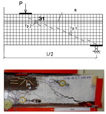
For a calculation analysis the typical elements are investigated in the area of the formation of inclined cracks including the element E1 positioned at the boundary of contact of two concretes (Fig. 4). The strength and deformation characteristics of concrete for the typical element E1 and the sizes of this element are specified according to the guidelines [5, 8].
а)
Contact area
b)
Fig. 4. Тheoretical (a) and experimental (b) pictures of crack formation at different stages of laoding the structure
The calculation results as a theoretical picture of the formation of the inclined cracks in the wallbeam structure are presented in Fig. 4. Here in order to compare, there is a picture of the cracks in the same structure obtained experimentally [10]. As shown in Fig., in the investigated composite structure along with non-intersecting inclined cracks caused by the main stretching stresses (crack 1) there are intersecting cracks (crack 2) in the area of the contact joint of the composite. Crack resistance and strength of the investigated flat-strained element in the area of the contact joint was evaluated for a beam structure of the new concrete damaged with corrosion
15
Russian Journal of Building Construction and Architecture
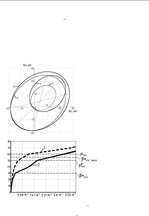
(Fig. 5). The resulting crack resistance criteria are in agreement with the calculation diagram of relative shear deformations of the typical element E1 (Fig. 6). The formation of cracks along the contact joint under the load Pcrc* leads to a significant increase in the shear deformations in the investigated element. As the load increases up to Pcrc* and there are intersecting cracks in the typical element (an inclined crack and cracks along the contact joint), there is another more significant increase in the shear deformation. At this laoding level Pcrc* the shear resistance is only observed in the reinforcement bars before there is fluidity in them (see the strength criteria of the element E1 in Fig. 5).
Load on the beam, kH
Relative shear γxy
Fig. 5. Crack resistance and strength criteria of the typical flat-strained element in the contact area:
1 for the beam of the new concrete (t = 0); 2 for the beam of the new concrete (t = 0) following the formation of intersecting cracks; 3 for the beam of the concrete under the effect of the aggressive medium (t = 900);
4 for the beam of the concrete under the effect of the aggressive medium (t = 900) following the formation of intersecting cracks;
N1, N2 are the main efforts in the typical flatstrained element of a single size
1 for the new concrete (t = 0);
2 for the concrete under the effect of the aggressive medium (t = 900)
Fig. 6. Graph of changes in the relative shear caused by loading: Pcrc* is a calculation load of the formation of the longitudinal crack along the joint for a corrosion-damaged element; Pcrc* is a calculation load of the formation of the inclined crack for the corrosion-damaged element; Pcrc* эксп is an experimental load of the formation of the longitudinal crack along the joint of the corrosion-damaged element; Рcrc is a calculation load of the formation of the inclined crack for the non-corrosion damaged element
16
Issue № 2 (38), 2018 |
ISSN 2542-0526 |
Conclusions
1.The resulting calculation model of a long-term deformation of a flat-strained corrosiondamaged ferroconcrete element in the contact area of two concretes allows one to determine the stress-strain of the composite ferroconcrete flat-strained structure operating with cracks in the contact area of two beams considering a long-term deformation, corrosion of concrete and reinforcement.
2.The presented results can be employed in practical methods of calculating deformations and long-term strength of ferroconcrete composites operating with cracks. The efficiency of this calculation was shown compared to the results of a calculation involving experimental studies.
References
1.Bashirov Kh. Z., Kolchunov Vl. I., Fedorov V. S., Yakovenko I. A. Zhelezobetonnye sostavnye konstruktsii zdanii i sooruzhenii [Reinforced concrete composite structures of buildings and constructions]. Moscow, ASV Publ., 2017. 248 p.
2.Bondarenko V. M., Kolchunov Vl. I. Raschetnye modeli soprotivleniya zhelezobetona [Design models of reinforced concrete resistance]. Moscow, ASV Publ., 2004. 471 p.
3.Bondarenko V. M. Silovoe deformirovanie, korrozionnye povrezhdeniya i energosoprotivlenie zhelezobetona
[Force deformation, corrosion damage and energy resistance of reinforced concrete]. Kursk, 2016. 67 p.
4.Geniev G. A., Kissyuk V. N., Tyupin G. A. Teoriya plastichnosti betona i zhelezobetona [The theory of plasticity of concrete and reinforced concrete]. Moscow, Stroiizdat Publ., 1974. 316 p.
5.Gornostaev I. S., Klyueva N. V., Kolchunov V. I., Yakovenko I. A. Deformativnost' zhelezobetonnykh sostavnykh konstruktsii s naklonnymi treshchinami [Deformability of reinforced concrete composite structures with inclined cracks]. Stroitel'naya mekhanika i raschet sooruzhenii, 2014, no. 5 (256), pp. 60—66.
6.Karpenko N. I. Teoriya deformirovaniya zhelezobetona s treshchinami [Theory of deformation of reinforced concrete with cracks]. Moscow, Stroiizdat Publ., 1976. 205 p.
7.Karpenko N. I., Karpenko S. N., Petrov A. N., Palyuvina S. N. Model' deformirovaniya zhelezobetona v prirashcheniyakh i raschet balok-stenok i izgibaemykh plit s treshchinami [Model of deformation of reinforced concrete in increments and calculation of beams, walls and bending plates with cracks]. Petrozavodsk, Izd-vo PetrGU, 2013. 156 p.
8.Klyueva N. V., Karpenko D. V., Kashchavtsev A. A. Metodika eksperimental'nykh issledovanii prochnosti i treshchinostoikosti po naklonnym secheniyam nagruzhennykh i korrozionno povrezhdennykh zhelezobetonnykh sostavnykh konstruktsii [The technique of experimental studies of strength and fracture toughness on inclined sections of loaded and corrosion-damaged reinforced concrete composite structures]. Stroitel'naya mekhanika inzhenernykh konstruktsii i sooruzhenii, 2015, no. 5, pp. 77—80.
9.Kolchunov V. I., Panchenko L. A. Raschet sostavnykh tonkostennykh konstruktsii [Calculation of composite thin-walled structures]. Moscow, ASV Publ., 1999. 281 p.
17

Russian Journal of Building Construction and Architecture
10.Kolchunov V. I., Gubanova M. S., Karpenko D. V. Raschetnaya model' dlitel'nogo deformirovaniya ploskonapryazhennogo korrozionno povrezhdennogo zhelezobetonnogo elementa v zone kontakta dvukh betonov [Calculation model of long-term deformation of a plane-stressed corrosion-damaged reinforced concrete element in the contact zone of two concretes]. Stroitel'naya mekhanika inzhenernykh konstruktsii i sooruzhenii, 2017, no. 1, pp. 49—57.
11.Kolchunov Vl. I., Yakovenko I. A., Lymar' Ya. V. Zhestkost' zhelezobetonnykh sostavnykh konstruktsii pri nalichii razlichnykh treshchin [Rigidity of reinforced concrete composite structures in the presence of various cracks]. Stroitel'stvo i rekonstruktsiya, 2015, no. 5 (61). pp. 17—24.
12.Murashev V. I. Treshchinoustoichivost', zhestkost' i prochnost' zhelezobetona [Fracture resistance, stiffness and strength of reinforced concrete]. Moscow, ASV Publ., 1950. 472 p.
13.Fedorov V. S., Bashirov Kh. Z., Kolchunov Vl. I. Elementy teorii rascheta zhelezobetonnykh sostavnykh konstruktsii [Elements of the theory of calculation of reinforced concrete composite structures]. Academia. Arkhitektura i stroitel'stvo, 2014, no. 2, pp. 116—118.
14.Brown R. D. Design Prediction of the Life for Reinforced Concrete in Marine and Other Chloride Environments. Durability of Building Materials, 1982, vol. 1, pp. 113—125.
15.Frangopol D. M. Reliability of reinforced concrete girders under corrosion attack. J. Struct. Eng., 1997, vol. 123 (3), pp. 286—297.
16.Klueva N., Emelyanov S., Kolchunov V., Gubanova M. Criterion of crck resistance of corrosion damaged concrete in plane stress state. Procedia Engineering, 2015, no. 117, pp. 179—185.
17.Kolchunov V., Androsova N. Durability corrosion concrete at simultaneous manifestation of power and environmental influences. Building and Reconstruction, 2013, no. 5, pp. 3—8.
18.Liu Y. Modeling the Time-to-Corrosion Cracking of the Cover Concrete in Chloride Contaminated Reinforced Concrete Structures. Virginia, USA, 1996. 128 p.
19.Prudil S. Mathematical expressions of concrete changes due to corrosion. Acta Univ. Agric. Brno, 1977, no. XXV, pp. 109—119.
20. Saetta A. The numerical analysis of chloride penetration in concrete. J. ACI Mat, 1993, vol. 90 (5), pp. 441—451.
18

Issue № 2 (38), 2018 |
ISSN 2542-0526 |
HEAT AND GAS SUPPLY,VENTILATION,
AIR CONDITIONING,GAS SUPPLY AND ILLUMINATION
UDC 696.2
A. I. Kolosov1, G. A. Kuznetsova2, O. A. Gnezdilova3
MANAGEMENT OF WORK OF EMERGENCY AND RECOVERY SERVICES
OF A GAS-DISTRIBUTING ORGANIZATION
Voronezh State Technical University
Russia, Voronezh, tel.: (4732)71-53-21, e-mail: kolossn@yandex.ru
1PhD in Engineering, Assoc. Prof. of the Dept. of Heat and Gas Supply and Oil and Gas Business, 2PhD in Engineering, Assoc. Prof. of the Dept. of Heat and Gas Supply and Oil and Gas Business National Research University «Moscow State University of Civil Engineering»
Russia, Moscow, tel.: (4712) 22-26-17, e-mail: tgv-kstu6@yandex.ru
3PhD in Engineering, Assoc. Prof. of the Dept. of Heat and Gas Supply and Ventilation
Statement of the problem. When eliminating emergencies of gas supply systems, the most rational strategy for the actions of dispatching personnel is based on the management of the operation of emergency recovery services that allow one to monitor the restoration and to distribute limited material and technical resources considering changes in the parameters over time.
Results. On the basis of the mass service theory, an algorithm was developed to determine the optimal structure and parameters of the emergency service of the gas distribution company. To predict the parameters of the emergency services, a software is developed in the environment of the MatLab-Simulink package, which allows flexible control over the reliability of the equipment depending on the changing conditions of its operation. The program has advanced graphical representation of the results.
Conclusions. The use of the developed program allows one to increase the efficiency of the repair departments of a gas distribution organization and to maintain a high level of safety of operation of gas equipment.
Keywords: gas supply, accident, recovery, repair service, gas-distribution organization, MatLab — Simulink, modeling.
Introduction. The most viable strategy for managing dispatching staff that allows one to oversee restoration process and distribute limited material and technical resources considering changes in particular parameters over time is central to activities of emergency services.
© Kolosov A. I., Kuznetsova G. A., Gnezdilova O. A., 2018
19

Russian Journal of Building Construction and Architecture
1.Model of processing emergency claims based on the mass service theory. Each emergency has its own features and a certain mechanism [1, 2, 4, 8]. As an energency is being handled, there are the following problems a dispatcher has to address: 1) identifies damaged spots and scales; 2) collects the data on how an emergency develops; 3) evaluates an average time for handling an emergency; 4) evaluates risk-reduction costs: technical, environmental, economic, etc.; 5) identifies a few options and works out the most viable one.
Making an informed decision is challenging and complex. Therefore a dispatcher has to be properly informed and experienced and capable of making decisions within a short time period. It can be reduced by means of the following: 1) correct and timely prediction of emergencies and regular updates. This might be done by processing statistical data, modern monitoring tools or previously developed models; 2) preliminary calculations to allow one to identify spots and amount of damage of gas distribution networks caused by an emergency; 3) evaluating costs, average time of an emergency and choosing the most viable option for eliminating it considering different scenarios.
All of these enable a dispatcher to monitor works as well as to make changes to the way they are carried out. In order to determine the impact of an emergency, it is necessary to investigate degradation factors that affect gas distribution networks during their operation. These processes cause changes in the initial overall condition of elements of gas distribution system.
2.Model of handling emergency demands. Based on the theory of mass service, an algorithm of identification of an optimal structure and parameters of operation of emergency work to provide a level of safety of gas distribution networks was developed based on a necessary index of a restoration flow for a required level of safety. An emergency service was considered as a multi-channel mass service system where each emergency team is presented as a service channel [9, 13, 16, 17]. It is suggested that a ratio of mathematical anticipation of an amount of operating elements of the equipment group to the total number of elements in a group is employed as a criteria for evaluating an emergency:
Ki t mi1 t . Ni
A workload index for handling emergency demands is as follows:
n
Пзi
|
n |
, |
|
i 1 |
|
Пвi
i 1
where Пзi is a flow of emergency demands of the i-th equipment group, unit year−1; Пвi restoration flow of the i-th equipment group, unit year−1.
(1)
is a
20