

Operations technology
1. Edge soil is cut off on the road after reconstruction using the soil for widening of roadbed lower than road pavement. 2. Surfacing edge is cut off by disc saws on tractor. 3. After roadbed widening and compaction up to the lower surfacing of additional layer of base material is poured out for this course widening. 4. Material for foundation widening is placed and compacted, level with it subgrade soil is poured out within the new formed side of road.5. There is constructed old surfacing widening, laid shaping course and new surface course is laid onto the whole width of surfacing.
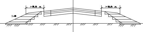
While widening carriage way old roadbed of smaller width up to 1,0-1,55m is left. It is widened layer –by- layer (fig. 6.1,b).
Technology.
1. After width lane layout soil and material of reinforced edge is scarified on this lane. Loosening of future trench is executed by any machine – scarifiers on motor grader, on roller or any other self-propelled machines. 2. Along road pavement edge there is constructed road bed for widening lane of design width up to the bottom of foundation additional course. Bottom of the road trough is with cross slop of 30120‰ to the side of the road direction to provide drainage from the foundation. At tranches excavation there are applied Trenches are made by chain-bucket excavators, trench excavators or motor grader.3. The next step is: the trenches are filled with design materials. 4. Material is delivered to trenches and distributed by motor grader at the surface edge and then it is moved into trench. 5. Material is flatted by motor grader and compacted by special hinged rollers or any other means. 6. Crushed stone for foundation is distributed by crushed stone paver. 7. It is reasonably to distribute and compact courses by paver of type ДС-7Shaping and upper courses are constructed according to general technology developed for the very type of operation. Double sides symmetric widening can be executed by two methods analogical to one side widening (see fig. 6.1), but here widening are made from both sides simultaneously without construction of shaping course (fig. 6.2).
Fig. 6.2. Diagram of double sided asymmetric widening of road pavement and roadbed
Chain – basket excavators, trench diggers and some other machine accessories including hanged and pull-type ploughs are used for construction of lanes of small width (0,25-0,75 м) 0,25 м carriage way widening is the most complicated because preparation of narrow bank and foundation compaction mechanically is very difficult. That is why such widening is tried to escape. Small widening can be done as lanes of
36
two paving mosaic blocks rows or some rows of block. Paving blocks or mosaic block are placed on sand, crushed stone or gravel material.
6.2. The most complicated task at carriage way widening is the solid conjugation of existing or widening road pavement. That is why it is necessary to follow some requirements:
–structural courses of widening for better conjugation should have material thickness and properties close resemblance to materials used in courses of existing road pavement. And lane durability should be stronger that old road pavement one;
–widening lane durability is to be equal to durability of main part of road
pavement. It is necessary to control compaction process;
–after road pavement widening carriage way is covered with asphalt concrete taking into consideration that longitudinal junction does not coincide with points of conjugation of existing and widening road pavement;
–to protect cracks formation under conjugations of existing and widening road pavement interlayer from rigid obtaining synthetic material minimal stretchability.
Top course of asphalt concrete is recommended to make from polymeric asphalt concrete mix.
6.3. For speed increasing and traffic safety construction of edge reinforced lanes and edges comparable with width increase of carriage way. Regime and traffic safety has direct dependence on width of reinforced road surfacing which provides size of physiologically safety corridor.
If there is edge lane and reinforced side of road capacity of road with double lanes carriage section increases by 15-30%. The more so edge lanes make road have finished and attractive form.
Edge lanes are constructed of the same type as road pavement of main road without special activities. Edge lane of marking should play this role.
Technology of road pavement construction on edge lanes and on edges is analogical to trench widening.
For traffic safety adhesion factor of wheel with surfacing on edges does not differ more than by 0,15 from the coefficient of adhesion on carriage way.
While choosing edge lane construction edge lane from materials treated with mineral bindings including cement is more suitable. Thickness of such a course is 2022cm. This lane has high mechanical durability, it is lighter, and technology of construction of edge lane from monolithic concrete becomes easy thanks to narrow grabbing concrete placer (type gomako).
Edge lanes can be also constructed from prefabricated slabs of white concrete
with thickness of 6cm on ordinary monolithic concrete.
While placing edge slabs along existing surfacing the following operations are
done:
–there is arranged small ditch for edge lane;
–edges of old surfacing are flatted;
–foundation is leveled with distribution of flatting material;
–cement concrete course is placed and compacted;
37

–there are placed slabs from white concrete and carefully match them with surfacing edges with cement mix for leveling, add soil from the side of edge and compact it;
–fill longitudinal and cross seams with concrete, bitumen mastics or cement mix.
There is technological break between operations of concrete mix application and slabs placing.
Double layer slabs are recommended – lower course from ordinary concrete but upper layer is from colored concrete. Applied slabs are of 0,75 m width and 0,2 m length.
Shortcomings: high cost of edge lanes’ they are obstacles at surface treating and now surfacing course placing. In this case it is necessary to remove slabs of edge lanes, lift them onto new remark and put them on new cement concrete layer or mortar. As a result some slabs will be broken.
It is more economical to make edge lanes from monolithic concrete on the place before road pavement construction (fig. 6.3). For that there is applied side wood shuttering and movable bunkers for cement concrete mortar and a bit improved shuttering made of planks stood edgewise.
Planks have exact sizes on height relative to concrete edge lane thickness. On external planks sides two metal lugs one over the other are fixed in 0,6-1,0 m along. Planks are fixed vertically on exact distance from each other with the help of metal frames with square profile relative to profile of lugs holes. Frames ends passed through planks shuttering and these frames support shuttering.
After shattering placing the space between planks is filled with cement concrete mortar, compacted by vibrators and spattered with film forming materials. In every 10m in edge lane there are arranged expansion joints. After shattering removal edges are covered with soil and concrete slabs are placed on surfacing.
a) |
|
|
|
|
|
c) |
|
|
|
|
|
|
|
|
|
|
|
|
|
|
|
|
|
|
|
|
|
|
|
|
|
|
|
|
|
|
|
|
|
|
|
|
|
|
|
|
|
|
|
|
|
|
|
|
|
|
|
|
|
|
|
|
|
b) |
d) |
|
Fig. 6.3. Order of construction of road side from monolithic concrete:
а) shattering placing; b) laying of concrete; c) curbs removal and side edge surface of concrete removal; d) edges feel and surfacing placing
38
1 – metal frame; 2 – planks stood edgewise; 3 – shuttering; 4 – foundation; 5 – concrete; 6 – bitumen lubrication; 7 – surfacing.
UNIT VII
VARIANTS OF ROAD PAVEMENT COURSES REMOVAL AND THEIR RECAPTURE
7.1.Variants of road pavement reconstruction.
7.2.Technological operations at full removal of road pavement.
7.3.Partial removal of road pavement.
7.4.Assessment of possible application of road pavement material which are
removed.
7.1. In the cases when red marks do not practically need changes different variants of road bed reconstruction are possible, they are chosen according to technical-economic considerations.
а) Full removal of existing road pavement with application of received material while constructing new road pavement, reinforcement of edges, constructing of bypass roads etc.
Full road pavement removal is made in the following cases: 1) strength fact of existing road; 2) drainage course cannot execute its functions because of silting and destruction; 3) frequent breaches on more than 3% of terrain are on road pavement.
b)Destruction of existing road pavement especially courses from monolithic materials and its use as upper layer of foundation. In this case the possibility of protection of reflecting cracks appearance in upper layers of surfacing is increased.
This variant of reconstruction is applied when existing road pavement includes layers from cement concrete of different types or materials reinforced with significant amount of concrete and saved their monolithic properties but reducing evenness of road pavement surfacing and having significant amount of cracks. Some blocks of destroyed course should not increase 0,5 m. Asphalt concrete surfacing is fully or partly removed by method of cold milling, further it is used on asphalt concrete plant as additive for production of new asphalt concrete mix or for reinforcement of edges without treatment.
Destructive layer before laying of upper layer should be completely compacted.
c)Destruction of existing road pavement, widening and its reinforcement with new material with placement of existing upper layers.
d)Saving of existing road pavement, its patching or heat, cold or combined regeneration of asphalt concrete surfacing with following placement of reinforced layer.
Synthetic materials are used for protection of reflected cracks.
39
This method of reconstruction is reasonable technically and economically at strength factor of existing road pavement more than 0,8 and surfacing condition allowing execution of corresponding operations.
e) Saving of existing road pavement its widening, patching repair cold or combined regeneration synthetic net placement and construction of reinforced layers.
7.2. Technology of complete removal of existing road pavement including following operations:
–layerwise loosening of existing surfacing and foundation;
–shifting of destructed material;
–loading of destructive material.
Layerwise loosening of layers is executed by bulldozer with hanged ripper for some parallel passes along carriage way.
Shifting of material is executed by bulldozer loading material out on distance of 15-20m from each other.
Materials are loaded into tracks by front single-bucket loaders and excavators. 7.3. Partly removal of road pavement is used in the cases when leveling of
existing surfacing is needed; removal of upper loose ground of surfacing; it is necessary to decrease thickness of existing surfacing before placing of new layer for leveling or for reinforcement of existing road pavement without change of vertical marks of its surfacing.
In order to remove upper layer partly there are applied machines for cold milling. It can provide:
–necessary depth of milling;
–designed profile inclination;
–designed longitudinal inclination;
–cleanness of edge of milling.
There are significant number of machines types for cold milling of surfacing from 1,3 up to 4,5m at maximal depth of milling from 150 up to 300m.
At existing surface from crushed stone and gravel it is loosened in existing depression depth, profiled and compacted. Then there are placed layers of reinforcement as improved surfacing. For loosening and profiling motor grader with hanged scarifier can be used, selfpropelled rollers on pneumatic tires or combined ones are applied for compacting.
7.4. For assessment of possibility of application of materials received at existing road pavement removal there are executed:
–visual assessment of materials condition and preliminary definition of structure type in which they can be used
–determination of works type, necessary for making materials be in good condition suitable for their application
–development of technology of construction of designed structures with application of the very materials including methods of treatment with bindings, regeneration of old asphalt concrete or products of milling of asphalt concrete in plant.
40
– technical – economic assessment of application of old pavement product after removal in different structures in comparison with application of new materials
After determining the kind of structure where old pavement material is used it is tested in laboratories.
In the case of products treatment with bindings designing of mortars is done according to the standards.
UNIT VIII
METHODS OF ROAD PAVEMENT AND SURFACING
REGENERATION
8.1.Methods of regeneration and recycling.
8.2.Thermo profiling and thermo plasticization.
8.3.New technologies of hot regeneration.
8.4.Methods of cold regeneration.
8.5.Asphalt grain concrete mortars.
8.6.Methods of cold-hot regeneration.
8.1.With regards to road pavement and carpet regeneration means reconstruction of their strength properties, evenness, continuity etc. With regards to old asphalt concrete regeneration is treatment or recycling of it in order to change its positive properties.
It is necessary to differ the following terms: regeneration and repeated use of old carpet, which is cold recycling.
Recycling is the operation without regeneration of material properties
It provides obligatory restoration of material properties or its repeated use (recycling).
There are following methods of regeneration and recycling, which can be applied during road reconstruction:
– method of hot regeneration on the road with application of different methods of heating, loosening and improvement of old asphalt concrete properties with further its placing onto surfacing;
– method of cold regeneration on road when old road pavement material is removed by cold milling, treated with bitumen emulsion or cement and placed into bottom layer of new surfacing;
– method of cold-hot regeneration is the method when old road pavement material is removed by cold cutter and then treated. heated and add new crushed stone and bitumen into mixer and placed into surfacing.
8.2.Thermo profiling, leveling and reconstruction of surfacing form with addition of new mortar. In Russia the most popular is German remixers of Wirtgen firm.
41
Old and new materials are mixed in mixer and obtained mix is placed as one of the surfacing layer. Works can be executed at 20о С with use of additional heater with t not less than 5о С.
Technological process by thermo profiling includes the following operations:
–preparation operation to which the place of work enclosure, machines and equipments preparation, section marking out are belonged;
–preliminary and final heating of existing surface;
–loosening and milling of new material and its nixing with the old one.old surface and delivering of removed material into mixer;
–final compaction of surface course.
Heating of upper layer of asphalt concrete in depth of loosening is one of the main operations. The depth is taken not less than minimal available thickness of regenerated course. This thickness is designed according to asphalt concrete grain size.
–20 mm for sandy mixes;
–25 mm for crushed stone with grains up to 15 mm;
–35 mm for crushed stone mixes with grains up to 20mm.
Treated layer of asphalt concrete is heated gradually up to the temperature from 100 up to 150о С (sometimes up to 180-200о С) (fig.8.2). Heating is done in two stages: firstly it is executed by asphalt concrete heater up to t =90-100о С then –by thermo mixer up to t=140-150о С (or higher). Just after complete switching on of burners which are over the surface on height not less than 5cm upper layer is heated.
Heating regime is regulated by pressure changing in gas system, location of panels and traffic speed
After heating upper layer of surface is milled and obtained granulate is delivered into mixer where it mixed with new hot mix, then the whole mix is placed and compacted
Укладка смеси ведется на горячее основание, его улучшает процесс слияния верхнего и нижнего слоев в единый монолит.
Mix placing is put on hot foundation and they upper and lower layers become monolithic.
Method of plastification: new mix, plastificizer which improves bitumen properties in old asphalt concrete mix take place in the process of milling and mixing.
42

Fig. 8.2. Diagram of temperature change at surfacing heating
1 – temperature of surfacing 2,3,4 – temperature in depth of 2,4,6 см.
8.3. Method of remix plus: additional layer of reinforcement is placed just on regenerated layer of asphalt concrete or protection layer by the same machine.
Final compaction of first and second layers are done simultaneously, at first by light vibration roller with switched off vibrator or smooth roller of 6-8 t mass; then vibration roller with switched on vibrator and pneumatic wheel roller of 16-20t. Compaction is finished by smooth roller.
Air heating is done by gas or diesel fuel combustion. Heating facility is closely pressed onto surface. Hot air is pumped into space between surface and heater from one side, and from the other side it is exhausted by vacuum pump.
Ширина обрабатываемой полосы может изменяться в диапазоне 3,3-4,0 м, глубина разогрева до 50 мм, скорость движения комплекта от 5 до 7 м/мин. За одну смену комплект может обрабатывать полосу длиной около 3 км. Общая длина комплекта в работе составляет 75 м.
Width of treated lane differs in the diapason of 3,3-4,0 depth of heating is up to 50mm, traffic speed of facility is from 5 up to 7.
8.4. Method of cold regeneration includes removal and milling of asphalt concrete and mineral or cement concrete layers, their treatment by organic or mineral bindings with or without addition of mineral materials, placing and compaction.
Obtained after cold milling granulate can be used again without treatment or with treatment on the place in moving unit or in asphalt concrete plant
Removed material is mixed with liquid bitumen, bitumen emulsion or foamed bitumen by cutter or in movable unit according to the scheme (8.3).
43

Milling
Addition of |
|
|
|
|
mineral materials |
|
Mix spreading |
|
Compaction |
if necessary |
|
|
||
|
|
|
|
Addition of
Cation emulsion
Fig. 8.3. Diagram of operation performance at cold recycling
Protection layer or thick layer of wearing course should be placed on surface course.
For most of asphalt concrete surfaces leveler teethes destroys old road pavement along asphalt concrete substance. Wherein granular metrical content of original mix changes very little and removed pieces and crushed stone of asphalt concrete are usually covered with bindings which allow using them for preparation of new mix with minimal consumption of bitumen and bitumen emulsion.
8.5.Method of granulate reuse in mix unit by preparing asphalt granulate bitumen mix is developed. Asphalt granulate bitumen mix is prepared in mix plant with forced mixing in cold condition of asphalt concrete granulate with additives: crashed stone fractions f 5-25mm (if necessary), concrete, cationic bitumen emulsion and water (if moisture of granulate less than 1%).
The order of addition is: crushed stone, water, emulsion, concrete. Oriental doze of separate components on mass of granulate is:
–bitumen emulsion -2-4%;
–portland concrete – 2-5 %;
–water - 4-6 %.
Mix is placed on prepared foundation at temperature under 0о С and compacted by vibroslab, then by rollers. In two hours after compaction it can be open for traffic. In 4-5 hours next asphalt layer as protection and wear one can be placed.
The technology can be realized in two variants:
–if milling machine is the leading one then mixing and placing of mix is made in mixer;
–the leading machine is milling mixing executing operations on milling, mixing, placing and preliminary compaction of mix.
8.6.Cold-hot regeneration methods can divided into two groups:
a)treatment of old asphalt concrete on place in movable asphalt concrete
units;
b)with treatment of asphalt concrete in asphalt concrete plants.
44

In the first case machine complex consists of crushed stone distributer, cold milling machine, movable asphalt concrete mixing unit, asphalt placer, complex of rollers
Technological works includes the following operations:
–on cleaned from dust and mud surface there is distributed crushed stone layer onto the whole section of regeneration;
–upper layer is removed, crushed, mixed and placed on the section of milling by cold miller in 30-50cm depth;
–mix of granulate with crushed stone is delivered into movable dryer of asphalt concrete unit by loader –feeder;
–from mixer ready mix is loaded into receiving bunker of asphalt concrete, delivered and compacted;
–final compaction is done by rollers complex.
As a result total thickness of asphalt concrete surface increases by 2-4cm.
UNIT IX
PECULIARITIES OF CEMENT CONCRETE ROAD BASE RECONSTRUCTION
9.1.Method of cement concrete road base enhancement and main used
materials.
9.2.Technology of operation at cement concrete road bed reinforcing:
а) reinforcing of layers from reinforced concrete;
b)reinforcing of layers from asphalt concrete.
9.1.Thus if the materials of an old surface and layers of strengthening have different module of elasticity then there is defined tensile strength in bending equivalent thickness of a plate of different-modular materials, reduced to the thickness of the material with the biggest modulus of elasticity and after this there is defined designed thickness of reinforcement according to the formula.
(9.1)
where г hэкв – thickness of homogeneous slab; м; Ест.п.– modulus of elasticity of an old surface material which is according to beam stiffness equal to an old surface and reinforcement layer, МPа; hст.п. – thickness of an old surface; Еус – l modulus of elasticity of the material used for reinforcement, МPа; hус – thickness of reinforcement, cm.
In the case of widening of existing cement concrete surface or bed a special structure gives good quality of conjunction with cement concrete lane of widening.
45
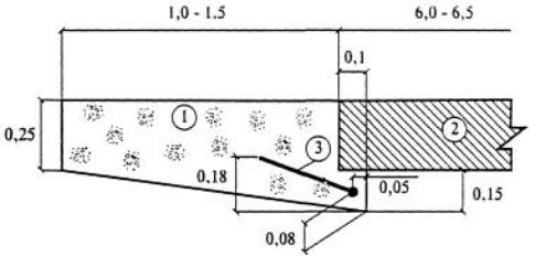
Fig. 9.1. Diagram of cement concrete blanket widening
1 – new concrete blanket; 2 – old concrete blanket, 3 – reinforcement.
New concrete blanket at the place of conjunction is thicker than an old one and has prominence which is under an old surface. So an old surface receives edge reinforcement due to the rest onto the lane of widening. Seam between new and old surfaces is filled with mastic in order to protect water penetration.
Shortcoming of this structure is technological complicity.
There is proposed to apply asphalt concrete of “A” and “B” type of the first trade, polymeric asphalt concrete and also reinforced asphalt concrete for reinforcement of road base.
For polymeric asphalt concrete mixes preparation polymeric bitumen bindings based on polymeric additives should be used.
Grained composition and physicalchemical properties of polymeric asphalt concrete mixes should meet the demands of State Standard 9128-2013 "Asphalt concrete mixes, road, aerodrome and asphalt concrete".
Control test of polymeric asphalt concrete properties in a surface should be conducted by water saturation, swelling, porosity of mineral composition and residual porosity and also by compaction ratio.
Materials for reinforcement of cement concrete surface
Special kinds of reinforced steel are applied for layer reinforcement:
–hot-rolled rod of a periodic profile of А-II class, diameter is from 20 up to
20mm;
–the same of the class A-III of diameter from 6 up to 20mm;
–exhaust hardened bar steel of periodic profile of A-IIв class of diameter from 10 up to 20mm;
–the same of the class А-IIIв of diameter from 6 up to 20mm.
For reinforcement of asphalt concrete mixes there are used metal and polumeric fibres. Metal fibres are the pieces of 20-40mm length, diameter 0,3- 0,6mm. Their content is limited by o,5-2%. But in order to avoid tires puncture these mixes should be placed in a bed or leveling course.
46
Polymeric fibres are applied both as separate pieces (5-40mm length, mix is prepared in asphalt concrete plant) and continuous filaments. In other case the treatment is done directly on a road bed when fibres are sprayed on dirt road (dosage is 80-120gr/m2).
9.2. a) reinforced layers from continuously reinforced concrete is arranged according to ВСН 4-75
Layers of reinforcement from continuously reinforced concrete are unlimited length and broken only before artificial structures. End sections of reinforced layers should be fixed with immovable supports of trench and pile type.
Layer thickness is determined with calculation and can be 10-12cm. Longitudinal seams in dependence on the cross reinforcement are in 3,75m as
false type or in 5,5m as filleted joint 50 см.
Continuity of reinforcement is provided with rods lap in cross and longitudinal directions. Lap length is not less than 30-35d in longitudinal direction; in cross direction it is 25d (where d is a rod diameter) and in all cases it is not less than 250mm. Cross joints of adjacent nets are to be placed at random with a step not less than 50cm.
End rests of trench type are made in the following way:
–cross silts are done in an old surface on concrete spurs width by perforator with compressor;
–cross tranches are made by excavator near cross joints;
–reinforced frameworks are placed in trenches;
–concrete mix is placed and consolidated;
–top surface of concrete spurs is finished.
Before reinforced layer concreting reinforcement in the form of flat nets or frameworks is placed on seats put on a bed. Seats can be made from reinforcement of any class or from concrete of the same concrete mix which is applied for reinforced layer arrangement.
Reinforced layers from continuous reinforced concrete can be applied also during road base of non-rigid type reconstruction.
From three methods of road base reinforcement with cement concrete surface reinforced layer from continuous reinforced concrete is in preference. In this case a layer of reinforcement has the properties close to the properties of the material of the existing surface, the more so the volumes and cost of the works of road base repair after its reinforcement will be minimal.
In practice cement concrete surface reinforcement is done by asphalt concrete layers placement at that structure, type and trade of asphalt concrete and work production technology is defined in dependence on technical road category and road climatic zone.
Preparatory operations are mainly directed for defects elimination in cement concrete surface:
– completely destroyed slabs are removed and chanced by new monolithic
ones;
47
–voids under the slabs and slopes damages are corrected by bed profiling (slabs are removed) or by sand or cement delivering under slabs;
–slabs edges and angles chips are removed by depositing of asphalt concrete mix (fine grained or sand) at layer thickness up to 6cm and cement concrete ones at the thickness of more than 6 cm;
–distortion of longitudinal and cross profiles are corrected by placement of leveling layer from and or fine grained asphalt concrete by asphalt spreading machine;
–seams of existing surface are restored and filled them up with hermetic
mastics;
Before leveling layer placement there is done pouring of hot bitumen (0.3-0.5
l/m2) or bitumen emulsion (0.6-0.8 l/m2).
Technology at cement concrete surface reinforcement with layers from asphalt concrete mixes with account of crack resistance can be completed by the following methods:
–by placement of thick layers during one pass (thickness of the layer is 1018cm in Russia; 14-26 abroad);
–use of asphalt concrete mixes based on polymeric bitumen binder;
–by reinforcement of asphalt concrete mixes with metal or polymeric fibres;
–by asphalt concrete reinforcement in zones of cement concrete surface ujoints with geomaterials;
–by arrangement of movement joints over the joints of existing cement concrete surface.
The most positive effect is achieved at complex application of one methods simultaneously.
Compaction is the most difficult process at placement of thick layers placement for pass so it is necessary to apply rollers with 15-20tone weight and increase the number of roller passes on the same track.
Reinforcement with geomaterials is implemented directly both on the asphalt concrete contact with cement concrete (in leveling layer) and in upper surface layers.
The width of placed material is 1,2-2,0 м over the joints of cement concrete surface.
The arrangement of movable joints allow excluding unsystematic cracks formation in asphalt concrete surface. Cross joints are over expansion joints and at their absence in 10-30m in dependence on average temperature of cold month. Before placement of asphalt concrete over joints ruberoid or bitumen felt is placed onto cement concrete in two layers on the width not less than 7 thicknesses of asphalt concrete layer.
Joint widths is 1,2-1,7cm, depth is not less than 1/3 of asphalt concrete thickness but not more than upper layer thickness at multilayered surface.
Joints are arranged with cutters in the completely compacted and cold asphalt concrete. Filling of joints with mastics are fulfilled before cold period coming and start of transport movement.
48
UNIT X
CULVERT RECONSTRUCTION AND LENGTHENING
10.1.Full reconstruction of culvert.
10.2.Lengthening of culver.
During road reconstruction in the case of increasing of subgrade widening and also at embankment height or at slop flattering culverts lengthening is necessary. There are two variants:
а) Full reconstruction of culverts if diagnostics and forecasting of culverts condition shows that existing pipe cannot operate perfectly until the next road reconstruction.
b) Pipe length change without reconstruction of exiting part if existing pipe condition can operate normally until the new reconstruction at perfect maintenance and repair.
These works are willingly to do during dry year period or in winter time in order to protect water flow affect running through culvert.
10.1. Full culvert reconstruction includes the processes which are analogical to new culvert construction
1.Before operation necessary road marks, rams and pointers are placed.
2.Development of existing road pavement in the boarders of future foundation pit and material removal by scarifiers and dump trucks
3.Trenching of foundation pit and old pipe digging out from soil up to the foundation foot level by excavator with drag shovel. Foundation pit foot should be wider than foundation of old pipe by 3 m from one side (for machine passing) and from other side by 1m (for workers’ movement).
Foundation pit slop should provide operation safety (usually not sleeper than.1:1). If Water can run through culvert during the process of its reconstruction foundation pit is widened and temporary bypass channel the width and depth of which should be designed is constructed.
4.Pipe disassembling with application of electric and pneumatic picks, motor crane, bulldozers. If curve blocks and pipe foundation does not have inadmissible defects they can be saved. If there are destructions curve blocks are moved outside foundation pits by bulldozer. Foundation material can be used for reinforcement of temporary bypass channel.
5.Levelling and compaction of foundation bottom by bulldozer, vibration rollers or plate vibrators. If necessary while leveling there is done foundation pit filling up with soil of the same type as local soil is. Ramp of vehicles driveway is constructed with upper pipe pipe with inclination of 100 ‰ (fig. 10.1).
49
Fig. 10.1. Assembly of radial blocks of one point culvert aqueduct:
1– trench excavated in existing widened subgrade entry into trench as ramp;
2 – ramp; 3 – placed radial pipes; 4 – motor crane; 5 – storage place of radial blocks; 6 – trench for head wall; 7 –cement solution; 8 – embankment slop
6.Foundation construction from sandy gravel or crushed stone mix.
7.Distribution of cement mortar and assembly of portal walls, blocks openers and curve blocks. Cement mortar is usually distributed by hands by layer of 10-15 cm. Pipes are assembled by motor crane (fig. 10.2).
Fig. 10.2. Assembly of two point pipe
1 – vehicle with delivered pipes links; 2 – automobile crane; 3 – radiating blocks; 4 – culvert aqueduct links.
8. Seams grout in between blocks of portal walls and openers, embedment and stopwater of joints.
Seams of portal walls and openers are caulked and filled up with cement mortar which is compacted with metal poking. Stopwater of seams is done with two layers of bituminized fibre and three layers of asbestos bitumen mastics (fig. 10.3).
50

Fig. 10.3. Filling of double point pipe pocket with asphalt concrete (a), pipe flashing (б)
1 – bunker with metal hose delivering cement concrete mixture for pockets filling; 2 – vehicle – dump truck delivering cement concrete mixture; 3 – binder distributer with hand bitumen distributor for hydraulic seal.
9.Foundation pit is filled with layerwise compaction by bulldozer beginning with side pockets where soil is compacted by mechanical compactor. Soil over pipe as also compacted up to the general dump thickness of o,5m in compacted condition. Thickness of every compacted layer in pockets and over the pipe while using mechanical compactors should be 0,10-0,12 m.
Higher than o,5 m thickness compaction is done by self-propelled vibration rollers. Thickness of every layer is 0,15m. Soil should have optimal moisture.
10.Clearing of supply and discharge channel reinforced with concrete slab and slop protection at end wall. Full reconstruction of rectangular culvert includes operations observed before with exception of assembly of curved blocks instead of which there is constructed monolithic foundation.
Big triangular reinforced concrete culverts are often concreted on place. Curbs are placed on prepared foundation, assemble and weld reinforced frame, concrete by crane and tub. Compaction is done by external vibrator through curb and pervibrators.
10.2.Lengthening of culvert for extension of operation volume is recommended to make from the side of outlet portal. That is why single side widening of subgrade and road pavement is predicted. In the case of constant water running through culvert there is arranged temporary outlet channel from bottom side by excavator with drug shovel and remove reinforce of conduit and slops. Soil slop removal is executed by excavator with drug shovel and at height of more than 3m it is done by excavator –dragline.
Culvert head walls, openers and portal walls are destructed by pick hummers and cranes locating on embankment. Foundation pit digging out for foundation of lengthened culvert is done by excavator with back shovel. All other operations are implemented analogical to the whole curvet reconstruction. Lengthened culvert part is filled up simultaneously with subgrade widening.
Data for determination works duration on culvert aqueducts building or reconstruction and content of specialized brigades is given in table 10.1-10.4.
51
References data
“Design characteristics for construction organization”.
|
Length of head reinforced pipes walls |
|
Table 10.1 |
|||||
|
|
|
||||||
Characteristics |
Pipes size |
|
|
|
|
|
|
|
|
|
|
Circular |
|
|
rectangular |
||
Pipes holes |
0,75 |
1 |
|
1,5 |
2 |
|
2-2,5 |
3-4 |
Length of two portals |
0,8 |
6,9 |
|
8,8 |
10,7 |
|
10,9 |
9,7 |
|
|
|
|
|
|
|
|
|
Table 10.2 Content of special brigades for construction of circular and rectangular pipes
names |
number of holes(size) |
|
|
|
|
|
1 |
1,5 |
2 |
2-2,5 |
3-4 |
Personal staff |
|
|
|
|
|
Drivers of road machunes |
4 |
4 |
4 |
5 |
6 |
road builders |
6 |
6 |
6 |
2 |
2 |
Assembler of structures |
- |
- |
- |
5 |
5 |
Machines and equipments |
|
|
|
|
|
Motor cranes of 6t |
1 |
1 |
- |
1 |
1 |
|
|
|
|
|
|
10 т |
- |
- |
1 |
- |
- |
Buldozers (on tractor of 95-110 h.f.) |
1 |
1 |
1 |
1 |
1 |
Roller on pneumatic tires |
1 |
1 |
1 |
1 |
1 |
Moving electric station (power of 4,5- |
1 |
1 |
1 |
1 |
1 |
9 kVt |
|
|
|
|
|
Electric vibrators (depth) |
3 |
3 |
3 |
3 |
3 |
Excavator of 0,3 м3 |
1 |
1 |
1 |
1 |
1 |
Moving bitumen barrel |
1 |
1 |
1 |
1 |
1 |
Electric compaction |
2 |
2 |
2 |
2 |
2 |
Table 10.3 Working hours of special brigades for reinforced concrete pipes construction
|
\Size of pipes hole |
Necessity in brigade operation, shifts |
|
|
m |
for 1 running meter |
for 2 portals |
|
1. Without base pipes |
|
|
|
0,75 |
0,06 |
0,68 |
|
1 |
0,06 |
4,20 |
|
2х1 |
0,13 |
5,8 |
|
3х1 |
0,20 |
7,3 |
|
1,25 |
0,07 |
4,9 |
|
2х1,25 |
0,14 |
6,4 |
|
3х1,25 |
0,21 |
5,7 |
|
1,5 |
0,09 |
5,7 |
|
2х1,5 |
0,18 |
7,9 |
|
3х1,5 |
0,27 |
12,5 |
1. |
ipes with base |
|
|
|
1 |
0,15 |
4,1 |
|
2х1 |
0,33 |
5,8 |
|
3х1 |
0,5 |
7,2 |
52
1,25 |
0,22 |
4,8 |
2х1,25 |
0,46 |
6,3 |
3х1,25 |
0,72 |
7,8 |
1,5 |
0,25 |
5,5 |
2х1,5 |
0,53 |
7,7 |
3х1,5 |
0,9 |
12,4 |
2 |
0,33 |
6,9 |
2х2 |
0,66 |
11 |
3х2 |
1,2 |
12,5 |
|
|
|
|
|
Table 10.4 |
|
Working hours for construction of rectangular pipes of prefabricated concrete |
||||||
Pipe hole, m |
Brigade work, shift |
|
|
|
|
|
|
per 1m of pipe |
|
for two end wall |
|
|
|
|
|
|
at prefabricated |
at |
monolithic |
|
|
|
base |
|
base |
|
|
2 |
0,32 |
|
5,8/2,84 |
6,08/2,98 |
|
|
2х2 |
0,47 |
|
7,5/4,74 |
8,04/5,08 |
|
|
2,5 |
0,36 |
|
6,3/4,7 |
8,12/6,06 |
|
|
2х2,5 |
0,57 |
|
8,56/5,32 |
9,4/5,84 |
|
|
3 |
0,45 |
|
6,48/4,83 |
8,35/6,23 |
|
|
2х3 |
0,63 |
|
7,88/5,87 |
8,65/6,45 |
|
|
4 |
0,57 |
|
6,88/5,13 |
8,87/6,62 |
|
|
2х4 |
0,85 |
|
9,16/6,83 |
10,16/7,58 |
|
|
UNIT XI
DEFECTS OF DAMAGES AND DESTRUCTION OF ROADBED
11.1.Causes of roadbed deformations.
11.2.Roadbed damages and deformations.
11.3.Roadbed slops damages.
11.4.Roadbed damages and destruction.
11.5.Roadbed foundation damages and destructions.
11.6.Roadbed damages and destructions caused by natural factors.
11.1.Technology of roadbed construction influences greatly on its stability. Breach of technology can causes deformation of roadbed as soil massive or local deformations of soil foundation.
Deformations can be caused by:
– deposition of soil not unusable for application without needed compaction, from heterogynous soils without observing the rules of their placing, without compliance with special requirements of dumping on weak soils
– embankment and cuts construction with deviation from design cross profiles;
53
–over wetting of roadbed soils because of non prepared drainage;
–reconstruction of roadbed with breach of rules of different soils placing, without reconstruction of drainage system, absence of solidity of existing roadbed and widened section.
11.2. Deformations, damages and destruction of roadbed can be divided into the following groups and kinds:
1.Damages and deformations of roadbed
Bed from sub base material – separately appeared depression in clayey grounds of roadbed.
Features: surface depression, underlayer course materials splashes onto surface, soils flow into ditches, buckling of embankment slops.
Causes: grounds bearing capacity decrease caused by moisture increase; water stagnation on roadbed surface caused by small cross slope or flattering.
Bed from materials of sub base –along road sometimes having longitudinal slope scoops in clayey grounds
Features: substances of surface in longitudinal direction, fluidization and splashes onto surface from sub base material, soils bulging into ditches, embankment slops bulging.
Causes: see “bed”
Bed from sub base material – isolated depression in clayey grounds of roadbed. Features: surface flashes, fluidization and splashes onto surface sub base
material, soils bulging into ditches embankment slops bulging.
Causes: grounds bearing capacity decrease caused by moisture increase; water stagnation on roadbed surface caused by small cross slope or flattering.
Spring frost heaving subsidence - carpet surfacing intensive local subsidence Features: local destructions, water heaving and then fluidized soil, slop
displacement and trenches damages.
Causes: abrupt decrease of bearing capacity of frost heaving soils at thaw Heaves – surfacing distortion as heaving humps
Features: formation of local knobs on surfacing in winter period
Causes: over wetting of sub base and soil of subbed ground in autumn period; use of heaving grounds for construction of sub bed, near location of ground waters.
Road sides destruction
Features: ruts and pits on edges, water stagnation; roadbed edge destruction; surfacing edge destruction.
Causes: insufficient roadbed ground compaction; bad edge reinforcement, small cross slop..
11.3. Roadbed slops damages
“Splits” – surface changing of forms of embankment slops and cuts by surface water or as a result of processes connecting with frost penetration or thaw of ground.
Features: in leakage on slops; presence of washed away places on surfacing and harden ground at slop base, washout of thawed ground
54
Causes: insufficient slop and road sides reinforcement; overwetting of grounds because of drainage units trouble and damage of protective course.
Slumping of cut slops – displacement of upper ground layers of 1-2m thickness with preservation of general slop stability.
Features: “slumping” differs from “splits” by complete displacing of soil layers, from sloping by small deep of soil digging.
Causes: big slop steepness, small compaction.
Creep of cut slop – replacement of soil downwards under the influence of gravity caused by total destruction of slop stability
Features: formation of longitudinal cracks on road sides; configuration change of slops and land surface in slop beds.
Causes: insufficient bearing capacity of ground embankment, high slop steepness, insufficient embankment soil consistency, difference in consistency and moisture of soil and slop part.
11.4. Damage and destruction of roadbed.
Spreading of the embankment-slow settlement with changing of initial roadbed configuration.
Features: embankment spreading – slow settlement with change of initial form of slops, edges, decrease of embankment height and increase of its width at foundation.
Causes: embankment construction from overwetting clayey soils with high content of frost clods, snow and ice penetration into embankment body, insufficient compaction, soil overwetting with surface water.
Sliding down of embankment or its part along inclined foundation – on hillside, inclined mineral bog bottom, along inclined frost foundation.
Features: surfacing replacement into direction of embankment movement, roadbed settlement, longitudinal cracks in embankment from lower side.
Causes: inaccurate preparation of hillside foundation of embankment during construction, slop of mineral bog bottom, presence of inclined and liquefied soil layers in embankment foundation, embankment location on inclined frost foundation.
Embankment settlement – without side replacement because of soil compaction from which it is constructed.
Features: surfacing and road sides settlement at non deforming embankment foundation; at longitudinal cracks on edges and slops.
Causes: insufficient soil during construction.
11.5. Damages and destruction of roadbed foundation
Soil creeps – replacement of soil which slide along underlayer to relief reduction side, without canting and falling.
Features: damages of soil massif and roadbed; formation of slop sides; change of roadbed configuration.
Causes: complex anti soil creep measures for surface and ground water withdrawal, slop and roadbed soil reinforcement.
55
Settlement of roadbed foundation (together with embankment) without side replacement
Features: settlement and deformation of edges and slops, cracks in them, subsiding and cracks at embankment foot, in some cases total subsiding of terrain at slop foot.
Causes: compaction of weak foundations, subsiding of weak foundation caused by drainage, rise of ground water in foundation of weakly compacted made grounds
Roadbed foundation settlement in zone of permafrost, drawdown and strongly reduced soils while thawing.
Features: change of road in longitudinal and cross direction, roadbed flash, local destruction of slops.
Causes: presence of ice saturated soils and underground water.
Карстовый провал - образование в земной коре пустот; karstic failure – interstices formation in land crust voids.
Features: presence fresh craters, cracks and other carster forms on land surface.
Causes: diluting action of water – atmospheric, river, underground. Suffocation failure – as a result of soil particles ejection from foundation by
underground water.
Features: accumulation of small soil particles on roadbed slops, in trenches, troughs; cracks on edges or slops, gradual settlement of roadbed and adjacent territory.
Causes: presence of soils in roadbed foundation. They contain particles washed out by ground and underground water.
Failures on bogs – with breaking of peat crust as result of unevenness of bog sediments compression under weight of roadbed and transport.
Features: the bulging mounds of soil foundation, longitudinal cracks on edges, increasing of roadbed settlement.
Causes: increasing of traffic volumes, soils overwetting, insufficient depth of weak soil (peat) removal in roadbed foundation, change of bog water regime.
Heaving of grounds in cut
Features: development of longitudinal cracks on edges, trench longitudinal profile distortion. Their profile compression splits and cracks on slops, distortion of longitudinal profile of cut in a whole.
Causes: presence of weak soil in road base. This soil is forced away outside.
11.6. Damages and destruction of roadbed caused by nature influence.
Trenches and ditches washing out by flood or rainfall waters with carrying over washed out material – first protective layers and then materials of slop and bottom.
Features: damages of bottom and slops of trenches and ditches; destruction of existing reinforcement; formation of ditches and water stagnation in them.
Causes: water running along ditch with speed exceeding designs one onto soils or reinforcement structures and also breach of these structure integrity.
56
Washing out of flooded slops and embankment body by streams, waves, ice floes damages – destruction of protection structures, soil carrying over.
Features: washing away of slop protection structures, formation of interstices under reinforcement slabs, appearance of ravines and caverns
Causes: poor made embankments slops reinforcement or application of consolidation structures non relevant to speed o running water, power of braking waves or floating of ice.
Banks washing out and caving – earth base by flow, waves, destruction by blocks of ice with soil carrying away from banks and slops of embankment and protection structures.
Features: banks destruction near embankments, dams (washing out – damages upper horizontal low water, undermining – lower horizontal low water).
Causes: absence of needed banks protection structures, regulation and breakwater structures or no sequences of these structures to local conditions, banks and embankment foundations made of light washed away soils.
Silting of ditches and ditches – progressive filling of their sections by soils come off from slops and neighboring territories and moved by flood and heavy shower waters.
Features: deposits of clay and sandy loam soils in cavities and ditches leading to their depth reducing
Causes: soil washing out on slops, adjacent territories and their drift into water drainage works; small speeds of water flow due to the small drainage system dip, different extraneous pieces falling into ditches and cavities.
SUM UP TEST
1. Road reconstruction – complex of actions directing to the road category change due to its improvement:
а) road performance indicators;
б) transport and operational characteristics of roads; c) transport and operational parameters of roadsю
2.Road reconstruction is necessary as a rule at traffic volume increase:
а) 1 time; b) 1,5 time;
c) 1,5 and more time.
3.Measures for road reconstruction are assigned based on:
а) visual inspection;
b)diagnostic;
c)assessment of traffic performance condition.
4. The most effective road condition and assignment of road reconstruction actions:
а) comparison method of technical parameters and characteristics;
57