


Structure of possible types of drainages is presented in fig. 5.6. Drainages laying depth is found by calculation but not less than 0,5 m.
a) |
b) |
c) |
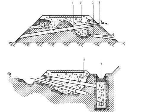
Fig. 5.6. Structure of trench drainage:
а) crushed stone – piped, b) without pipes; 1 – glue screen; 2 – polyethilen film; 4 – nonwolen synthetic material; 5 – crushed stone; 6 – dranage pipe
More often there is constructed shallow drainage. Drainage pipe is placed into hummocks along carriage way for water collection and drainage of roadbed. Shallow laying drainage arrangement is shown in fig. 5.7.
earth-deposit |
ditch, earth deposit of small height |
Fig. 5.7. Shallow laying drainage construction
32
Due to the relief water escape from near edge piped drainage is done with the help of cross escape onto terrain or into additional structures (collectors, drainages) from which discharge is done through outlet structures.
Draining of heaving sections is quite effecting if drains of well type are used. Passing with pneumodrills is the most productivity (fig. 5.8). Presence of inclination provides fast escape of free water caused by gravitation forces. Course sand or nonwolen geosynthetic material can be used as filler of such drains. Distance between drains is calculated according in dependence on time of draining and soil moisture of the rest part of section and usually it is 1, 5-2 m.
a)
Compressed air
b)Compressed air
Fig. 5.8. Application of pneumodrills for roadbed drainage construction:
а– embankment; б – cut
1– drainage well; 2 – pneumodrill; 3 – plant for wells filling with draining material; 4 – under ditches drainage; 5 – roadbed softened zone.
III group. Regulation of roadbed thermal regime. Regulation of roadbed
thermal regime is executed by frost protection and heat insulation layers.
Frost protection layers are road bed courses from granular materials such as crushed stone, sandy gravel mix, slag, not heaving soils and also soils reinforced with binding materials.
Heat isolation layers are roadbed courses from materials with more effective heat proofing properties than ordinal building materials have. Polymeric materials (foam plastic), light concrete with porous filler (haydite, crumbled foam plastic); local materials or production waste with addition of light fillers are belonged to such materials.
33

For protection of roadbed under road pavement against frost penetration the course from the edge sides should be 0,8-1,o m wider than carriageway. On the sections ends with heat insulating layer in longitudinal direction along the 3-5m length heat insulating layer thickness is steadily decreased in order to escape sharp transition from one structure to the other and protect possibility of cracks appearance in the place of conjunction.
Technology of heat insulating layer arrangement from materials reinforced with concrete or bitumen mineral materials differs from traditional one with light filler (ceramist, agloporite, pearlite). Layers compaction is done by light and average rollers.
Structure of road pavement with heat insulating layer is presented in fig. 5.9. а) road pavement structure with heat insulating layer from reinforced
materials and soils with light fillers;
б) the same with piped drains;
c) with frost protective layer from bitumen mineral mortar.
Fig. 5.9. Structure of road pavement with heat insulating layer
1 – pavement, 2 – base; 3 – reinforced lane; 4 – reinforced edge, 5 – sandy drainage layer; 6 – grass sowing; 7 – heat insulating layer; 8 – piped drain; 9 – discharge; 10 – frost proving layer.
34

UNIT VI
ROAD PAVEMENT WIDENING AND EDGES STRENGTHENING
6.1.Methods of road pavement widening and operation technology of road pavement construction on widening lane.
6.2.Widening lane choice requirements for road pavement structure.
6.3.Edge lane construction.
6.1. Method of carriage way widening is usually the same as method of roadbed widening. The more so way of road pavement widening depends on the necessity to strengthen road pavement.
|
|
Carriage way widening value |
Table 6.1 |
||
|
|
|
|
||
|
|
|
|
|
|
|
Road category |
Value of road widening, m |
|||
existing |
|
under reconstruction |
of carriage way |
of carriage way and |
|
|
|
|
|
edge lanes |
|
III |
|
II |
0.5 |
2.0 |
|
IV |
|
II |
1.5 |
3.0 |
|
IV |
|
III |
1.0 |
2.0 |
|
Following methods are possible:
1. One side widening of road pavement causes the necessity to construct leveling course and new surfacing on the whole width of carriage way.
At widening of road pavement by the value 2,0m and more into the direction of road roadbed should be cut off from the widening side (fig. 6.1).
a) |
|
|
|
|
|
b) |
|||||||||||
|
|
|
|
|
|
|
|
|
|
|
|
|
|
|
|
|
|
|
|
|
|
|
|
|
|
|
|
|
|
|
|
|
|
|
|
|
|
|
|
|
|
|
|
|
|
|
|
|
|
|
|
|
|
|
|
|
|
|
|
|
|
|
|
|
|
|
|
|
|
|
|
|
|
|
|
|
|
|
|
|
|
|
|
|
|
|
|
|
|
|
|
|
|
|
|
|
|
|
|
|
|
|
|
|
|
|
|
|
|
|
|
|
|
|
|
|
|
|
|
|
|
|
|
|
|
|
|
|
|
|
|
|
|
|
|
|
|
|
|
|
|
|
|
|
|
|
|
|
|
|
|
|
|
|
|
|
|
|
|
|
|
|
|
|
|
|
|
|
|
|
|
|
|
|
|
|
|
|
|
|
|
|
|
|
|
|
|
|
|
|
|
|
|
|
|
|
|
|
|
|
|
|
|
|
|
|
|
|
|
|
|
|
|
|
|
|
|
|
|
|
|
|
|
|
|
|
|
|
|
|
|
|
|
Fig. 6.1. Diagram of one sided asymmetric widening of road pavement and roadbed: а)carriageway widening more than 2m.;
b) carriageway widening up to 1,0-1,5 m
0-01 – road pavement old axes; I-I1 – new axes; 1 – top layer of new road surfacing; 2
– leveling course; 3 – top course of old surfacing and extension of its widening; 4 – lower course of old surfacing; 5 – base; 6 – additional layer of base; 7 – roadbed.
35