

1267
.pdfInduction motors are made with slip ranging from less than 5% up to 20%. A motor with a slip of 5% or less is known as a normal-slip motor. A normal-slip motor is sometimes referred to as a 'constant speed' motor because the speed changes very little from no-load to full-load conditions. A common four-pole motor with a synchronous speed of 1,800 rpm may have a no-load speed of 1,795 rpm and a full-load speed of 1,750 rpm. The rate-of-change of slip is approximately linear from 10% to 110% load, when all other factors such as temperature and voltage are held constant. Motors with slip over 5% are used for hard to start applications.
The direction of rotation of a poly-phase ac induction motor depends on the connection of the stator leads to the power lines. Interchanging any two input leads reverses rotation.
MAGNETIC MOTOR STARTERS
The magnetic motor starter is a magnetic contactor with an overload protection device. Unlike the fuse, the magnetic motor starter does not have to be replaced. It can be reset repeatedly.
|
The Motor Circuits |
|
|||
|
Larger |
current-demanding |
|||
|
motors use two circuits for |
||||
|
operation. One circuit is the |
||||
|
three-phase |
power |
circuit |
sup- |
|
|
plied from |
the |
distribution |
||
|
power panel. The other electri- |
||||
|
cal circuit is the control circuit. |
||||
The figure shows the magnetic motor starter and the power circuit from the |
|||||
distribution power panel. The heavy, dark |
lines provide the |
three-phase, |
high |
||
|
current-carrying po- |
||||
|
wer to the motor. |
||||
|
|
|
Inside the mag- |
||
|
netic |
motor starter, |
|||
|
directly |
under |
the |
||
|
coil, |
are |
three |
large |
|
|
main |
contact |
sets. |
||
|
These contacts are in |
||||
|
series with the power |
||||
|
panel A, B, and C |
||||
|
phase terminals |
and |
|||
|
the T1, T2, and T3 |
||||
|
motor terminals. As |
||||
Fig.1 |
long |
as |
these |
con- |
|
73

tacts are closed, current from the power distribution panel can operate the motor. This is one circuit.
The other circuit controls the three large contact sets explained above. The coil in Figure 1 actually moves the contacts. The figure shows the control circuit that the coil is actually in. M represents the coil in the figure.
The M coil is supplied single-phase power from the magnetic motor starters A and B phase terminals (also known as L1 and L2 terminals). The figure above shows two M coils: one in its true physical position in the magnetic motor starter and the other in the line diagram to explain its function electrically. There is actually only one M coil. The same applies to the NC overload contacts.
When the START button is pressed, a complete circuit from A phase through the M coil, through the NC overload contacts, to the B phase is completed in the control circuit. The M coil energizes and moves a bar, known as an armature, that is in physical contact with the three large power contacts in the motor's three-phase power circuit. The figure below illustrates this action.
The main power circuit contacts for the motor are held open by spring tension (see Figure view A). When the coil becomes energized, the magnetic attraction between the armature and the magnet overcomes spring tension, and the main contacts for the motor close (Figure view B). The motor now operates.
When the current to the motor is too great, the overload heaters get hot. The heaters are in series with the motor terminals and the main contacts for the
motor. The heaters directly control what happens to the NC overload contacts in the control circuit. When the heaters get hot enough, the overload contacts open, and the M coil de-energizes. The loss of the magnetic field allows spring pressure to open the three main contacts in series with the motor, and the motor stops operating. By de-energizing the one coil (M), all three sets of main contacts open. Detrimental single phasing is avoided.
A minor disadvantage of the thermal overload device is its need to cool off before being reset. The Figure shows a magnetic motor starter and the overload heater and NC overload contact section separately.
74
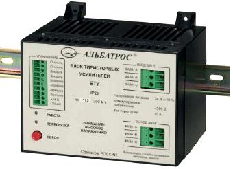
BTU THYRISTOR AMPLIFIER UNIT
1. Purpose
1.1. The BTU thyristor amplifier unit (hereinafter referred to as the "device") built around a solid-state semiconductor optronic three-phase relay is intended for switching of a single – or three-phase voltage applied to an electrical drive of an actuating mechanism. The "Open", "Close" and "Interlock" discrete inputs of the device, which perform con-
trol functions, are intended for operation with circuits consisting of "dry contacts" and do not call for additional power sources. The device has a discrete output to indicate current overload in the form of a normally open "dry contact". The device monitors current consumption of the electrical drive across phases B and C. In case of emergency or when the protection circuitry becomes deenergized, the power circuits are broken by an electromagnetic relay connected upstream of the semiconductor relay.
1.2. The device operating conditions and protection level.
1.2.1.Nominal values of climatic factors – according to GOST 15150 for the UKhL4 climatic version and atmosphere type II (industrial).
1.2.2.The device protection level is IP20 according to GOST 14254 (protection against getting of foreign solid bodies of more than 12.5 mm in diameter).
2. Specifications
2.1. The device characteristics are as follows:
–the number of discrete inputs to connect external control – three;
–the number of discrete outputs to indicate overloads in power circuits of the device – one;
–the number of switched phases – three;
–reversible phases – B and C.
2.2.Arranged on the device front panel are the OPERATION (green-color) and OVERLOAD (red-color) light-emitting diodes, the RESET button, as well as the CONTROL, 380 V INPUT and 380 V OUTPUT terminal connectors.
2.3.Electrical parameters and characteristics.
2.3.1. The device derives the supply from an external DC power source of (24±0.24) V.
75
2.3.2.Power consumption of the device via the +24 V circuit is not more than 180 mA.
2.3.3.Starting time – not more than 10 s.
2.3.4.As to its level of protection from electric shock, the device belongs to protection class I in compliance with the requirements of GOST 12.2.007.0.
2.3.5.The insulation voltage across the power circuits, control circuits and the +24 V circuit of the device withstands a test voltage of 1500 VAC 50 Hz without breakdown and surface flashover in normal climatic conditions.
2.3.6.Insulation resistance of the power circuits relative to the control circuits and the +24 V circuit is not less than 20 megohms in normal climatic conditions.
2.4. The device is rated for continuous operation.
2.5. The parameters of the device discrete inputs are as follows:
– open (closed) contacts of a system connected to the device correspond to the logical zero (unit) at the "Open", "Close" inputs;
– the logical zero voltage at the "Interlock" input is equal from 0 to 1 V;
– the open state of contacts of the system connected to the device corresponds to the logical unit at the "Interlock" input;
– the minimum duration of the logical unit or zero is equal to 0.1 s;
– the current value in the "Open", "Close" and "Interlock" circuits ranges from 15 to 24 mA.
2.6. The limit parameters of the device keys are as follows:
– a root-mean-square value of the power key switching voltage is not more than 420 V 50 Hz;
– an amplitude value of the power key switching current is not more than 10 A;
– the overload key switching voltage is not more than ±36 V;
– the overload key switching current is not more than 0.5 A.
2.7. The device ensures protection against overloads and short circuits in phases B and C.
2.8. The electrical drive supply circuit protection actuating current value is equal to (10±1.5) A.
2.9. Reliability.
2.9.1.Mean-cycles-between-failures of the device are not less than 40,000 h.
2.9.2.Service life of the device makes up 10 years.
3. Overall Dimensions and Mass
3.1.Overall dimensions of the device are given in Figure V.2.1.
3.2.The device mass is not more than 1.8 kg.
76

LEAD-ACID BATTERY
Lead-acid batteries, invented in 1859 by French physicist Gaston Planté, are the oldest type of galvanic cell battery. Despite having the second lowest energy-to-weight ratio (next to the nickel-iron battery) and a correspondingly low energy-to-volume ratio, their ability to supply high surge currents means that the cells maintain a relatively large power-to-weight ratio. This, along with their low cost, makes them ideal for use in cars, as they aptly provide the high current required by automobile starter motors. They are also used in vehicles such as forklifts, in which the low energy-to-weight ratio may in fact be considered a benefit since the battery can be used as a counterweight.
Lead-acid car batteries for a 12 volt system consist of six cells of 2.1 V nominal voltage. Each cell contains (in the charged state) electrodes of lead metal (Pb) and lead (IV) oxide (PbO2) in an electrolyte of about 37% (5.99 Molar) w/w sulfuric acid (H2SO4). In the discharged state both electrodes turn into lead(II) sulfate (PbSO4) and the electrolyte loses its dissolved sulfuric acid and becomes primarily water. Due to the freezing-point depression of water, as the battery discharges and the concentration of sulfuric acid decreases, the electrolyte (including the more modern gellified electrolyte of the gel battery) is more likely to freeze .
Many vendors sell chemical additives (solid compounds as well as liquid solutions) that supposedly reduce sulfate build up and improve battery condition when added to the electrolyte of a vented lead-acid battery. Such treatments are rarely, if ever, effective.
The following are general voltage ranges for six-cell lead-acid batteries:
-Open-circuit (quiescent) at full charge: 12.6 - 12.8 V
-Open-circuit at full discharge: 11.8 - 12.0 V
-Loaded at full discharge: 10.5 V
-Continuous-preservation (float) charging: 13 - 13.2 V
-Typical (daily) charging: 13.2 - 14.4 V
-Equalization charging (for flooded lead acids): 15 - 16 V
-Gassing threshold: 14.4 V
-After full charge the terminal voltage will drop quickly to 13.2 V and then slowly to 12.6 V.
The chemical reactions are (charged to discharged):
Anode (oxidation): Pb(s) SO42 (aq) PbSO4(s) 2e |
, |
o 0.356 V. |
|
Cathode (reduction): |
|
||
PbO2(s) SO42 (aq) 4H 2e |
PbSO4(s) 2H2O(l), |
o 1.685V. |
|
Because of the open cells with liquid electrolyte in most lead-acid batteries, overcharging with excessive charging voltages will generate oxygen and hydrogen gas by electrolysis of water, forming an extremely explosive mix. This
77
should be avoided. Caution must also be observed because of the extremely corrosive nature of sulfuric acid.
Construction of battery
Plates
It would be perfectly feasible to use simple sheet lead plates for the two electrodes. However such a construction would only produce around an amp for roughly postcard sized plates, and it would not produce such a current for more than a few minutes.
Planté realised that a plate construction was required that gave a much larger effective surface area. Planté's method of producing the plates has been largely unchanged.
A plate consists of a rectangular lead plate alloyed with a little antimony to improve the mechanical characteristics. The plate is in fact a grid with rectangular holes in it, the lead forming thin walls to the holes. The holes are filled with a mixture of red lead and 33% dilute sulphuric acid (Different manufacturers have modified the mixture). The paste is pressed into the holes in the plates which are slightly tapered on both sides to assist in retention of the paste. This paste remains porous and allows the acid to react with the lead inside the plate increasing the surface area many fold. It should be noted that at this stage the positive and negative plates are identical. Once dry the plates are then stacked together with suitable separators and inserted in the battery container. An odd number of plates is always used, with one more negative plate than positive. Each alternate plate is connected together. After the acid has been added to the cell, the cell is given its first forming charge. The positive plates gradually turn the chocolate brown colour of Lead Dioxide, and the negative turn the slate gray of 'spongy' lead. Such a cell is ready to be used.
Many modern manufacturers use pastes in the plates made directly from Lead Dioxide and Lead, thus avoiding the necessity to form the plates. Once acid is added, the cell is ready for use.
One of the problems with the plates in a lead-acid battery is that the plates change size as the battery charges and discharges, the plates increasing in size as the active material absorbs sulphate from the acid during discharge, and decreasing as they give up the sulphate during charging. This causes the plates to gradually shed the paste during their life. It is important that there is plenty of room underneath the plates to catch this shed material. If this material reaches the plates a shorted cell will occur.
Separators
Separators are used between the positive and negative plates of a lead acid battery to prevent short circuit through physical contact, Dendrites (‘treeing’) most and shredded active material. Separators cause some obstructions for the flow of ions i.e. electricity between the electrodes. Separators therefore must have the following characteristics:
78
-They must be porous high porosity gives a high rate of flow of ions.
-Pore size must be small enough to restrict the flow of colloid particles but not restrict the ions.
-They must be as thin as possible.
-Electrical resistance must be very high.
-They are a little larger than the plates to prevent material shorting the
plates.
To balance these criteria, the choice of separator shifted from wood to rubber to glass mat to cellulose based separators to sintered PVC separator to microporous PVC/polyethylene separator. An effective separator must meet a number of mechanical properties. Permeability, porosity, pore size distribution, specific surface area, mechanical design and strength, Electrical resistance, ionic conductivity, and chemical compatibility with the electrolyte. In service the separator must have good resistance to acid and oxidation.
In the battery service condition the following reaction can be shown:
PbO2 + 2H + SO4 = PbSO4 + H2O + ½ O2 ;
PbO2 + (oxidisable separator material) + H2SO4 = PbSO4 + (oxidized material).
Moreover, the battery service temperature can be as high as 70 to 80 degrees Celsius. The separator must be capable of resisting thermal degradation as far as possible.
Currently attempts are being made to develop alternatives to the lead-acid battery (particularly for automotive use) because of concerns about the environmental consequences of improper disposal of old batteries. Lead-acid battery recycling is one of the most successful recycling programs in the world, with over 97% of all battery lead recycled between 1997 and 2001. Effective Lead pollution control system is a necessity for sustainable environment. There is a continuous improvement in battery recycling plants and furnace designs for greater efficiencies. These recycling plants are ecology friendly as they follow all emission standards for lead smelters, but new methods should be devised or alternatives developed to the lead-acid battery so that lead pollution can be reduced to an essentially negligible amount.
Lead-acid batteries react less violently to fire exposure than nickelcadmium batteries, and so they are used in emergency lighting in case of power failure.
HOW THE FORD ESCAPE HYBRID WORKS
by Edward Grabianowski
Hybrid vehicles offer the best fuel economy of any car on the market by combining an efficient gasoline engine with an electric motor and batteries that are constantly recharged. Until 2005, most hybrid cars were small, and they
79
didn't have much horsepower or cargo space. The Ford Escape Hybrid changes all that. The Escape Hybrid is an SUV that gets up to 36 miles per gallon. That may not be as ultra-efficient as some hybrids, but it definitely saves the average family of four a lot of money at the gas pump.
In this article, we'll learn about Ford's brand new, patented hybrid powertrain, take a look at the Escape Hybrid's performance and find out why this car could be a major breakthrough for hybrids in the automotive marketplace.
A hybrid car is one that attempts to incorporate the strengths of both gasolinefueled combustion engines and electric motors while eliminating many of the problems that plague cars that are only one or the other. For gasoline cars, these problems include noise, expensive fuel and polluting emissions. Batterypowered electric cars have always been held back by short battery life and the need to plug the car in to recharge it.
A hybrid car has a combustion engine and an electric motor that work together (either at the same time or separately, depending on the type of hybrid). A hybrid car never needs to be plugged in for a recharge - whenever you step on the brakes, some of that energy is stored in the batteries. If the batteries get really low, the car can just run on gas until the combustion engine recharges them.
Now, let's take a closer look at the nuts and bolts (and wires and batteries) that lie beneath the Escape Hybrid's hood.
All hybrid cars have two power sources - a gasoline engine and an electric motor. They can work together in different ways, however. In so-called "mild" hybrid designs, the gasoline engine is always running, and the electric motor simply augments it, adding a little extra horsepower here and there to save some fuel. But Ford developed a full hybrid system for the Escape.
In a full hybrid system, the gasoline engine and the electric motor can both operate separately, or they can run at the same time. The Escape's hybrid system operates in four phases:
Start/Stop When you turn the ignition key of the Escape Hybrid, the electric motor comes to life. The electric motor, in turn, starts the gasoline engine. The car then performs a series of checks to determine if it can switch to electric-only operation: It checks to see if the batteries are charged, if the operating temperatures are okay and if interior climate control settings are in the appropriate range (the air conditioning's maximum setting requires the gasoline engine to run). If everything checks out, the engine will then shut off, leaving the car running under electric-only power. This process only takes a second or two.
When you come to a stop in the Escape Hybrid, the gasoline engine actually shuts off. The car runs on electric-only while you're at a stoplight or waiting in line at the drive-thru. Ford put a lot of effort into making the gasoline
80
engine on-off cycles as smooth and seamless as possible, but testers reported a discernible shudder in the vehicle when the engine went on or off. This is common to all hybrid cars.
Electric Drive As the Escape Hybrid accelerates from a stop, it does so under electric power. Electric motors are good at generating torque at lower rpm ranges, so they're perfect for this purpose. At about 25 mph, the gasoline engine starts back up. If you're driving in heavy city traffic, you could go all day using only electric power. The electric motor and gasoline engine operate in tandem up to highway cruising speeds.
Regenerative Braking Whenever you apply the brakes on a car, the kinetic energy of the car's movement is dissipated as heat. In a hybrid car, the brakes take some of that energy and, using the electric motor as a generator, put power back into the batteries. This is why hybrids actually get better mileage in start/stop city driving than they do on open highways. Every red light recharges the batteries.
Electric Assisted Cruising At highway cruising speeds (roughly 50 to 70 mph or 80 to 110 kph), the gasoline engine does most of the work. It's most efficient at this speed range. But because the Escape Hybrid has a small, fourcylinder engine, it needs a little help when passing. When a speed boost is called for, the electric motor kicks in and adds its horsepower to that of the gasoline engine.
The Escape Hybrid (along with all other hybrid cars) doesn't have the usual transmission, with separate gears for the car to shift into and out of. Instead, the Escape uses an electronically controlled continuously variable transmission (eCVT). On-board computers set the gearing to the optimum setting for fuel efficiency, resulting in a 30 percent increase in efficiency over a conventional transmission, according to Ford engineers.
Escape Hybrid Specs.
To improve efficiency in the gasoline engine itself, Ford used a fourcylinder Atkinson-cycle engine in the hybrid version of the Escape. Atkinson engines are more fuel efficient than standard-cycle engines (known as Ottocycle engines) at the expense of horsepower.
The Escape Hybrid's 2.3-liter, aluminum, four-cylinder, dual overhead cam engine generates 133 horsepower at 6,000 rpm. The three-phase, permanentmagnet, synchronous electric motor adds 94 horsepower in the 3,000-5,000 rpm range. By itself, the gasoline engine can crank out 129 lb-ft of torque at 4,500 rpm. (For comparison, the four-cylinder engine in the non-hybrid Escape generates 153 hp at 5,800 rpm and 152 lb-ft of torque at 4,250 rpm.).
The AWD Escape Hybrid weighs in at 3,893 lbs (1,766 kg) the hybrid components add about 500 pounds (230 kg) to the Escape's weight. With a wheelbase of 103.1 inches (261.9 cm) and an 8-inch (20-cm) ground clearance,
81
it's a relatively compact SUV. The Escape rides on Continental ContiTrac EcoPlus tires (spare included). The fuel tank holds 15 gallons.
As a first attempt to create a practical hybrid SUV, the Ford Escape Hybrid is an excellent piece of engineering. It's definitely better for the environment and offers lower fuel costs than any other SUV on the market. Although it isn't as environmentally friendly as a Toyota Prius, rated at 60 mpg in the city and 51 mpg on the highway, it may be better for the planet in the long-term. By making a hybrid for the average family, which generally needs a bit of room to travel comfortably, Ford could be helping to put millions of hybrids in American garages within a decade.
LEAD ACID BATTERIES AND THE ENVIRONMENT
Environmental Benefits of the Lead-Acid Battery
By any measure, lead-acid batteries and the environment are one of the environmental success stories of our lifetime. More than 98 percent of all battery lead and plastic is recycled, making the lead-acid battery the recycled leader of all consumer products.
The life cycle of a lead-acid battery follows a continuous, closed loop. The typical new lead-acid battery is made with 60 to 80 percent recycled lead and plastic. When a spent battery is collected and returned to a permitted recycler, its lead and plastic are reclaimed and directed to new battery manufacturing.
Lead-acid battery safety efforts by the battery industry have led to the adoption of battery recycling laws in 38 states while five others have disposal bans. What other industry works so hard to steward its product from the beginning of its service life, through distribution, collection of old product, recycling and reclamation, and back to another service life? What other industry takes responsibility to meet stringent environmental regulations that protect the environment while providing a critical recycling service?
Air Filtration, Clean Water, Clean Air, Work Practices, Fugitive Emissions
More than 80 percent of lead produced in the United States is used in leadacid batteries. The battery industry takes pride in its advanced technology and common sense practices that dramatically reduce lead emissions from manufacturing and recycling facilities.
The battery industry is regulated by local, state, and federal agencies, which inspect manufacturing and recycling plants to verify that the companies are meeting standards.
82