

1267
.pdf10. Such instruments are called multimeters or universal instruments or multirange instruments.
10. Прочтите текст еще раз и ответьте на вопросы.
1.What must one determine for the measurement of a mass?
2.What is used for measuring temperature?
3.What indicating instruments are most convenient for every-day measurement?
4.What effect is employed for the production of such instruments?
5.What single principle is known to underlie all electromagnetic instruments?
6.How does the magnetic needle turn in the moving needle instrumens?
7.How does it turn in the moving coil instruments?
8.How does the iron move in the soft iron instruments?
11. Прочтите текст и, основываясь на его содержании, заполните таблицу.
|
construction |
operation |
usage |
|
|
principle |
|
ammeters |
|
|
|
voltmeters |
|
|
|
|
AMMETERS AND VOLTMETERS |
|
|
The action of almost all the types of measuring instruments is such that an electric current as distinct from an electric potential, is primarily responsible for the ultimate mechanical force required to produce movements of the instrument pointer. This has an exceedingly important influence on the practical forms of ammeters and voltmeters. By this is meant, that all, except the electrostatic type of instrument, are fundamentally current-measuring devices. They are fundamentally ammeters. Consequently, most voltmeters are merely ammeters so designed as to measure small values of current directly proportional to the voltages to be measured. It is only natural, therefore, that voltmeters and ammeters should be classified together.
Ammeters, which are connected in series in the circuit carrying the current to be measured, are of low electrical resistance, this being essential in order that they cause only a small drop of voltage in the circuit being tested, and accordingly absorb a minimum power from it.
63
Voltmeters are connected across, that is, in parallel with, the circuit points where the voltage is to be measured, and are of high resistance, in this case sufficiently high so that the current flowing in the voltmeter, and the power absorbed from the circuit, are small as possible.
The principle upon which both of these devices operate is essentially the same as that of the electric motor, differing from the motor, however, in the delicateness of their construction and the restrained motion of the rotating armature.
A coil of fine copper wire is so mounted between the two poles of a permanent magnet that its rotation is restrained by a hair spring. The farther the coil is turned from its equilibrium or zero position, the greater is the restoring force. To this coil is fastened a long pointer at the end of which is a fixed scale reading amperes if it is an ammeter or volts if it is a voltmeter. Upon increasing the current through the moving coil of an ammeter or voltmeter the resultant magnetic field between coil and magnet is distorted more and more. The resulting increase in force therefore turns the coil through a greater and greater angle, reaching a point where it is just balanced by the restoring force of hairspring.
Whenever an ammeter or voltmeter is connected to a circuit to measure electric current or potential difference, the ammeter must be connected in series and the voltmeter in parallel. The ammeter is so connected that all the electric current passes through it. To prevent a change in the electric current when making such an insertion, all ammeters must havea low resistance. Hence, most ammeters have a low resistance wire, called a shunt, connected across the armature coil.
A voltmeter, on the other hand, is connected across that part of the circuit for which a measurement of the potential difference is required. In order that the connection of a voltmeter to a circuit does not change the electric current in the circuit, the voltmeter must have a high resistanse. If the armature ciol does not have a large resistance on its own, additional resistance is added in series.
Very delicate ammeters are often used for measuring very small currents too. A meter whose scale is calibrated to read thousandths of an ampere is called milliammeter, one whose scale is calibrated in millionths of an ampere being known as microammeter or galvanometer.
64
12. Прочтите и выучите:
distinct – отличный, непохожий exceedingly – чрезвычайно, очень ammeter – амперметр consequently – следовательно therefore – следовательно, зато drop of voltage – спад напряжения sufficiently – достаточно
to mount – устанавливать, монтировать equilibrium – равновесие
restoring force – противодействующая сила
potential difference – напряжение, разность потенциалов hairspring – волосковая пружина
13.Переработайте текст, заменив формы времени Present на формы времени Past.
14.Переведите предложения на английский язык.
1. Амперметры, в отличие от вольтметров, соединяются последовательно. 2. В измерительных приборах именно электрический ток обусловливает, в первую очередь, возникновение механической силы. Последняя, в свою очередь, вызывает движение стрелки прибора. 3. Большинство вольтметров – это, по сути, амперметры, предназначенные для измерения малых токов, прямо пропорциональных измеряемым напряжениям. Этим объясняется то, что они обычно находятся в одном классе измерительных устройств.
15. Составьте план текстов “Electrical measuring instruments” и “Ammeters and voltmeters”. Пользуясь ответами на вопросы упражнения 10 и данными таблицы упражнения 11, подготовьте рассказ об электроизмерительных приборах.
65
ТЕКСТЫ ДЛЯ ДОПОЛНИТЕЛЬНОГО ЧТЕНИЯ, ПЕРЕВОДА И РЕФЕРИРОВАНИЯ
ADJUSTABLE SPEED DRIVE SYSTEMS
Commercial and industrial firms today use adjustable-speed drive (ASD) systems for a variety of applications. Most common of these include standard pumps, fans, and blowers. Newer applications include hoists and cranes, conveyors, machine tools, film lines, extruders, and textile-fiber spinning machines.
Many applications have unique demands and characteristics. Drive vendors have responded to this demand by producing a variety of drives. The combination of the many types of drives available and the abundance of applications has made the selection of the optimum drive for a given application a challenge.
New generation ASDs have evolved with advancements in solid-state electronics. ASDs can now be applied to ac motors regardless of motor horsepower or location within a facility and can be used to drive almost all types of motorized equipment, from a small fan to the largest extruder or machine tool. Commercial and industrial facilities can expect to dramatically reduce both energy consumption and operating and maintenance costs while offering improved operating conditions by using new generation electronic ASDs. The latest generation of ASDs allows ac induction motors to be just as controllable and efficient as their dc counterparts were.
Historically a variety of terms have been used to describe a system that permits a mechanical load to be driven at user-selected speeds. These terms include, but are not limited to:
Variable-Spee Drive Variable-Frequency Drive Adjustable-Frequency Drive Adjustable-Speed Drive.
The term variable implies a change that may or may not be under the control of the user. Adjustable is the preferred term since this refers to a change directly under control of the user. The term frequency can only be applied to drives with an ac output, while the term speed is preferred since this includes both ac and dc drives. Thus, the term most commonly accepted is AdjustableSpeed Drive (ASD).
BASIC ASD COMPONENTS
Most ASD units consist of three basic parts. A rectifier that converts the fixed frequency ac input voltage to dc. An inverter that switches the rectified dc voltage to an adjustable frequency ac output voltage. (The inverter may also control output current flow, if desired.) The dc link connects the rectifier to the
66
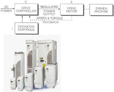
inverter. A set of controls directs the rectifier and inverter to produce the desired ac frequency and voltage to meet the needs of the ASD system at any moment in time.
The advantages of ASDs do not stop with saving energy and improving control. ASD technology can now be applied to manufacturing equipment previously considered too expensive or uneconomical. Such applications are often unique to a particular industry and its equipment, or even to a particular facility. Cost benefits, such as those obtained from improved quality, may be desirable for each application.
TRANSFORMERS
It is undoubtedly true that the principle of transformer action and the practical application of
this principle in connection with the construction of transformers and induction-type motors are responsible for the widespread use of alternating current as a primary source of electrical energy. The transformer is a simple, efficient, and comparatively inexpensive device used primarily in a-c circuits for the purpose of changing the voltage from one value to another. There are no moving parts in the transformer, which means that mechanical losses, always
present and responsible for much of the heating of rotating and reciprocating machines, are entirely absent. Actually, a transformer is a device that transfers electrical energy from one electric circuit to another without a change of frequency. This energy transfer usually takes place with a voltage change, although the latter is not always necessary or even desirable. The electric circuits being insulated from each other, as they are in most transformers, they are conventional and are generally referred to as transformers. In some special cases, the electric circuits are joined together, in which case the device is referred to as an autotransformer. The electric transformer winding being connected to the source of supply is called the primary, the winding that feeds the load being known as the secondary. Some transformers are designed to raise the primary voltage to a higher value, in which case they are known as step-up transformers; others are constructed to reduce the primary voltage to a lower value, in which case they are called step-down transformers. In step-up transformers the current on the secondary side is lowered in the same ratio as the voltage is raised, in stepdown transformers the current on the secondary side being raised in the same
67
ratio as the voltage is lowered. Transformers have many applications in a-c circuits that require both the raising and lowering of the primary voltage as well as the lowering and raising of the primary current. When used in groups in poly phase circuits, they are especially valuable in performing many im portant functions, one of which, apart from its voltage-changing use, is to change the number of phases from two to three, three to two, three to six, or several other combinations.
TYPES AND CHARACTERISTICS OF ALTERNATING
CURRENT MOTORS
Only three general types of d-c motor are found in practice, a comparatively large number of different constructions being available for use in a-c systems. The reasons for this situation is that each type of a-c motor is confined to narrower operating characteristics, especially with regard to such important matters as torque, overload capacity, speed variation, speed control, and starting procedures. Furthermore, a-c motors must be constructed for operation on single-phase service or polyphase (either twoor three-phase) service; in one type of construction they must perform satisfactorily on d-c service as well as on single-phase alternating current.
Classification of Single-Phase Motors. Single-phase motors generally have low horsepower ratings and are used to operate mechanical devices and machines requiring a comparatively small amount of power. Their greatest fields of application are in the fractional-horsepower range, that is, below 1 hp. Motors larger than the latter, up to perhaps 10 hp, are sometimes used on farms and in small shops and factories where polyphase power is not available. Polyphase motors generally have better operating characteristics than single-phase machines and cost less per horsepower, so that it is usually true that single-phase motors are used in the larger sizes only because of twoor three-phase service not being available.
In the single-phase classification may be listed the following types of motors: shaded-pole, reluctance, split-phase (with or without capacitor starting), repulsion, repulsion-start, repulsion-induction, series (a-c only or universal), and synchronous.
Shaded-pole and reluctance motors are built in very small sizes from about 1/500 to 1/6 hp; they are cheap to construct, have low starting torque, little overload capacity, and low efficiency and may be speed-controlled.
Standard split-phase motors are manufactured in sizes up to 3/4 hp; they are comparatively low in cost, have fair starting torque, not much overload capacity, and fair efficiency, and operate at nearly constant speed. Split-phase motors equipped with capacitors have high starting torque and may or may not be arranged to continue to run with a capacitor. Their
68
capacitor being used only during the starting period, they are called capacitor-start split-phase motors; two values of capacitor being provided, one for starting and another for running, they are referred to as two-value capacitor motors. However, whether or not these motors are provided with capacitors, they are all, nevertheless, split-phase motors.
Series motors are usually constructed for service on direct or alternating current up to 60 cycles, in which case they are called universal motors. When properly designed, they will operate with complete satisfaction on direct or alternating current, developing high starting torque, having excellent overload capacity and good efficiency, and permitting the speed to be controlled over very wide limits. Such motors are not as trouble-free as those described above (shaded-pole, reluctance, and split-phase types), because they have the usual commutator and brushes and their, accompanying commutation problems.
Synchronous motors, as the name implies, operate at synchronous speed, that is, a definite, constant speed determined only by the frequency of the supply and the number of poles on the machine. They have very little starting torque, practically no overload capacity, and are quite inefficient; they have, however, the one important characteristic possessed by none of the motors previously discussed, that is, absolute constancy of speed, a requirement that is very important for timing devices.
Classification of Polyphase Motors. Polyphase motors, that is, machines served with twoor three-phase power, may be classified as follows: induction (squirrel-cage or wound-rotor types), commutator, or synchronous.
Squirrel-cage induction motors are widely used because of their having, generally speaking, desirable all-purpose characteristics. They are comparatively low in cost per horsepower, have good starting torque and overload capacity, are highly efficient, and are particularly rugged and trouble-free. These motors will operate in an atmosphere containing dirt, moisture, or corrosive or explosive fumes and can even be constructed to perform submerged in oil or water. They are, practically speaking, constantspeed motors in the sense that change in load does not affect the speed by more than about 5 per cent. Such motors are, however, of a disadvantage when it becomes necessary to control the speed, because it is usually difficult or expensive, from the standpoint of additional equipment, to do so. When speed control becomes a necessary requirement of an application, the squirrel-cage rotor is often replaced by a wound rotor, its winding ends being connected to slip rings. Speed control is then accomplished by connecting a resistor controller to the brushes riding on the slip rings; the greater the resistance inserted, the lower the speed, and vice versa. Woundrotor motors, therefore, differ from squirrel-cage motors only by the
69
construction of the rotor, the stator of both types being exactly similar. In addition to its speed-control feature, the wound-rotor induction motor also develops considerably more starting torque. It does, however, have a lower full-load efficiency and a greater speed variation with load changes than does the squirrel-cage type of motor.
Synchronous motors for polyphase service are generally constructed with a stator core and winding similar to those used on induction motors (squirrel-cage or wound-rotor), but with a rotor consisting of a set of salient poles. The latter must be excited with direct current from a small exciter, that is, a self-excited shunt generator, mounted on an extension of the motor shaft or coming from a separate d-c source. Direct current is fed to the rotor field through brushes and slip rings. Since synchronous motors, as such, have no starting torque, it is always necessary to provide the rotor poles with a complete squirrel cage built into the pole faces. The motor can then be started in much the same way as are squirrel-cage induction machines; when nearly synchronous speed is reached, the d-c rotor field is excited, after which the motor continues to run at exactly synchronous speed. The outstanding advantages of this type of motor are (1) absolutely constant speed, determined only by the frequency of the supply and the number of rotor poles, and (2) the possibility of adjusting the motor power factor to any desirable value. Synchronous motors, when property designed, have good starting torque, overload capacity, and efficiency. They are more expensive than induction machines in the smallest sizes, but cost about as much as squirrel-cage or wound-rotor motors in ratings of more than 100 hp. As a rule, synchronous motors are used in applications requiring infrequent starting, where the load is substantially constant, and where high power factor or power-factor correction is desirable and profitable.
Although the speed of a wound-rotor motor can be changed over a wide range by the insertion of resistance in the rotor circuit, the efficiency of operation is very low at reduced speed. To offset this disadvantage, particularly in large motors where energy cost is important, special types of machines have been developed. There is a special motor construction that has wide speed-control possibilities In this motor, the stator is of the usual construction found in induction machines, but the rotor differs greatly from any of these already described. The latter has two windings, one on the top of the other, placed in deep slots. The primary winding, in the bottom of the slots, is connected to slip rings and is fed, through brushes, with polyphase alternating current. The other winding, on top of the primary and next to the rotor surface, is connected to a commutator. Finally, the stator winding, called the secondary, is connected to brushes riding on the commutator. Speed control is accomplished by shifting the brushes over the commutator, the method used being an ingenious mechanical lever construction
70
permitting the motion of all brushes simultaneously by the manual or motorcontrolled operation of a handle. Such motors are high in cost per horsepower but have good efficiency, starting torque, and overload capacity. They are used only when it is extremely important that the speed be varied over a wide range. An additional advantage of this motor is that power-factor adjustment is also possible.
AC INDUCTION MOTORS
AC induction motors are ideal for most industrial and commercial applications because of their simple construction and low number of parts, which reduce maintenance cost. Induction motors are frequently used for both constant-speed and adjustable speed drive (ASD) applications.
The two basic parts of an induction motor are the stationary stator located in the motor frame and the rotor that is free to rotate with the motor shaft. Today's motor design and construction are highly refined. For example, stator and rotor laminations have been designed to achieve maximum magnetic density with minimum core losses and heating. The basic simplicity of this design ensures high efficiency and makes them easily adaptable to a variety of shapes and enclosures.
A three-phase induction motor can best be understood by examining the three-phase voltage source that powers the motor. Three-phase currents flowing in the motor leads establish a rotating magnetic field in the stator coils. This magnetic field continuously pulsates across the air gap and into the rotor. As magnetic flux cuts across the rotor bars, a voltage is induced in them, much as a voltage is induced in the secondary winding of a transformer. Because the rotor bars are part of a closed circuit (including the end rings), a current begins to circulate in them. The rotor current in turn produces a magnetic field that interacts with the magnetic field of the stator. Since this field is rotating and magnetically interlocked with the rotor, the rotor is dragged around with the stator field.
When there is no mechanical load on the motor shaft (no-load condition), the rotor almost manages to keep up with the synchronous speed of the rotating magnetic field in the stator coils. Drag from bearing friction and air resistance prevents perfect synchronicity. As the load increases on the motor shaft, the actual speed of the rotor tends to fall further behind the speed of the rotating magnetic field in the stator. This difference in speed causes more magnetic lines to be cut, resulting in more torque being developed in the rotor and delivered to the shaft mechanical load. The rotor always turns at the exact speed necessary to produce the torque required to meet the load placed on the motor shaft at that moment in time. This is usually a dynamic situation, with the motor shaft speed constantly changing slightly to accommodate minor variations in load.
71
The rotor consists of copper or aluminum bars connected together at the ends with heavy rings. The construction is similar to that of a squirrel cage, a term often used to describe this type of ac induction motor.
The rotating magnetic field in the stator coils, in addition to inducing voltages in the rotor bars, also induces voltages in the stator and rotor cores. The voltages in these cores cause small currents, called eddy currents, to flow. The eddy currents serve no useful purpose and result in wasted power. To keep these currents to a minimum, the stator and rotor cores are made of thin steel discs called laminations.
These laminations are coated with insulating varnish and then edge welded together to form a core. This type of core construction substantially reduces eddy current losses, but does not entirely eliminate them.
By varying the design of the basic squirrel-cage motor, almost any characteristic of speed, torque, and voltage can be controlled by the designer. To standardize motor features the National Electrical Manufacturers Association (NEMA) has established standards for a number of motor features.
The speed of an ac induction motor depends on the frequency of the supply voltage and the number of poles for which the motor is wound. The term poles refers to the manner in which the stator coils are connected to the three incoming power leads to create the desired rotating magnetic field. Motors are always wound with an even number of poles. The higher the input frequency, the faster the motor runs. The more poles a motor has, the slower it runs at a given input frequency. The synchronous speed of an ac induction motor is the speed at which the stator magnetic flux rotates around the stator core at the air gap. At 60 Hz the following synchronous speeds are obtained:
Number |
of |
poles |
RPM |
2 |
|
|
3,600 |
4 |
|
|
1,800 |
6 |
|
|
1,200 |
8 |
|
|
900 |
10 |
|
|
720 |
12 |
|
|
600 |
Providing the motor is properly constructed, the output speed can be doubled for a given number of poles by running an ASD supplying the motor at an output frequency of 120 Hz. The actual speed of an induction motor rotor and shaft is always somewhat less than its synchronous speed. The difference between the synchronous and actual speed is called slip. If the rotor rotated as fast as the stator magnetic field, the rotor conductor bars would appear to be standing still with respect to the rotating field. There would be no voltage induced in the rotor bars and no current would be set up to produce torque.
72