

Mechanical Properties of Ceramics and Composites
.pdf270 |
Chapter 4 |
Figure 4.15 H vs. G -1/2 for ZnS. Vickers hardness data for CVD-ZnS [106–108] at 10 N ( 1 kg) and 100 N ( 10 kg) loads at 22°C. Note the distinct HV minima at G 20 m and 150 m respectively. (From Ref. 7, published with the permission of the Journal of the American Ceramic Society.)
m fit a Petch relation: HK 0.8 + 1.7G1/2 GPa (for G in m). It is not clear whether this data reflects an approach to an H minimum (i.e. at G or > 30 m) or the absence of one given the lower hardness and load of ZnSe and load used.
D.Occurrence and Character of Indent-Related Cracking Associated with H Minima
As shown earlier, H minima were generally observed with most harder, more refractory ceramics, and also some softer, less refractory materials. It was also shown that the extent of deviation of the H minima below the normal Petch dependence and the G values of the H minima, while both material dependent, both generally increased as the indent load increased. It was also noted that these H minima were associated with a maximum of the amount and complexity of cracking. This section documents this cracking and its association with H minima and shows that such minima occur when the indent and grain sizes are about the same; but this cracking can be seriously exacerbated by grain boundary phases enhancing intergranular fracture. Thus in contrast to a continuous in-

Grain Dependence of Indentation Hardness at 22°C |
271 |
crease in H with decreasing G, when such H minima and associated cracking occur, H values first decrease from single crystal values (i.e. at G = ∞) as G decreases until the indent size is on the same scale as the G and then increases as G decreases further, following a modified Petch relation (i.e. extrapolating to < single crystal H values at G = ∞).
First consider the G dependence of such minima, which is shown by both direct correlation with G values, and subsequent direct observations of the cracking associated with the H minima. Correlation with G data is provided by Table 4.2, which shows the ratio of the grain size at the H minima to the indent diagonal length (d) for materials having clear minima at one or more test loads. This shows that, while there is variation (discussed later), the H minima occur when G/d is 2–5 for Vickers and 1 for Knoop indents. (This trend is also indicated in many of the preceding H–G-1/2 plots, where an average value of d is given for some of the loads and materials.)
Next consider the character and occurrence of such cracking of interest here, which is not the commonly reported linear cracks extending out from one or more of the indent main diagonals often used for measuring toughness. The cracking of interest here is instead more localized around the indent, often of a spalling character, and in polycrystalline bodies it occurs extensively via intergranular fracture (Figs. 4.16–4.20). This localized cracking may exist mainly or exclusively by itself (e.g. Figs. 4.16B–D, 4.17D, 4.18BC, and 4.20), or in combination with the more commonly reported linear cracking (e.g. Figs 4.17D and 4.19B). Again, much of the cracking of interest is of a spalling character and is often intergranular, especially when the indent size is similar to G. As G becomes larger than the indent size, cracking again diminishes towards that of single crystals, where cracking is generally less than in large grain bodies, and is
TABLE 4.2 Grain Size/Indent Diagonal Ratios at Hardness Minimaa
|
|
HV |
|
|
|
HK |
|
|
|
|
|
|
|
|
|
Material |
100 gm |
500 gm |
1 kg |
|
100 gm |
500 gm |
|
|
|
|
|
|
|
|
|
Al2O3 |
|
50–100/23 |
|
50/24 |
50–100/68 |
|
|
BeO |
|
100/26 |
100/58 |
|
|
|
|
MgO |
20/14 |
25/43 |
|
15/39 |
30/100 |
|
|
ZrO2 |
50/12 |
50/29 |
|
|
|
|
|
MgAl2O4 |
50–200/11 |
50/26 |
20/37 |
|
|
100/74 |
|
TiB2 |
|
|
|
15/28 |
|
|
|
ZnS |
|
|
25/110 |
|
|
|
|
Average |
5 ± 4 |
2 ± 1 |
1 ± 0.9 |
1 ± 0.9 |
1 ± 0.5 |
|
|
aValues in m. Source: After Rice et al. [7], published with the permission of the Journal of the American Ceramic Society.

272 |
Chapter 4 |
Figure 4.16 Knoop indents in polycrystalline A12O3 at 500 gm with increasing G. Nominal G was (A) 6 m, (B) 11 m, (C) 3, 11 m (bimodal), and (D) 40 m. Note the general tendency for greater cracking, especially locally around the indent as G increases. (After Rice et al., [7], published with the permission of the
Journal of the American Ceramic Society.)
more ordered (i.e., some along preferred fracture on cleavage planes), hence providing less opportunities for spalling (e.g., Fig. 4.19). Similar indent-induced cracking in dense sintered Al2O3 (G 20–30 m) was shown by Lankford [109] at similar loads (e.g. 0.6 kg) at both room and modest elevated temperatures, and Anstis et al [110] reported such cracking in a dense Al2O3 with G 20 m (50 N load), but not finer G ( 3 m) or sapphire.
There are three intrinsic factors and one extrinsic factor that vary the above cracking. The first two and most distinct are test factors of load and indent type.

Grain Dependence of Indentation Hardness at 22°C |
273 |
Figure 4.17 Vickers indents (500 gm) in hot pressed polycrystalline A12O3 of varying G. (A) G 6 m; (B) G 40 m, (C) G 40 m, and (D) G 50 m. Note the general tendency for both more cracking and greater complexity of cracking, especially near the indent, as G increases. (From Ref. 7, published with the permission of the Journal of the American Ceramic Society.)
Thus such cracking and associated H minima, which probably first begin at some threshold load and then increase as indent load increases, so that while there can be considerable variation at a given load, the frequency and scope of this localized cracking clearly increased with increasing load (e.g., Figs. 4.18–4.20). The second factor is indent geometry, i.e. less cracking with Knoop vs. Vickers indents (e.g., Fig. 4.16 vs. 4.17) attributed to the long narrow character of the Knoop vs. the Vickers indenter (e.g. the length affecting the G value where cracking is a maximum, but the narrowness limiting the actual extent of cracking). The third factor, a body one, is the grain size (and also grain shape and orientation as noted in the next section). As shown by the H–G –1/2 plots and Table

274 |
Chapter 4 |
Figure 4.18 Vickers indents as a function of load in hot pressed and annealed MgO with G 100 m. Loads were (A) 100 gm, (B) 500 gm, and (C) 2 kg. Note the increase in extent and complexity of cracking, especially around the indent and its association with the grain structure with increased load. (From Ref. 7, published with the permission of the Journal of the American Ceramic Society.)
4.2, the H minima and associated cracking reach maxima at material and loaddependent G values. Clearly, in view of the G dependence, variations in G will vary the maxima in cracking, e.g. observations on a dense alumina with a bimodal G distribution (of 3 and 11 m) showed cracking more like the larger than the smaller G value (Fig. 4.16C), as might be expected by fracture being a weak link process and the larger G being closer to the G for most H minima in
Grain Dependence of Indentation Hardness at 22°C |
275 |
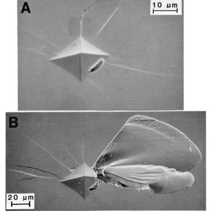
Figure 4.19 Vickers indents on {110} surfaces of stoichiometric MgA12O4 crystals. (A) 500 gm load, and (B) 2000 gm load. Note increased extent and complexity of cracking at the higher loads. (From Ref. 7, published with the permission of the Journal of the American Ceramic Society.)
most materials and tests. On the other hand, though opportunities to observe this have not apparently occurred, a mixture of grains larger than the G for maxima cracking would be expected to give cracking more consistent with the smaller G (but also impacted by its volume fraction).
The fourth and sporadic, but important extrinsic, body factor is the accumulation of additive or body constituents at grain boundaries when they significantly enhance intergranular fracture, thus enhancing grain spalling, in proportion to their amount, distribution, and effects on fracture. Thus contrast Fig. 4.18 (MgO hot pressed with no additives) and Fig. 4.20 (MgO hot pressed

276 |
Chapter 4 |
Figure 4.20 Vickers indents at various loads in MgO hot pressed (with LiF), but unannealed, having G 5 m. Loads were (A) 50 gm, (B) 100 gm, (C) 500 gm, and
(D) 1 kg. Note increasing grain boundary cracking as load increased. (From Ref. 7, published with the permission of the Journal of the American Ceramic Society.)
with LiF, but unannealed). MgAl2O4 hot pressed with similar additives also showed distinctly more local cracking and spalling vs. sintered material with no additive, despite much larger G in both bodies [7]. Such effects in both MgO and MgAl2O4 are consistent with reduced fracture energies/toughnesses for such bodies and increased intergranular fracture on a macro scale (Fig. 2.12).
A set of tests performed by Sperisen et al. [111], though limited, are very suggestive in their results and implications for future testing. They used a Vickers indenter mounted on the cross-head of a conventional testing machine so the rate of loading and unloading, as well as the loading level and time, could be independently controlled along with two supplemental testing aspects. The first was the use of acoustic emission detection during indentation, and second the use of a specimen holder allowing the surface to be indented to be covered with a liquid; in their case by oil or water for an inert versus active fluid. Using two dense, pure hot pressed alumina bodies (G 1 and 6 m) they observed effects
Grain Dependence of Indentation Hardness at 22°C |
277 |
of these parameters on both cracking from the indent corners (as for toughness measurements) and local spalling cracks, almost exclusively via intergranular fracture, in and around indents. While the cracking process was complex and somewhat variable, there were important trends, one of the most basic being that acoustic emission showed that most cracking occurred in three stages during loading, but some limited cracking occurred during two unloading stages. The nature and extent of these stages varied with G and the fluid environment of the indent. Indent cracks, e.g. for toughness measurement, which were mostly intergranular, appeared to initiate as Palmquist cracks that subsequently joined, with subsequent crack-to-indent-size ratios being the same for water and oil environments, reaching a constant level by loads of 15 N for G 1 m, but were still not fully independent of load for G 6 m 15 N load. The intergranular spall cracking was found to have no apparent threshold, i.e. observed at the lowest load tested ( 10-2 N), and to be substantially greater for the larger G and with water versus oil. Though limited and raising issues of the relative effects of the fluids as chemical species versus lubricants, such tests are suggestive of important complexities that have been almost totally neglected and deserve much more use and evaluation.
E.Effects of Grain Shape and Orientation, and Other Factors
There is very little data directly on the effects of preferred grain orientation on hardness, and as is unfortunately so common, very limited or no quantitative characterization of the degree and character of preferred orientation in specimens. This is a serious lack, since local or global orientation (or both ) can frequently be substantial and often, but not necessarily, occur with grain elongation. While either or both local and global orientation occur in vapor deposited (e.g. CVD) coatings or bodies [e.g. 68], some orientation can be much more common than is often noted in a variety of bodies, e.g. various sintered ones. However, there is substantial data on the effects of indent orientation on various single crystal surfaces that provides clear and detailed information on the limits of polycrystalline orientation effects on hardness. Such data is also a major demonstration of plastic deformation as the determining factor in hardness indentation of even the hardest materials. Thus, as noted in the introduction, the dependence of hardness on differing crystal surfaces and on indenter geometry and its orientation relative to crystal directions on a given crystallographic surface has been extensively and consistently shown to be due to varying activation of differing crystal slip systems [1–4]. There are substantially differing effects of different indenters, but there is a simple approximate interrelation between Knoop and Vickers [2] (the latter having less pronounced anisotropy). There are also the usual effects of load on hardness levels, and there may be some changes in the nature of the orientation dependence with differing loads due to some shifts in

278 |
Chapter 4 |
the balance of activation of differing slip systems. (There are also significant effects of temperature, e.g. Fig. 7.1, and differing effects of tensile versus compressive stresses [3] that can be pertinent to details of the relation of hardness and compressive strength, Chap. 5, Sect. II.B.) The orientation dependence of hardness on major, i.e. low index, crystal surfaces, is typically approximately a sinusoidal wave, often with some modifications, e.g. Fig. 4.21 (see also Fig. 7.1).
As reference for the extremes in the orientation dependence of hardness of polycrystalline ceramics, an outline of the single crystal orientation dependence is presented in Table 4.3 showing representative values of the maximum and minimum hardness and their ratio. Materials with extremely anisotropic structures (commonly materials with platy structures such as graphite, hexagonal BN, and mica) have extremes of hardness anisotropy and hence significant effects of preferred orientation on polycrystalline hardnesses (though these materials also commonly present challenges in obtaining good hardness values, especially with the loading direction parallel with the plane of the platy structure). Though not as extreme, other ceramics often have substantial hardness anisotropy, which often varies as much as or more for ceramics of various cubic versus those of noncubic structures (Table 4.3). Substantial other data is also available, e.g. for TiO2 [27], MgAl2O4 [47], SiC [63,66–69], other carbides [72,73,112], Si3N4 [69,113], SiO2 [69], MgO and LiF [114], and other oxides [36,115,116]. (Note that Ref. 113 is one of the few articles discussing composition–structure effects that may vary with details of grain/crystal growth that can be important in some materials such as SiC and Si3N4.)
These ceramic trends are similar to, but possibly less extreme than, those
Figure 4.21 Knoop hardness anisotropy on a (001) surface of CaF2 (A) and a (1100) surface of Al2O3 (B) (presumably at a 100 gm load) after Brookes and Burnand [3]. (Published with the permission of the American Society of Metals.)

Grain Dependence of Indentation Hardness at 22°C |
279 |
||||||
TABLE 4.3 Summary of Hardness Anisotropy of |
|
||||||
Some Ceramic Crystalsa |
|
|
|
|
|||
|
|
|
|
|
|
|
|
Material |
HH |
K |
(GPa) |
LH (GPa) |
HH/LH |
|
|
|
|
|
K |
|
|
|
|
(A) NaCl Cubic Structure |
|
|
|
|
|||
|
|
|
|
|
|
||
NaCl |
0.20 |
0.18 |
1.1 |
|
|
||
LiF |
0.97–.20 |
0.87–0.96 |
1.1–1.25 |
|
|||
MnS |
1.42–1.96 |
1.19–1.62 |
1.2 |
|
|
||
MnO |
2.87 |
2.52 |
1.14 |
|
|
||
MgO |
8.0 |
|
4.0 |
2.0 |
|
|
|
TaC |
16.5 |
|
15.0 |
1.1 |
|
|
|
ZrC |
22.5 |
|
19.8 |
1.14 |
|
|
|
HfC |
25.0 |
|
18.5 |
1.35 |
|
|
|
VC0.84 |
26.0 |
|
20.7 |
1.26 |
|
|
|
TiC0.80 |
23.0 |
|
20.0 |
1.15 |
|
|
|
TiC |
27.5 |
|
20.2 |
1.36 |
|
|
|
|
|
|
|
|
|||
(B) Other Cubic Structures |
|
|
|
|
|||
|
|
|
|
|
|
||
CaF2 |
1.78 |
1.57 |
1.13 |
|
|
||
Diamond |
96.0 |
|
69.0 |
1.39 |
|
|
|
|
|
|
|
|
|||
(C) Hexagonal Structures |
|
|
|
|
|||
|
|
|
|
|
|
|
|
Al2O3 |
18.0 |
|
14.0 |
1.29 |
|
|
|
Mo2C |
15.8 |
|
15.4 |
1.02 |
|
|
|
SiC |
29.5 |
|
20.3 |
1.45 |
|
|
|
aHH and LH are respectively the high and low, i.e. maximum and minimum, values for different Knoop indenter orientations on differing crystal surfaces; values in GPa. A range of values reflects two or more differing sets of data.
Source: Ref. 3.
for metals (Table 4.4). Thus single crystal anisotropy in hardness is a basic guide to the orientation dependence of hardness in polycrystalline bodies, but the grain size dependence (which may vary some with at least higher levels of preferred orientation) must be accounted for. An additional complication in the grain size dependence of ceramic hardness is the grain-related cracking that commonly occurs, as was extensively shown earlier. This is likely to be affected more (mainly reduced) by increasing preferred orientation, but no data or models are available for guidance. Grain shape can also be a factor in the orientation dependence of H, e.g. Chakraborty and Mukerji [69] showed that HV (100 gm) on prismatic planes doubled from 20 to 40 GPa as the aspect ratio of the grains (crystals) increased from 1 to 5 (beyond which H was constant). However,