

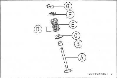
Closed Coil End

GE150303 S
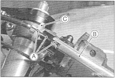
Valve Guide Removal
Remove:
Valve (see Valve Removal)
Oil Seal Spring Seat
Heat the area around the valve guide to 120 ~ 150"C (248 ~ 302 °F), and hammer lightly on the valve guide arbor [A] to remove the guide from the top of the head.
CAUTION _
Do not heat the cylinder head with a torch. This will warp the cylinder head. Soak the cylinder head in oil and heat the oil.
GE150305 S
Special Tool - Valve Guide Arbor, d>4: 57001-1273

http://moto.amoti.rtt/
|
Standard |
Service Limit |
Inlet |
0.03 ~ 0.12 mm |
0.29 mm |
|
(0.0012 - 0.0047 in.) |
(0.011 in.) |
Exhaust |
0.10 - 0.18 mm |
0.35 mm |
|
(0.0039 ~ 0.0071 in.) |
(0.014 in.) |
http://moto.amoti.rtt/

5-24
ENGINE TOP END
Valves
Valve
Seat Inspection
Remove
the valve (see Valve Removal).
Check
the valve seating surface [A] between the valve [B]
and
valve seat [C],
o
Measure the outside diameter [D] of the seating pattern
on
the valve seat.
If
the outside diameter is too large or too small, repair the
seat
(see Seat Repair).
Valve
Seating Surface Outside Diameter
Standard:
Inlet 26.4 ~ 26.6 mm (1.04 ~ 1.05 in.)
Exhaust 22.1
~ 22.3 mm (0.87 - 0.88 in.)
O
Measure the seat width [E] of the portion where there is
no
build-up carbon (white portion) of the valve seat with a
vernier
caliper.
Good
[F]
If
the width is too wide [G], too narrow [H] or uneven [J],
repair
the seat (see Valve Seat Repair).
Standard: Inlet,
Exhaust 0.5 ~ 1.0 mm
(0.02
- 0.04 in.)
®
0
Valve
Seat Repair
•
Repair
the valve seat with the valve seat cutters [A],
Valve Seating Surface Width


Valve Seat Cutter Holder, ({>4: 57001-1275 [B] Valve Seat Cutter Holder Bar: 57001-1128 [C] [For Inlet Valve Seat]
Valve Seat Cutter, 45° -<(>24: 57001-1113 Valve Seat Cutter, 32° - 4>25: 57001-1118 Valve Seat Cutter, 60° - <(>25: 57001-1328 [For Exhaust Valve Seat]
Valve Seat Cutter, 45° -<(>27.5: 57001-1114 Valve Seat Cutter, 32° - <(>28 : 57001-1119 Valve Seat Cutter, 60° -<(>27: 57001-1409 ★
GE150709S1
★ If the manufacturer’s instructions are not available, use the following procedure.

http://moto.amoti.rtt/
Valves
ENGINE
TOP END 5-25
Seat
Cutter Operation Care:
This
valve seat cutter is developed to grind the valve for repair.
Therefore the cutter must not be used for other purposes than seat
repair.
Do
not drop or shock the valve seat cutter, or the diamond particles
may fall off.
Do
not fail to apply engine oil to the valve seat cutter before
grinding the seat surface. Also wash off ground particles sticking
to the cutter with washing oil.
NOTE
O
Do
not use a wire brush to remove the metal particles
from
the cutter. It will take off the diamond particles.
Setting
the valve seat cutter holder in position, operate the cutter in one
hand. Do not apply too much force to the diamond portion.
NOTE
O
Prior
to grinding, apply engine oil to the cutter and during the
operation, wash off any ground particles sticking to the cutter with
washing oil.
After
use, wash it with washing oil and apply thin layer of engine oil
before storing.
Marks
Stamped on the Cutter:
The
marks stamped on the back of the cutter [A] represent the following.
60
’ Cutter angle [B]
37.5(f)
Outer diameter of cutter [C]
http://moto.amoti.rtt/

5-26
ENGINE TOP END
Valves
Operating
Procedures:
Clean
the seat area carefully.
Coat
the seat with machinist’s dye.
Fit
a 45" cutter into the holder and slide it into the
valve
guide.
Press
down lightly on the handle and turn it right or left.
Grind
the seating surface only until it is smooth.
[ CAUTION
Do
not grind the seat too much. Overgrinding will
reduce
valve clearance by sinking the valve into the
head.
If the valve sinks too far into the head, it will
be
impossible to adjust the clearance, and the cylin-
der
head must be replaced. *
★
Widened
Width [A] of engagement by machining with 45° cutter
Ground
Volume [B] by 32" cutter 32c
[C]
Correct
Width [D]
Ground
Volume [E] by 60" cutter 60" [F]
Measure
the outside diameter of the seating surface with a vernier caliper.
★ If
the outside diameter of the seating surface is too small, repeat the
45

Original Seating Surface [B]
NOTE
O Remove all pittings of flaws from 45" ground surface.
O After grinding with 45'“ cutter, apply thin coat of machinist’s dye to seating surface. This makes seating surface distinct and 32‘ and 60c grinding operation easier.
O When the valve guide is replaced, be sure to grind with 45r cutter for centering and good contact.

http://moto.amoti.ru/
ENGINE
TOP END 5-27
Valves
If
the outside diameter of the seating surface is too large,
make
the 32° grind described below.
If
the outside diameter [A] of the seating surface is within
the
specified range, measure the seat width as described
below.
Grind
the seat at a 32=
angle [B] until the seat O.D. is
within
the specified range.
oTo
make the 323
grind, fit a 32‘ cutter into the holder, and
slide
it into the valve guide.
OTurn
the holder one turn at a time while pressing down
very
lightly. Check the seat after each turn.
The
32° cutter removes material very quickly.
Check
the seat outside diameter frequently to
prevent
overgrinding. ★
O
After making the 32"’
grind, return to the seat O.D. measurement step above.
To
measure the seat width, use a vernier caliper to measure the
width of the 45:
angle portion of the seat at several places around the seat.
If
the seat width is too narrow, repeat the 45” grind until the seat
is slightly too wide, and then return to the seat O.D. measurement
step above.
If
the seat width is too wide, make the 60° [A] grind described
below.
If
the seat width is within the specified range, lap the valve to the
seat as described below.
★ Grind
the seat at a 60° angle until the seat width is within the
specified range.Caution
OTo make the 60= grind, fit 60 cutter into the holder, and slide it into the valve guide.
OTurn the holder, while pressing down lightly.
O After making the 60” grind, return to the seat width measurement step above.
Correct Width [B]


http://moto.amoti.ru/
5-28
ENGINE TOP END
Valves
Lap
the valve to the seat, once the seat width and O.D.
are
within the ranges specified above.
o
Put a little coarse grinding compound on the face of the
valve
in a number of places around the valve head.
oSpin
the valve against the seat until the grinding com-
pound
produces a smooth, matched surface on both the
seat
and the valve.
o
Repeat the process with a fine grinding compound.
Lapper
Valve
Seat
Valve
The
seating area should be marked about in the middle of the valve
face.
If
the seat area is not in the right place on the valve, check to be
sure the valve is the correct part. If it is, it may have been
refaced too much; replace it.
Be
sure to remove all grinding compound before assembly.
When
the engine is assembled, be sure to adjust the valve clearance (see
Engine Top End in the Periodic Maintenance chapter).
http://mofo.amofi.ru/

ENGINE
TOP END 5-29
Valves
http://moto.amoti.ru/
5-30
ENGINE TOP END
Cylinder,
Pistons
Cylinder
Removal
Remove:
Engine
(see Engine Removal/lnstallation chapter)
Cylinder
Head (see Cylinder Head Removal)
Remove
the cylinder.
Cylinder
Installation
NOTE
O
If
a new cylinder is used, use new piston ring.
Install
the pins [A] and new cylinder gasket [B].
Apply
engine oil to the cylinder bore.
Prepare
two auxiliary head bolts with their head cut.
Install
the two bolts [C] diagonally in the crankcase.
•
The
piston ring openings must be positioned as shown in
Top Ring [d] Oil Ring Expander
Second Ring [e] Lower Oil Ring Steel Rail
Upper Oil Ring Steel Rail [f] Hollow
Position the crankshaft so that all the piston heads are almost level.
Install the cylinder block [A],
Auxiliary Head Bolts [B]
Pistons [C]
Insert the piston rings with your thumbs.
Piston Removal
Remove the cylinder (see Cylinder Removal).
Place a clean cloth under the pistons and remove the piston pin snap ring [A] from the outside of each piston.


http://moto.amoti.rtt/
Cylinder,
Pistons
ENGINE
TOP END 5-31
•
Remove
the piston pins.
Special Tool - Piston Pin Puller Assembly: 57001-910 [A]
Carefully spread the ring opening with your thumbs and then push up on the opposite side of the ring [A] to remove
it.
Remove the 3-piece oil ring with your thumbs in the same manner.


Piston Installation
NOTE
O If a new piston is used, use new piston ring.
Install the piston with its marking hollow facing forward.
Fit a new piston pin snap ring into the side of the piston so that the ring opening [A] does not coincide with the slit [B] of the piston pin hole.
O When installing the piston pin snap ring, compress it only enough to install it and no more.
CAUTION
Do not reuse snap rings, as removal weakens and deforms them.
They could fall out and score the cylinder wall. * •
Install the oil ring expander [A] in the bottom piston ring groove so the ends [B] butt together.
• Install the oil ring steel rails, one above the expander and one below it.
O Spread the rail with your thumbs, but only enough to fit the rail over the piston.
O Release the rail into the bottom piston ring groove.
NOTE
O The oil ring rails have no “top” or “bottom”.

6E18002BS1 C

http://moto.amoti.rtt/
5-32
ENGINE TOP END
Cylinder,
Pistons
Do
not mix up the top and second ring.
Install
the top ring [A] so that the "R" mark [B] faces up.
Install
the second ring [C] so that the "RN" mark [D] faces up.
Cylinder
Wear
Since
there is a difference in cylinder wear in different di-
rections,
take a side-to-side and a front-to-back measure-
ment
at each of the two locations (total of four measure-
ments)
shown in the figure.
If
any of the cylinder inside diameter measurements ex-
ceeds
the service limit, replace the cylinder.
10
mm (0.39 in.)
60
mm (2.36 in.)
Cylinder
Inside Diameter
Standard:
ZX636 68.000
- 68.012 mm (2.677 - 2.678 in.)
ZX600 67.000
- 67.012 mm (2.637 - 2.638 in.)
Service
Limit:
ZX636 68.10
mm (2.68 in.)
ZX600 67.10
mm (2.64 in.)
GE1S0602S1
C
Piston
Wear
Measure
the outside diameter [A] of each piston 5 mm
(0.20
in.) [B] up from the bottom of the piston at a right
angle
to the direction of the piston pin.
If
the measurement is under service limit, replace the pis-
ton.
Piston
Diameter
Standard:
ZX636
ZX600
Service
Limit:
ZX636
ZX600
-
67.990 mm (2.676 - 2.677 in.)
~
66.990 mm (2.636 - 2.637 in.)
mm
(2.67 in.)
mm
(2.63 in.)
http://moto.amoti.ru/


Top |
ZX636 |
0.03 - 0.05 mm (0.0012 - 0.0020 in. |
|
ZX600 |
0.05 - 0.09 mm (0.0020 - 0.0035 in. |
Second |
|
0.03 - 0.07 mm (0.0012 ~ 0.0028 in. |
Service Limit |
|
|
Top |
ZX636 |
0.15 mm (0.0059 in.) |
|
ZX600 |
0.19 mm (0.0075 in.) |
Second |
|
0.17 mm (0.0067 in.) |
Piston Ring Groove |
Width |
|
• Measure the piston ring groove width. |
||
O
Use a vernier caliper at several points around the piston.
Piston
Ring/Groove Width Standard |
ZX636 |
0.82 - 0.84 mm (0.0322 - 0.0331 in.) |
|
|
ZX600 |
0.84 - 0.86 mm (0.0331 - 0.0339 in.) |
|
Second |
|
0.82 - 0.84 mm (0.323 ~ 0.0331 in.) |
|
Service Limit |
|
||
Top |
ZX636 |
0.92 mm (0.036 in.) |
|
|
ZX600 |
0.94 mm (0.037 in.) |
|
Second |
|
0.92 mm (0.036 in.) |
|

★
If
the width of any of the two grooves is wider than the service limit
at any point, replace the piston.
http://moto.amoti.rtt/
5-34
ENGINE TOP END
Cylinder,
Pistons
Piston
Ring Thickness
Measure
the piston ring thickness.
o
Use the micrometer to measure at several points around the ring.
Piston
Ring Thickness
Standard Service
Limit
Top 0.77
~ 0.79 mm 0.70 mm (0.028 in.)
(0.0303
- 0.0311 in.)
Second 0.77
~ 0.79 mm 0.70 mm (0.028 in.)
(0.0303
~ 0.0311 in.)
If
any of the measurements is less than the service limit on either of
the rings, replace all the rings.
NOTE
O
When
using new rings in
a used
piston, check for uneven groove wear. The rings should fit
perfectly parallel to the groove sides. If not, replace the piston.
Piston
Ring End Gap
Place
the piston ring [A] inside the cylinder, using the pis-
ton
to locate the ring squarely in place. Set it close to the
bottom
of the cylinder, where cylinder wear is low.
Measure
the gap [B] between the ends of the ring with a
thickness
gauge.
Piston
Ring End Gap
Standard Service
Limit
Top 0.12
~ 0.22 mm 0.5 mm (0.020 in.)
(0.0047
- 0.0087 in.)
Second 0.30
~ 0.45 mm 0.75 mm (0.031 in.)
(0.0118
- 0.0177 in.)
If
the end gap of either ring is greater than the service limit,
replace all the rings.
http://moto.amoti.rtt/

Throttle
Valve Holder
ENGINE
TOP END 5-35
Throttle
Valve Holder Installation
Be
sure to install the O-rings [A],
Tighten:
Torque
- Throttle Body Assembly Holder Bolts [B]: 12 N-m
(1.2
kgf rn, 104 in-lb)
http://moto.amoti.rtt/

5-36
ENGINE TOP END
To
avoid a serious burn, do not remove the mufflers when the engine is
still hot. Wait until the mufflers cool down.
Exhaust
Pipe Manifold Removal •
Remove:
Lower
Fairings (see Frame chapter) Muffler Body (see Muffler Body Removal)
Radiator [A] (see Cooling System chapter) Exhaust Pipe Manifold
Holder Nuts [B] Exhaust Pipe Manifold [C]
Exhaust
Pipe Manifold Installation
Replace
the exhaust pipe manifold gaskets with new ones.
Tighten:
Torque
- Exhaust Pipe Manifold Nut: 17 Nm (1.7 kgf-m, 12 ft-lb)
Exhaust
Pipe Clamp Bolt: 17 N m (1.7 kgf-m, 12 ft-lb)
Muffler
Body Bolt: 30 Nm (3.0 kgf-m, 22 ft-lb)
Thoroughly
warm up the engine, wait until the engine cools down, and retighten
all the bolts and nuts.
Muffler
Body Removal
Remove
the exhaust pipe manifold clamp bolt [A],
Remove
the muffler body mounting nut [B],
Pull
the muffler body backward.
Muffler
Body Installation
Replacing
the muffler pipe connection gasket with new one.
Tighten:
Torque
- Exhaust Pipe Manifold Clamp Bolt: 17 N-m (1.7 kgf-m, 12 ft-lb)
Muffler
Body Bolt: 30 N-m (3.0 kgf-m, 22 ft-lb)
Thoroughly
warm up the engine, wait until the engine cools down, and retighten
all the bolts and nuts.
http://mofo.amofi.ru/Muffler
A warning


Install the muffler body and exhaust pipe.
CLUTCH
6-1
Exploded
View 6-2
Specifications
6-4
Special
Tool and Sealant 6-5
Clutch
Lever and Cable 6-6
Lever
Free Play Inspection 6-6
Lever
Free Play Adjustment 6-6
Cable
Removal 6-6
Cable
Installation 6-6
Cable
Lubrication 6-6
Clutch
Lever Installation 6-6
Clutch
Cover 6-7
Clutch
Cover Removal 6-7
Clutch
Cover Installation 6-7
Release
Shaft Removal 6-7
Release
Shaft Installation 6-8
Clutch
6-9
Clutch
Removal 6-9
Clutch
Installation 6-11
Clutch
Plate Assembly Inspection 6-14
Clutch
Plate Assembly Adjustment 6-15
Clutch
Plate, Wear, Damage Inspection 6-15
Clutch
Plate Warp Inspection 6-15
Clutch
Spring Free Length Measurement 6-16
http://moto.amoti.ru/Clutch table of contents
6-2
CLUTCH
Exploded
View

No. |
Fastener |
Torque |
Remarks |
||||
N-m | kgf-m |
ft-lb |
||||||
1 |
Clutch lever holder bolts |
7.8 |
0.80 |
69 in-lb |
|
||
2 |
Clutch cover bolts |
12 |
1.2 |
104 in-lb |
L (2) |
||
3 |
Clutch hub nut |
130 |
13.5 |
98 |
|
||
4 |
Clutch spring bolts |
8.8 |
0.90 |
78 in-lb |
|
||
5 |
Clutch sub hub bolt |
25 |
2.5 |
18 |
L |
||
No. |
Parts |
Remarks |
|||||
6 |
Clutch spring holder STD |
Depth 15 mm |
|||||
|
OPTION |
Depth 14 mm |
|||||
|
OPTION |
Depth 13 mm |
|||||
CL:
Apply cable lubricant.
G:
Apply grease.
HG:
Apply high-temperature grease.
EO:
Apply engine oil.
L:
Apply a non-permanent locking agent. M: Apply molybdenum disulfide
grease.
R:
Replacement Parts
http://moto.amoti.rtt/
Item |
Standard |
Service Limit |
Clutch: Friction plate thickness Friction and steel plate warp Clutch spring free length ZX636 ZX600 Clutch plate assembly length ZX636 ZX600 |
2.72 ~ 2.88 mm (0.107 - 0.113 in.) 0.2 mm (0.008 in.) or less
39.85 mm (1.57 in.)
|
2.2 mm (0.087 in.) 0.3 mm (0.012 in.) 76.7 mm (3.02 in.) 38.5 mm (1.52 in.) |
http://mofo.amofi.rtt/
Special
Tool and Sealant
CLUTCH
6-5
Clutch
Holder: Kawasaki Bond (Silicone Sealant) :
57001-1243 56019-120
http://moto.amoti.rtt/

6-6
CLUTCH
Clutch
Lever and Cable
Lever
Free Play Inspection
O
Refer to the Clutch in the Periodic Maintenance chapter.
Lever
Free Play Adjustment
O
Refer to the Clutch in the Periodic Maintenance chapter.
Cable
Removal
Remove
the right lower fairing (see Frame chapter).
Slide
the dust cover [A] at the clutch cable lower end out
of
place.
Loosen
the nuts [B], and slide the lower end [C] of the
clutch
cable to give the cable plenty of play.
Screw
in the adjuster.
Line
up the slots [A] in the clutch lever [B], and adjuster
[C],
and then free the cable from the lever.
Free
the clutch inner cable tip from the clutch release
lever.
Push
the release lever toward the front of the motorcycle
and
tape the release lever to the clutch cover to prevent
the
release shaft from falling out.
Pull
the clutch cable out of the frame.
Cable
Installation
Run
the clutch cable correctly (see Appendix chapter).
Adjust
the clutch cable (see Clutch in the Periodic Maintenance
chapter).
Cable
Lubrication
O
Refer to the General Lubrication in the Periodic Maintenance
chapter.
Clutch
Lever Installation
Install
the clutch lever so that the mating surface [A] of
the
switch housing is aligned with the mating surface [B]
of
the clutch lever clamp.
Tighten:
Torque
- Clutch Lever Holder Bolts: 7.8 N-m (0.80 kgf-m, 69 in-lb)
http://moto.amoti.rtt/


Clutch
Cover
CLUTCH
6-7
Clutch
Cover Removal
Drain
the engine oil (see Cooling System in the Periodic
Maintenance
chapter).
Remove:
Right
Lower Fairing (see Frame chapter)
Clutch
Cable Lower End [A]
Clutch
Cover Mounting Bolts [B]
•
Turn
the release lever [A] toward the rear as shown, and
[C] about 90°
Clutch Cover Installation
Apply silicone sealant to the area [A] where the mating surface of the crankcase touches the clutch cover gasket. Sealant - Kawasaki Bond (Silicone Sealant): 56019-120
Replace the cover gasket with a new one.
Apply a non-permanent locking agent to the threads of the two clutch cover bolts [B],
Tighten the cover bolts.
Torque - Clutch Cover Bolts: 12 N m (1.2 kgf-m, 104 in-lb)

Release Shaft Removal
CAUTION ~
Do not remove the clutch release lever and shaft assembly unless it is absolutely necessary. If removed, the oil seal replacement may be required. * •
Remove the clutch cover (see Clutch Cover Removal).
• Pull the lever and shaft assembly straight out of the clutch cover.
http://moto.amoti.ru/
6-8
CLUTCH
Clutch
Cover
Release
Shaft Installation
Apply
high-temperature grease to the oil seal lips on the upper ridge of
the clutch cover.
Apply
oil to the bearing in the hole of the clutch cover.
Insert
the release shaft straight into the upper hole of the clutch cover.
CAUTION ~
•
When
inserting the release shaft, be careful not to remove the spring of
the oil seal.
• Apply
molybdenum disulfide grease to the pusher-holding portion on the
release shaft.
http://moto.amoti.ru/
Clutch
CLUTCH
6-9
Clutch
Removal
Drain
the engine oil (see Engine Lubrication System in
the
Periodic Maintenance chapter).
Remove:
Right
Lower Fairing (see Frame chapter)
Clutch
Cover (see Clutch Cover Removal)
Clutch
Spring Bolts [A]
Clutch
Spring Holders
Clutch
Springs
Clutch
Spring Plate [B] (with thrust bearing and pusher
[C],
spring and washer)
Friction
Plates, Steel Plates
Spring,
Spring Seat (ZX636 only)
Sub
Clutch Hub Bolts [A] (ZX600 only)
Clutch
Hub Nut [B]
O
Holding the (sub) clutch hub [C], remove the nut.
Special
Tool - Clutch Holder: 57001-1243 [D]
ZX636:
Remove:
Washer
Clutch
Hub
ZX600:
Remove:
Torque
Limiter Springs [E]
Collar
Sub
Clutch Hub
Clutch
Hub
Spacer
http://moto.amoti.rtt/

6-10
CLUTCH
Clutch
Using
the two 4 mm screws [A], pull out the sleeve [B],
needle
bearing [C] and clutch housing [D].
Remove
the spacer.
http://moto.amoti.rtt/
Clutch
CLUTCH
6-11
Clutch
Installation
Inspect
the clutch plate assembly length (see Clutch Plate
Assembly
Inspection).
Install
the following parts on the drive shaft.
Spacer
Sleeve
Needle
Bearing
Clutch
Housing
Spacer
Clutch
Hub
Washer
Nut
Sub
Clutch Hub
Collar
Torque
Limiter Springs
http://moto.amoti.rtt/


6-12
CLUTCH
Clutch
o
Install the spacer [A] so that the stepped side [B] faces inward.
ZX636:
O
Install the washer [A] so that the OUT SIDE [B] mark faces outward.
ZX600:
o
Install the collar [A] so that the groove [B] faces outward.
ZX600:
Pile
up the four torque limiter springs [A] so that the spring tongues
[B] does not faces same direction in the sub clutch hub [C].
Apply
a non-permanent locking agent to the threads of sub clutch hub
bolts.
Tighten:
Torque
- Sub Clutch Hub Bolts: 25 Nm (2.5 kgf-m, 18 ft-lb)
O
Replace the clutch hub nut with a new one.
O
Holding the clutch hub, tighten the clutch hub nut. Special
Tool - Clutch Holder: 57001-1243 Torque - Clutch Hub Nut: 130 N m
(13.5 kgf-m, 98 ft-lb)
http://moto.amoti.ru/

Clutch
CLUTCH
6-13
ZX636:
•
Install
the spring seat [A] and spring [B] as shown. [C] Clutch Hub
• Install the friction plates and steel plates, starting with a friction plate and alternating them.
CAUTION ~
If new dry friction plates and steel plates are installed, apply engine oil to the surfaces of each plate to avoid clutch plate seizure. * •
o Install the last friction plate [A] fitting the tangs in the grooves in the housing as shown.


ZX636:
• Apply molybdenum disulfide grease to the pusher end [A] and install the bearing [B], pusher [C] spring [D] and washer [E] in the clutch spring plate [F].
ZX600:
• Apply molybdenum disulfide grease to the pusher end [A] and install the shim [B], bearing [C], pusher [D] and spring
in the clutch spring plate [F],


• Install the clutch spring plate, spring and spring holders, and tighten the clutch spring bolts.
Torque - Clutch Spring Bolts: 8.8 N-m (0.90 kgf-m, 78 in-lb)
Install the clutch cover (see Clutch Cover Installation).
http://moto.amoti.ru/
6-14
CLUTCH
Clutch
Clutch
Plate Assembly Inspection
Inspect
the friction plate thickness (see Clutch Plate,
Wear,
Damage Inspection).
Measure
the length [A] of the clutch plate assembly as
shown.
ZX636:
O
Assemble:
Clutch
Hub [B]
Spring
Seat [C]
Spring
[D]
Friction
Plate [E]
Steel
Plate [F]
Torque
- Clutch Spring Bolts: 8.8
N-m (0.90 kgf-m, 78 in-lb)
Clutch
Plate Assembly
Standard: 37.7
~ 38.3 mm (1.48 - 1.51 in.)
If
the length is not within the specified range, adjust the
length
(see Clutch Plate Assembly Adjustment).
Spring
Plate [G] Springs [H]
Spring
Holders [I] Spring Bolts [J]
ZX600:
O
Apply a non permanent locking agent to the thread of sub clutch hub
bolts.
O
Assemble:
Clutch
Hub [B]
Sub
Clutch Hub [C]
Sub
Clutch Hub Bolts[D]
Friction
Plate [E]
Steel
Plate [F]
Spring
Plate [G] Springs [H] Spring Holders [I] Spring Bolts [J]
Torque
- Sub Clutch Hub Bolts: 25 N-m (2.5 kgf-m, 18 ft-lb) Clutch Spring
Bolts: 8.8
N-m (0.90 kgf-m, 78 in-lb)
Clutch
Plate Assembly
Standard: 39.2
mm (1.54 in.)
★
If
the length is not within the specified range, adjust the length (see
Clutch Plate Assembly Adjustment).


http://moto.amoti.rtt/
Part No. |
Thickness |
13089-1126 |
1.4 mm (0.055 in.) |
13089-013 |
1.6 mm (0.063 in.) (STD) |
13089-1073 |
2.0 mm (0.008 in.) |
NOTE
O
Do
not use the steel plate of 1.4 mm (0.055 in.) and 2.0 mm (0.008 in.)
thickness at the same time.
•
Install
the removed parts, and inspect the clutch plate assembly
length.
Torque - Clutch Spring Bolts: 8.8 N m (0.90 kgf-m, 78 in-lb)
Clutch Plate, Wear, Damage Inspection
Visually inspect the friction and steel plates for signs of seizure, overheating (discoloration), or uneven wear.
Measure the thickness of each friction plate [A] at several points.
If any plates show signs of damage, or if they have worn past the service limit, replace them with new ones.
Friction Plate Thickness
Standard: 2.72 ~ 2.88 mm (0.107 - 0.113 in.)
Service Limit: 2.2 mm (0.087 in.)

Clutch Plate Warp Inspection
Place each friction plate or steel plate on a surface plate and measure the gap between the surface plate [A] and each friction plate or steel plate [B] with a thickness gauge [C], The gap is the amount of friction or steel plate warp.
If any plate is warped over the service limit, replace it with a new one.
Friction and Steel Plate Warp
Standard: 0.2 mm (0.008 in.) or less
Service Limit: 0.3 mm (0.012 in.)

http://moto.amoti.rtt/
6-16
CLUTCH
Clutch
Clutch
Spring Free Length Measurement
Measure
the free length of the clutch springs [A],
If
any spring is shorter than the service limit, it must be replaced.
Clutch
Spring Free Length
Standard: ZX636
ZX600
Service
Limit: ZX636
ZX600
mm
(3.17 in.) 39.85 mm (1.57 in.)
mm
(3.02 in.) 38.5 mm (1.52 in.)
http://moto.amoti.ru/

ENGINE
LUBRICATION SYSTEM 7-1
Exploded
View 7-2
Engine
Oil Flow Chart 7-4
Specifications
7-5
Special
Tools and Sealant 7-6
Engine
Oil and Oil Filter 7-7
Oil
Level Inspection 7-7
Engine
Oil Change 7-7
Oil
Filter Replacement 7-7
Oil
Pan 7-8
Oil
Pan Removal 7-8
Oil
Pan Installation 7-8
Oil
Pressure Relief Valve 7-9
Oil
Pressure Relief Valve Removal 7-9
Oil
Pressure Relief Valve Installation 7-9
Oil
Pressure Relief Valve Inspection 7-9
Oil
Pump 7-10
Oil
Pump Removal 7-10
Oil
Pump Installation 7-10
Oil
Pump Drive Gear Removal 7-11
Oil
Pump Drive Gear Installation 7-12
Oil
Cooler 7-13
Oil
Cooler Removal 7-13
Oil
Cooler Installation 7-13
Oil
Pressure Measurement 7-14
Oil
Pressure Measurement 7-14
Oil
Pressure Switch 7-15
Oil
Pressure Switch Removal 7-15
Oil
Pressure Switch Installation 7-15
http://moto.amoti.ru/Engine Lubrication System table of contents
7-2
ENGINE LUBRICATION SYSTEM
http://moto.amoti.rtt/
No. |
Fastener |
Torque |
Remarks |
||
N-m |
kgf-m |
ft-lb |
|||
1 |
Oil jet nozzle bolts |
6.9 |
0.70 |
61 in-lb |
L |
2 |
Oil pressure switch |
15 |
1.5 |
11 |
SS |
3 |
Oil pressure switch terminal bolt |
1.5 |
0.15 |
13 in-lb |
G |
4 |
Oil pipe holder bolts |
12 |
1.2 |
104 in-lb |
|
5 |
Oil passage plug |
15 |
1.5 |
11 |
|
6 |
Oil filler plug |
1.5 |
0.15 |
13 in-lb |
Or Hand-Tight |
7 |
Cooling hose clamp |
2 |
0.20 |
17 in-lb |
|
8 |
Oil cooler bolt |
78 |
8.0 |
58 |
R |
9 |
Impeller bolt |
9.8 |
1.0 |
87 in-lb |
|
10 |
Water pump cover bolts |
12 |
1.2 |
104 in-lb |
L |
11 |
Coolant drain plug |
9.8 |
1.0 |
87 in-lb |
|
12 |
Oil pressure relief valve |
15 |
1.5 |
11 |
L |
13 |
Oil filter |
31 |
3.2 |
23 |
R,EO |
14 |
Oil filter clamp bolt |
5.9 |
0.60 |
52 in-lb |
|
15 |
Engine drain plug |
29 |
3.0 |
22 |
|
16 |
Oil pan bolts |
9.8 |
1.0 |
87 in-lb |
|
SS:
Apply silicone sealant.
L:
Apply a non-permanent locking agent.
R:
Replacement Parts
G:
Apply grease.
EO:
Apply engine oil.
W:
Apply water.
MO:
Apply molybdenum disulfide oil solution.
http://moto.amoti.rtt/
7-4
ENGINE LUBRICATION SYSTEM
1. Oil
Pan
2. Oil
Screen
3. Oil
Pump
4. Relief
Valve
5. Oil
Filter
6. Oil
Cooler
7. Crankshaft
8. To
Connecting Rod Journals
9. Starter
Clutch Gear
10. Alternator
Rotor
11. Starter
Clutch Oil Passage Hole
Drive
Shaft
Output
Shaft
Oil
Pressure Switch
Cylinder
Head
Camshaft
Cap
Camshaft
Oil
Passage
Oil
Pipe
Oil
Drain Plug
Oil
Jet Nozzles
http://moto.amoti.rtt/
Engine Oil Flow Chart
Item |
Standard |
Engine Oil: |
|
Type |
API SE, SF or SG API SH or SJ with JASO MA |
Viscosity |
SAE 10W-40 |
Capacity |
3.4 L (3.6 US qt, when filter is not removed) 3.6 L (3.8 US qt, when filter is removed) 4.0 L (4.2 US qt, when engine is completely dry) |
Level |
Between upper and lower level lines |
Oil Pressure Measurement: |
|
Oil pressure @4 000 r/min (rpm), |
|
oil temp. 90°C (194;F) |
140 ~ 200 kPa (1.4 ~ 2.0 kgf/cm2, 207 ~ 29 psi) |
http://mofo.amofi.rtt/
7-6
ENGINE LUBRICATION SYSTEM
Special
Tools and Sealant
Outside
Circlip Pliers : 57001-144
Oil
PRessure Gauge, 10 kgf/cm2:
57001-164
57001-1249
Oil
Pressure Guage Adapter, M18 x 1.5 : 57001-1278
Kawasaki
Bond (Silicone Sealant) : 56019-120
http://moto.amoti.rtt/


ENGINE
LUBRICATION SYSTEM 7-7
Engine
Oil and Oil Filter
Motorcycle
operation with insufficient, deteriorated, or contaminated
engine oil will cause accelerated wear and may result in engine or
transmission seizure, accident, and injury.
Oil
Level Inspection
•
Check
that the engine oil level is between the upper [A]A warning
and lower [B] levels in the gauge.
NOTE
O Situate the motorcycle so that it is perpendicular to the ground.
O If the motorcycle has just been used, wait several minutes for all the oil to drain down.
O If the oil has just been changed, start the engine and run it for several minutes at idle speed. This fills the oil filter with oil. Stop the engine, then wait several minutes until the oil settles.

CAUTION
Racing the engine before the oil reaches every part can cause engine seizure.
If the engine oil gets extremely low or if the oil pump or oil passages clog up orotherwise do notfunction properly, the oil pressure warning light will light. If this light stays on when the engine is running above idle speed, stop the engine immediately and find the cause.
Engine Oil Change
O Refer to the Engine Lubrication System in the Periodic Maintenance chapter.
Oil Filter Replacement
O Refer to the Engine Lubrication System in the Periodic Maintenance chapter.
http://moto.amoti.ru/
7-8
ENGINE LUBRICATION SYSTEM
Oil
Pan
Oil
Pan Removal
Drain
the Engine Oil (see Engine Lubrication System in the Periodic
Maintenance chapter).
Remove:
Muffler
(see Engine Top End chapter)
Oil
Pan Bolts [A]
Oil
Pan [B]
Oil
Pan Installation
Clean
the oil screen [A],
Install
the oil screen so that the crankcase rib [B] fits the slot [C] of
the oil screen.
Apply
grease to the O-rings on the oil pipes [A],
If
the relief valve was removed, install it.
O
Apply a non-permanent locking agent to the threads of the relief
valve [B], and tighten it.
Torque
- Oil Pressure Relief Valve: 15 N-m (1.5 kgf-m, 11 ft-lb)
CAUTION ~
*
•
Do
not apply too much non-permanent locking agent to the threads. This
may block the oil passage.
Replace
the oil pan gasket with a new one.
• Tighten:

Torque - Oil Pan Bolts: 9.8 N-m (1.0 kgf-m, 87 in-lb)

http://moto.amoti.rtt/
ENGINE
LUBRICATION SYSTEM 7-9
Oil
Pressure Relief Valve
Oil
Pressure Relief Valve Removal
See
Oil Pan Removal.
Oil
Pressure Relief Valve Installation
See
Oil Pan Installation.
Oil
Pressure Relief Valve Inspection
Check
to see if the valve [A] slides smoothly when push-
ing
it in with a wooden or other soft rod, and see if it comes
back
to its seat by spring [B] pressure.
NOTE
O
Inspect
the valve in its assembled state. Disassembly
and
assembly may change the valve performance.
If
any rough spots are found during above inspection,
wash
the valve clean with a high-flash point solvent and
blow
out any foreign particles that may be in the valve with
compressed
air.
Clean
the relief valve in a well-ventilated area, and take care that there
is no spark or flame anywhere near the working area. Because of the
danger of highly flammable liquids, do not use gasoline or low
-flash point solvent. ★
★
If
cleaning does not solve the problem, replace the relief valve as an
assembly. The relief valve is precision made with no allowance for
replacement of individual parts.
A warning

http://moto.amoti.ru/
7-10
ENGINE LUBRICATION SYSTEM
Oil
Pump
Oil
Pump Removal
Drain:
Coolant
(see Cooling System in the Periodic Mainte-
nance
chapter)
Engine
Oil (see Engine Lubrication System in the Peri-
odic
Maintenance chapter)
Remove:
Water
Hoses [A]
Bolts
[B] and Water Pump Cover [C]
Impeller
Bolt [A]
Impeller
[B]
Water
Pump Body [A]
Oil
Pump Cover [B]
Oil
(Water) Pump Shaft [C]
Outer
Rotor [D] and Inner Rotor [E]
NOTE
O
The
oil (water) pump assembly can easily be removed
by
installing water pump cover bolt [F] into the oil (water)
pump
shaft and pulling them.
Oil
Pump Installation
Install
the outer rotor [A] in to the crankcase.
Install
the pin [B], inner rotor [C] and oil (water) pump shaft
[□].
OTurn
the pump shaft so that the slot [E] in its shaft fits onto
the
projection [F] of the pump drive gear shaft.
http://moto.amoti.rtt/


Oil
Pump
ENGINE
LUBRICATION SYSTEM 7-11
•
Fit
the pin [A] of the oil pump cover [B] into the hole [C] in

• Install:
Pins [A]
Water Pump Body [B]
Apply coolant to the surface of the rubber seal on the impeller.
Install the impeller [A] and bolt [B],
Torque - Impeller Bolt: 9.8 N-m (1.0 kgf-m, 87 in-lb)
Pins [C]
Water Pump Cover [D]
Apply a non-permanent locking agent to the threads of the water pump cover bolts, and tighten them.
Torque - Water Pump Cover Bolts: 12 N m (1.2 kgf-m, 104 in-lb)

Oil Pump Drive Gear Removal • Remove:
Clutch (see Clutch chapter)
Oil Pan (see Oil Pan Removal)
Circlip [A] and Washer [B]
Special Tool - Circlip Pliers: 57001-144

http://moto.amoti.ru/
7-12
ENGINE LUBRICATION SYSTEM
Oil
Pump
Oil
Pump Drive Gear Installation •
Install the circlip [A] into the groove [B] of the oil pump drive
gear shaft.
Special
Tool - Circlip Pliers: 57001-144
http://moto.amoti.rtt/

Oil
Cooler
ENGINE
LUBRICATION SYSTEM 7-13
Oil
Cooler Removal
Remove:
Lower
Fairing (see Frame chapter)
Drain:
Engine
Oil (see Engine Lubrication System in the Periodic Maintenance
chapter)
Coolant
(see Cooling System in the Periodic Maintenance chapter)
Remove
the oil filter (see Engine Lubrication System in the Periodic
Maintenance chapter).
Remove
the oil cooler hoses [A] from the oil cooler.
Unscrew
the oil cooler bolt [B] from the crankcase, and remove the oil
cooler [C].
Oil
Cooler Installation
Replace
the oil cooler bolt with a new one.
Clean
off any oil or dirt on internal threads of oil cooler bolt in
crankcase.
Apply
grease to the O-ring [A] before installation.
Install
the oil cooler so that the crankcase rib [A] fits the slot [B] of
the oil cooler plate.
Tighten:
Torque
- Oil Cooler Bolt: 78 Nm (8.0 kgf-m, 58 ft-lb)
Pour:
Engine
Oil (see Engine Lubrication System in the Periodic Maintenance
chapter)
Coolant
(see Cooling System chapter)
http://moto.amoti.rtt/


7-14
ENGINE LUBRICATION SYSTEM
Oil
Pressure Measurement
Oil
Pressure Measurement
Remove
the lower fairing (see Frame chapter).
Remove
the oil passage plug, and attach the gauge [A] and adapter [B] to
the plug hole.
Special
Tools - Oil Pressure Gauge, 10 kgf/cm2:
57001-164 Oil Pressure Gauge Adapter, M18 x 1.5: 57001-1278
Start
the engine and warm up the engine.
Run
the engine at the specified speed, and read the oil pressure gauge.
If
the oil pressure is much lower than the standard, check the oil
pump, oil pump relief valve, and/or crankshaft bearing insert
wear immediately.
If
the reading is much higher than the standard, check the oil passage
for clogging.
Oil
Pressure
Standard: 140
~ 200 kPa (1.4 ~ 2.0 kgf/cm2,
20 - 29 psi)
@4
000 r/min (rpm), oil temp. 90°C (194 °F)
Stop
the engine.
Remove
the oil pressure gauge and adapter.
Take
care against burns form hot engine oil that will drain through the
oil passage when the gauge adapter is removed. •
•
Install
the oil passage plug.

A warning
Torque-Oil Passage Plug (Right): 15 Nm (1.5 kgf-m, 11 ft-lb)
http://moto.amoti.ru/
ENGINE
LUBRICATION SYSTEM 7-15
Oil
Pressure Switch
Oil
Pressure Switch Removal
Drain
the engine oil (see Engine Lubrication System in
the
Periodic Maintenance chapter).
Remove:
Right
Lower Fairing (see Frame chapter)
Switch
Cover [A]
Switch
Terminal [B]
Oil
Pressure Switch [C]
Oil
Pressure Switch Installation
Apply
silicone sealant to the threads of the oil pressure switch and
tighten it.
Sealant
- Kawasaki Bond (Silicone Sealant): 56019-120
Torque
- Oil Pressure Switch: 15 Nm (1.5 kgf-m, 11 ft-lb)
Tighten:
Torque
- Oil Pressure Switch Terminal Bolt: 1.5 N m (0.15 kgf-m, 13 in-lb)
Apply
grease to the terminal.
http://moto.amoti.rtt/

ENGINE
REMOVAL/INSTALLATION 8-1
Exploded
View 8-2
Special
Tools 8-4
Engine
Removal/lnstallation 8-5
Engine
Removal 8-5
Engine
Installation 8-7
l
http://moto.amoti.rtt/Engine Removal/lnstallation table of contents
8-2
ENGINE REMOVAL/INSTALLATION
Exploded
View
http://moto.amoti.rtt/
No. |
Fastener |
Torque |
Remarks |
||
N-m |
kgf-m |
ft-lb |
|||
1 |
Engine mounting bolts |
44 |
4.5 |
33 |
S |
2 |
Engine mounting locknuts |
49 |
5.0 |
36 |
|
3 |
Engine mounting nuts |
44 |
4.5 |
33 |
|
4 |
Engine mounting adjusting bolts |
20 |
2.0 |
14 |
S |
http://moto.amoti.rtt/
8-4
ENGINE REMOVAL/INSTALLATION
Special
Tools
Jack: Engine
Mount Nut Wrench :
57001-1238 57001-1450
http://moto.amoti.rtt/

Engine
Removal/lnstallation
ENGINE
REMOVAL/INSTALLATION 8-5
Engine
Removal
•
Squeeze
the brake lever slowly and hold it with a band
A warning
— ’ •
Be sure to hold the front brake when removing the engine, or the motorcycle may fall over. It could cause an accident and injury.

CAUTION
Be sure to hold the front brake when removing the engine, or the motorcycle may fall over. The engine or the motorcycle could be damaged.
Drain:
Engine Oil (see Engine Lubrication System in the Periodic Maintenance chapter)
Coolant (see Cooling System in the Periodic Maintenance chapter)
Remove:
Lower Fairings (see Frame chapter)
Fuel Tank (see Fuel System (DFI) chapter)
Air Cleaner Housing (see Fuel System (DFI) chapter) Throttle Body Assembly (see Fuel System (DFI) chapter)
Radiator [A] (see Cooling System chapter)
Clutch Cable Lower End [B] (see Clutch chapter) Muffler [C] (see Engine Top End chapter)

http://moto.amoti.ru/
8-6
ENGINE REMOVAL/INSTALLATION
Engine
Removal/lnstallation
Shift
Pedal [A]
Reserve
Tank [B]
Speed
Sensor [C]
Engine
Sprocket (see Final Drive chapter)
Pull
off the connectors from the engine and free the wiring from the
clamps.
Pickup
Coil Lead Connector [A]
Battery
Ground Lead [B]
Starter
Motor Lead [C]
Alternator
Lead Connector [D]
Side
Stand Switch Lead Connector [E]
Speed
Sensor Connector [F]
Regulator/Rectifier
Lead Connector [G]
Stick
Coil Harness Connector [A]
Support
the rear part of the frame on the jack.
Special
Tool - Jack: 57001-1238 •
•
Remove:
Water Hoses [A]

http://moto.amoti.rtt/
ENGINE
REMOVAL/INSTALLATION 8-7
Engine
Removal/lnstallation
Support
the engine with a suitable stand [A],
Remove
the engine mounting bolts and nuts [B],
Loosen
the locknuts and adjusting bolts [C].
Special
Tool - Engine Mount Nut Wrench: 57001-1450
Remove
the drive chain from the output shaft.
Using
the stand, take out the engine.
Engine
Installation
Support
the engine with a suitable stand.
Hang
the drive chain over the output shaft just before moving the engine
into its final position in the frame.
Screw
the adjusting bolts [A], [B], [C] into the frame.
Insert
the lower mounting bolt [D] from the left side.
Insert
the upper mounting bolts [E] and [F] from the left and right side
individually.
Set
the collar [G] and insert the middle mounting bolts [H] from the
left side.
http://moto.amoti.rtt/


8-8
ENGINE REMOVAL/INSTALLATION
Engine
Removal/lnstallation
between
the crankcase and frame come to zero mm (zero in.).
Torque
- Engine Mounting Adjusting Bolt: 20 N-m (2.0 kgf-m, 14 ft-lb)
Tighten
the engine mounting bolts [E], [D], [H] with specified torque.
oTightening
order is engine mounting bolts [E], [H] to [D], Torque
- Engine Mounting Bolts: 44 N-m (4.5 kgf-m, 33 ft-lb)
Pull
out the engine mounting bolt [F] temporarily, and turn the
adjusting bolt [C] until the clearance [Z] between the adjusting
bolt and cylinder come to zero mm (zero in.) by hand.
Insert
the bolt [F] into engine mounting hole, and tighten the bolt and
locknut [K], [J] with specified torque Torque
- Engine Mounting Bolts: 44 N-m (4.5 kgf-m, 33 ft-lb)
Engine
Mounting Locknut: 49 N-m (5.0 kgf-m, 36 ft-lb)
Special
Tool - Engine Mount Nut Wrench: 57001-1450
http://moto.amoti.rtt/
ENGINE
REMOVAL/INSTALLATION 8-9
Engine
Removal/lnstallation
Run
the leads, cables and hoses correctly (see Cable, Wire and Hose
Routing section in Appendix chapter).
Install
the removed parts (see appropriate chapters).
Adjust:
Throttle
Cables (see Fuel System (DFI) in the Periodic Maintenance chapter)
Choke
Cable (see Fuel System (DFI) chapter)
Clutch
Cable (see Clutch chapter)
Drive
Chain (see Final Drive in the Periodic Maintenance chapter)
Fill
the engine with engine oil (see Engine Lubrication System in the
Periodic Maintenance chapter).
Fill
the engine with coolant and bleed the air from the cooling
system (see Cooling System in the Periodic Maintenance
chapter).
http://moto.amoti.rtt/
CRANKSHAFT
/ TRANSMISSION 9-1
Exploded
View g_2
Specifications
g_6
Special
Tools and Sealant g.8
Crankcase
Splitting g.g
Crankcase
Splitting g.g
Crankcase
Assembly g_10
Crankshaft
and Connecting Rods 9.13
Crankshaft
Removal g-13
Crankshaft
Installation g_13
Connecting
Rod Removal g_i 3
Connecting
Rod Installation g-13
Crankshaft/Connecting
Rod Cleaning g_17
Connecting
Rod Bend g_17
Connecting
Rod Twist g_i 7
Connecting
Rod Big End Side Clearance 9-17
Connecting
Rod Big End Bearing Insert/Crankpin Wear 9-18
Crankshaft
Side Clearance 9-19
Crankshaft
Runout 9-20
Crankshaft
Main Bearing Insert/Journal Wear 9-20
Starter
Motor Clutch 9_22
Starter
Motor Clutch Removal/lnstallation 9-22
Starter
Motor Clutch Inspection 9-22
Starter
Motor Clutch Disassembly 9-22
Starter
Motor Clutch Assembly 9-22
Transmission
9_23
Shift
Pedal Removal 9-23
Shift
Pedal Installation 9-23
External
Shift Mechanism Removal 9-23
External
Shift Mechanism Installation 9-23
External
Shift Mechanism Inspection 9-24
Transmission
Shaft Removal 9-24
Transmission
Shaft Installation 9-24
Transmission
Shaft Disassembly ; 9-25
Transmission
Shaft Assembly 9-25
Shift
Drum and Fork Removal 9-27
Shift
Drum and Fork Installation 9-27
Shift
Drum Disassembly 9-27
Shift
Drum Assembly 9-28
Shift
Fork Bending 9-28
Shift
Fork/Gear Groove Wear 9-28
Shift
Fork Guide Pin/Drum Groove Wear 9-29
Gear
Dog and Gear Dog Hole Damage 9-29
http://moto.amoti.rtt/Crankshaft / Transmission table of contents
9-2
CRANKSHAFT / TRANSMISSION
Exploded
View
http://moto.amoti.rtt/
No. |
Fastener |
Torque |
Remarks |
||
N-m |
kgf-m |
ft-lb |
|||
1 |
Connecting rod big end nuts |
See the text |
|
|
|
2 |
Starter motor clutch bolts |
33 |
3.4 |
24 |
L |
3 |
Upper crankcase bolts (7 mm) |
20 |
2.0 |
14.5 |
S |
4 |
Upper crankcase bolts (6 mm) |
12 |
1.2 |
104 in-lb |
S |
5 |
Lower crankcase bolts (7 mm) |
24 |
2.4 |
18 |
S |
6 |
Lower crankcase bolts (7 mm) |
27 |
2.8 |
20 |
S |
7 |
Lower crankcase bolts (6 mm) |
12 |
1.2 |
104 in-lb |
S |
8 |
Oil jet nozzle bolts |
6.9 |
0.70 |
61 in-lb |
L |
9 |
Oil pipe holder bolt |
12 |
1.2 |
104 in-lb |
|
10 |
Shift drum bearing holder bolt |
12 |
1.2 |
104 in-lb |
|
11 |
Shift drum bearing holder screw |
4.9 |
0.50 |
43 in-lb |
L |
12 |
Oil passage plug (Right) |
15 |
1.5 |
11 |
|
13 |
Oil pressure switch |
15 |
1.5 |
11 |
SS |
14 |
Oil passage plug (Left) |
20 |
2.0 |
14.5 |
L |
15 |
Breather plate bolts |
9.8 |
1.0 |
87 in-lb |
L |
16 |
Timing rotor bolts |
44 |
4.5 |
33 |
|
17 |
Crankshaft sensor cover bolts |
9.8 |
1.0 |
87 in-lb |
L (1) |
18 |
Harness clamp bolt |
8.8 |
0.90 |
78 in-lb |
L |
D:
Do not apply any grease or oil.
G:
Apply grease.
L:
Apply a non-permanent locking agent.
M:
Apply molybdenum disulfide grease.
SS:
Apply silicone sealant.
LG:
Apply liquid gasket (Kawasaki Bond: 92104-1064). MO: Apply
molybdenum disulfide oil solution.
R:
Replacement Parts
S:
Follow the specific tightening sequence.
http://moto.amoti.rtt/
9-4
CRANKSHAFT / TRANSMISSION
Exploded
View
http://moto.amoti.rtt/
No. |
Fastener |
Torque |
Remarks |
||
N-m |
kgf-m |
ft-lb |
|||
1 |
Shift drum cam holder bolt |
12 |
1.2 |
104 in-lb |
L |
2 |
Neutral switch |
15 |
1.5 |
11 |
|
3 |
Gear positioning lever bolt |
9.8 |
1.0 |
87 in-lb |
|
4 |
Shift shaft return spring pin |
28 |
2.9 |
21 |
L |
G:
Apply grease.
L:
Apply a non-permanent locking agent. EO: Apply engine oil.
R:
Replacement Parts
http://moto.amoti.rtt/
Item |
Standard |
Service Limit |
Crankshaft, Connecting Rods: |
0.13 ~ 0.33 mm (0.0051 ~ 0.00130 in.) |
|
Connecting rod big end side clearance |
0.5 mm (0.020 in.) |
|
Connecting rod big end bearing insert/ crankpin clearance |
0.035 ~ 0.064 mm (0.0014 - 0.0025 in.) |
0.10 mm (0.004 in.) |
Crankpin diameter: |
29.984 ~ 30.000 mm (1.1805 ~ 1.1811 in.) |
29.97 mm (1.18 in.) |
Marking None |
29.984 ~ 29.994 mm (1.1805 ~ 1.1809 in.) |
— |
O |
29.995 ~ 30.000 mm (1.1809 -1.1811 in.) |
— |
Connecting rod big end bore diameter: |
33.000 ~ 33.016 mm (1.2992 ~ 1.2998 in.) |
— |
Marking None |
33.000 ~ 33.008 mm (1.2992 ~ 1.2995 in.) |
— |
O |
33.009 ~ 33.016 mm (1.2996 ~ 1.2998 in.) |
— |
Connecting rod big end bearing |
|
|
insert thickness: |
|
|
Pink |
1.475 ~ 1.480 mm (0.0581 ~ 0.0583 in.) |
— |
Brown |
1.480 ~ 1.485 mm (0.0583 ~ 0.0585 in.) |
— |
Black |
1.485 ~ 1.490 mm (0.0585 ~ 0.0587 in.) |
— |
Connecting
rod big end bearing insert selection: |
Crankpin Diameter Marking |
Bearing Insert |
|
Size Color |
Part Number |
||
None |
O |
Pink |
92028-1880 |
None |
None |
Brown |
92028-1879 |
O |
O |
||
O |
None |
Black |
92028-1878 |
Item |
Standard |
Service Limit |
Crankshaft main journal diameter: |
29.984 ~ 30.000 mm (1.1805 ~ 1.1811 in.) |
29.96 mm (1.18 in.) |
Marking None |
29.984 ~ 29.994 mm (1.1805 ~ 1.1809 in.) |
— |
|
29.995 ~ 30.000 mm (1.1809 ~ 1.1811 in.) |
— |
Crankcase main bearing bore |
33.000 ~ 33.016 mm (1.2992 ~ |
|
diameter: |
1.2998 in.) |
|
Marking |
33.000 ~ 33.008 mm (1.2992 ~ 1.2995 in.) |
— |
None |
33.009 ~ 33.016 mm (1.2996 ~ 1.2998 in.) |
— |
Crankshaft main bearing insert thickness: |
|
|
Brown |
1.491 ~ 1.495 mm (0.0587 ~ 0.0589 in.) |
— |
Black |
1.495 ~ 1.499 mm (0.0589 - 0.0590 in.) |
— |
Blue |
1.499 ~ 1.503 mm (0.0590 ~ 0.0592 in.) |
— |
Crankshaft
main bearing insert selection: |
Crankshaft Main Journal Diameter Marking |
Bearing Insert* |
||
Size Color |
Part Number |
Journal Nos. |
||
O |
1 |
Brown |
92028-1883 |
3, 5 |
92028-1886 |
1, 2, 4 |
|||
None |
1 |
Black |
92028-1882 |
3, 5 |
O |
None |
92028-1885 |
1, 2, 4 |
|
None |
None |
Blue |
92028-1881 |
3, 5 |
92028-1884 |
1, 2, 4 |
|||
*The
bearing inserts for Nos. 1, 2 and 4 journals have an oil groove,
respectively.
Transmission:
Shift
fork ear thickness Gear groove width Shift fork guide pin diameter
Shift drum groove width
~
6.0 mm (0.232 ~ 0.236 in.)
~
6.15 mm (0.238 ~ 0.242 in.)
~
6.0 mm (0.232 ~ 0.236 in.)
~
6.20 mm (0.238 ~ 0.244 in.)
mm
(0.228 in.) 6.25 mm (0.246 in.)
mm
(0.228 in.) 6.3 mm (0.248 in.1
http://moto.amoti.ru/
|
|
|
|
Outside Circlip Pliers : 57001-144 |
|
/ tfl L |
|
Bearing Pullr Adapter: 57001-317 |
|
|
|
Flywheel
& Pulley Holder: 57001-1343
Kawasaki
Bond (Liquid Gasket-gray) : 92104-1064
http://moto.amoti.rtt/

Crankcase
Splitting
CRANKSHAFT
/ TRANSMISSION 9-9
Crankcase
Splitting
Remove
the engine (see Engine Removal/lnstallation chapter).
Set
the engine on a clean surface and hold the engine steady while
parts are being removed.
Remove:
Crankshaft
Sensor (see Electrical System chapter) Clutch (see Clutch chapter)
External
Shift Mechanism (see External Shift Mechanism Removal)
Starter
Motor (see Electrical System chapter)
Oil
Pump (see Engine Lubrication System chapter) Alternator Rotor (see
Electrical System chapter)
Oil
Filter (see Engine Lubrication System chapter)
Oil
Cooler (see Engine Lubrication System chapter)
If
the crankshaft is to be removed, remove the pistons (see Engine Top
End chapter).
Hold
the timing rotor [A] steady with the holder [B], and remove the
timing rotor bolt [C] and the rotor.
Special
Tool - Flywheel & Pulley Holder: 57001-1343
•
Remove
the upper crankcase bolts. O First loosen the 6 mm bolts.
mm Bolts [A]
mm Bolts [B] •

• Turn the engine upside down.
Remove the oil pan, oil screen and oil pipes (see Engine Lubrication System chapter).
Remove the lower crankcase bolts and brackets.
O First loosen the 6 mm bolts.
mm Bolts [A]
mm Bolts [B]
Tap lightly around the crankcase mating surface with a plastic mallet, and split the crankcase. Take care not to damage the crankcase.

http://moto.amoti.rtt/
9-10
CRANKSHAFT / TRANSMISSION Crankcase Splitting
Crankcase
Assembly
NOTE
o
The
upper and lower crankcase halves are machined at the factory in the
assembled state, so the crankcase halves must be replaced as a set.
With
a high-flash point solvent, clean off the mating surfaces of
the crankcases halves and wipe dry.
Using
compressed air, blow out the oil passages in the crankcase halves.
•
Apply
silicone sealant to the breather plate mating surface [A] 1 to 1.5
mm (0.04 to 0.06 in.) thick, and wait until sealant dries.
Sealant - Three Bond #1207B and/or equivalent
• Install the breather plate [B], and apply a non-permanent locking agent to the threads and tighten the bolts [A],
Torque - Breather Plate Bolts: 9.8 Nm (1.0 kgf-m, 87 in-lb) •

• Install the oil jet nozzles [A],
Apply a non-permanent locking agent to the threads of oil jet nozzle bolts.
Tighten:
Torque - Oil Jet Nozzle Bolts: 6.9 N m (0.70 kgf-m, 61 in-lb)

http://moto.amoti.rtt/
Crankcase
Splitting
CRANKSHAFT
/ TRANSMISSION 9-11
Install:
Crankshaft
and Connecting Rods Camshaft Chain [A]
Transmission
Shaft and Gears Dowel Pins [B]
Shift
Drum
Shift
Forks and Shift Rods
Before
fitting the lower case on the upper case, check the following.
O
Be sure to hang the camshaft chain on the crankshaft.
O
Check to see that the shift drum and transmission gears are in the
neutral position.
•
Apply
liquid gasket [A] to the mating surface of the lower crankcase half.

Sealant - Kawasaki Bond (Liquid Gasket - gray): 92104-1064
NOTE
O Especially, apply a sealant carefully so that it shall be filled up on the grooves.
CAUTION ~
Do not apply silicone sealant around the crankshaft main bearing inserts, and oil passage holes. •
Tighten the lower crankcase bolts, using the following steps.
• The 7 mm bolts shown [A] has a copper plated washer. Replace it with a new one.
O Apply molybdenum disulfide oil to both side of the 7 mm bolt washers, bolt threads and seating surfaces of the washers and bolts.
O Following the sequence numbers on the lower crankcase half, tighten the 7 mm bolts [1 ~ 10].
Torque - Crankcase 7 mm Bolts: 24 N-m (2.4 kgf-m, 18 ft-lb)
O Install the clamp [B] and tighten the 7 mm bolts [C], Torque - Crankcase (L38 mm) 7 mm Bolts: 27 N-m (2.8 kgf-m, 20 ft-lb)
O Tighten the 6 mm bolts [D],
Torque - Crankcase 6 mm Bolts: 12 N-m (1.2 kgf-m, 104 in-lb)


http://moto.amoti.rtt/
9-12
CRANKSHAFT / TRANSMISSION
Crankcase
Splitting
Turn
the crankcase assembly up.
Tighten
the upper crankcase bolts in the order listed.
O
Install the clamp [A],
Torque
- Crankcase 7 mm Bolts [B]: 20 Nm (2.0 kgf-m, 14.5 ft lb)
Crankcase
6
mm Bolts [C]: 12 N m (1.2 kgf-m, 104 in-lb)
•
After
tightening all crankcase bolts, check the following items.
o Crankshaft and transmission shafts turn freely.
O While spinning the output shaft, gears shift smoothly from the 1st to 6th gear, and 6th to 1st.
OWhen the output shaft stays still, the gear can not be shifted to 2nd gear or other higher gear positions.
http://moto.amoti.rtt/
Crankshaft
and Connecting Rods
CRANKSHAFT
/ TRANSMISSION 9-13
Crankshaft
Removal
Split
the crankcase (see Crankcase Splitting).
Remove
the crankshaft.
Crankshaft
Installation
CAUTION ~
If
the crankshaft, bearing inserts, or crankcase halves are replaced
with new ones, select the bearing inserts and check clearance
with a plastigage (press gauge) before assembling engine to be sure
the correct bearing inserts are installed.
Apply
engine oil to the crankshaft main bearing inserts.
Install
the crankshaft with the camshaft chain [A] hanging on it.
Connecting
Rod Removal
Split
the crankcase (see Crankcase Splitting).
Remove
the connecting rod nuts.
Remove
the crankshaft.
NOTE
O
Mark
and record the locations of the connecting rods and their big end
caps so that they can be reassembled in their original positions.
Remove
the connecting rods from the crankshaft.
CAUTION ~
Discard
the connecting rod bolts. To prevent damage to the crankpin
surfaces, do not allow the connecting rod bolts to bump against
the crankpins.
Connecting
Rod Installation
CAUTION
To
minimize vibration, the connecting rods should have the same weight
mark.
Big
End Cap [A]
Connecting
Rod [B]
Weight
Mark, Alphabet [C]
Diameter
Mark (Around Weight Mark) [D]: “O” or no mark
http://mofo.amofi.rtt/


9-14
CRANKSHAFT / TRANSMISSION
Crankshaft
and Connecting Rods
CAUTION
If
the connecting rods, big end bearing inserts, or crankshaft are
replaced with new ones, select the bearing insert and check
clearance with a plasti- gage (press gauge) before assembling engine
to be sure the correct bearing inserts are installed.
CAUTION
The
connecting rod bolts are designed to stretch when tightened. Never
reuse them.
•
Replace
the connecting rod big end bolts and nuts with new ones.
Apply molybdenum disulfide oil to the inner surface of upper and lower bearing inserts [A],
Apply molybdenum disulfide oil to the threads [B] and seating surface [C] of the connecting rod nuts.
Install the inserts so that their nails [D] are on the same side and fit them into the recess of the connecting rod and cap.
Caution
Wrong application of oil and grease could cause bearing damage.
O When installing the inserts [A], be careful not to damage the insert surface with the edge of the connecting rod [B] or the cap [C]. One way to install inserts is as follows. Installation [D] to Cap Installation [E] to Connecting Rod Push [F]
Spare Dowel Pin [G]
Connecting Rod Bolts [H]


OThe connecting rod big end is bolted using the “plastic region fastening method”.
OThis method precisely achieves the needed clamping force without exceeding it unnecessarily, allowing the use of thinner, lighter bolts further decreasing connecting rod weight.
O There are two types of the plastic region fastening. One is a bolt length measurement method and other is a tightening torque method. Observe one of the following two, but the bolt length measurement method is preferable because this is a more reliable way to tighten the big end nuts.
http://moto.amoti.ru/
Crankshaft
and Connecting Rods
CRANKSHAFT
/ TRANSMISSION 9-15
(1)
Bolt Length Measurement Method • Be sure to clean the bolts, nuts,
and connecting rods thoroughly with high-flash point solvent,
because the new connecting rods, bolts, and nuts are treated with an
anti -rust solution.
Clean
the bolts, nuts, and connecting rods in a well -ventilated area, and
take care that there is no spark or flame anywhere near the working
area. This includes any appliance with a pilot light. Because
of the danger of highly flammable liquids, do not use gasoline or
low-flash point solvents to clean them.
Clean
and dry the bolts and nuts completely. *
•
Install
new bolts in reused connecting rods.
Dent
both bolt head and bolt tip with a punch as shown.
Before
tightening, use a point micrometer to measure the length of new
connecting rod bolts and record the values to find the bolt
stretch.
Connecting
Rod [A]
Dent
here with a punch [B]
Nuts
[C]
Fit
micrometer pins into dents [D]
Tighten
the big end nuts until the bolt elongation reaches the specified
length.
Check
the length of the connecting rod bolts.
• If
the stretch is more than the usable range, the bolt has stretched
too much. An overlongated bolt may break in use.
A warning
Caution
Immediately dry the bolts and nuts with compressed air after cleaning.

Bolt Length _ Bolt Length _ _
after tightening before tightening ~ re c
Usable Range of Connecting Rod Bolt Stretch - 0.18 - 0.28 mm (0.007 - 0.011 in.)
http://mofo.amofi.rtt/
Connecting Rod Assy |
Bolt, Nut I Torque + Angle N m (kgf-m, ft-lb) |
|
New |
Use the bolts attached to new con-rod. |
15 (1.5, 11) + 120° |
Another new bolts and nuts |
15 (1.5, 11) + 120° |
|
Used |
Replace the bolts and nuts with new ones |
15 (1.5, 11) + 120c |
CAUTION
Since
the friction force of the eating surface and thread portion of new
nuts is different from that of used ones, the nut should be
tightened with specified torque.
Be
careful not to overtighten the nuts.
http://m6to.amoti.ru/
Crankshaft
and Connecting Rods
CRANKSHAFT
/ TRANSMISSION 9-17
Crankshaft/Connecting
Rod Cleaning
After
removing the connecting rods from the crankshaft, clean them with a
high-flash point solvent.
Blow
the crankshaft oil passages with compressed air to remove any
foreign particles or residue that may have accumulated in the
passages.
Connecting
Rod Bend
Remove
the connecting rod big end bearing inserts, and reinstall the
connecting rod big end cap.
Select
an arbor [A] of the same diameter as the connecting rod big
end, and insert the arbor through the connecting rod big end.
Select
an arbor of the same diameter as the piston pin and at least 100 mm
(3.94 in.) long, and insert the arbor [B] through the connecting
rod small end.
On
a surface plate, set the big-end arbor on V block [C].
With
the connecting rod held vertically, use a height gauge to measure
the difference in the height of the arbor above the surface plate
over a 100 mm (3.94 in.) length to determine the amount of
connecting rod bend.
If
the connecting rod bend exceeds the service limit, the connecting
rod must be replaced.
Connecting
Rod Bend
Service
Limit: TIR 0.2/100 mm (0.008/3.94 in.)
Connecting
Rod Twist
With
the big-end arbor [A] still on V block [C], hold the connecting rod
horizontally and measure the amount that the arbor [B] varies from
being paralleled with the surface plate over a 100 mm (3.94 in.)
length of the arbor to determine the amount of connecting rod
twist.
If
the connecting rod twist exceeds the service limit, the connecting
rod must be replaced.
Connecting
Rod Twist
Service
Limit: TIR 0.2/100 mm (0.008/3.94 in.)
Connecting
Rod Big End Side Clearance
Measure
connecting rod big end side clearance [A],
O
Insert a thickness gauge [B] between the big end and either
crank web to determine clearance.
Connecting
Rod Big End Side Clearance
Standard: 0.13
- 0.33 mm (0.005 - 0.013 in.)
Service
Limit: 0.5 mm (0.020 in.)
If
the clearance exceeds the service limit, replace the connecting
rod with new one and then check the clearance again. If the
clearance is too large after connecting rod replacement, the
crankshaft also must be replaced.
http://moto.amoti.ru/


9-18
CRANKSHAFT / TRANSMISSION
Crankshaft
and Connecting Rods
Connecting
Rod Big End Bearing Insert/Crankpin Wear
Measure
the bearing insert/crankpin [B] clearance with plastigage [A],
Tighten
the big end nuts to the specified torque (see Connecting Rod
Installation).
NOTE
O
Do
not move the connecting rod and crankshaft during clearance
measurement.
Connecting
Rod Big End Bearing Insert/Crankpin Clearance
Standard: 0.035
- 0.064 mm (0.0014 - 0.0025 in.)
Service
Limit: 0.10 mm (0.004 in.)
If
the clearance is within the standard, no bearing replacement
is required.
If
the clearance is between 0.065 mm (0.003 in.) and the service limit
0.10 mm (0.004 in.), replace the bearing inserts [A] with
inserts painted black [B], Check insert/crankpin clearance
with the plastigage. The clearance may exceed the standard
slightly, but it must not be less than the minimum in order to
avoid bearing seizure.
If
the clearance exceeds the service limit, measure the diameter of
the crankpins.
Crankpin
Diameter
Standard: 29.984
- 30.000 mm (1.1805 - 1.1811 in.)
Service
Limit: 29.97 mm (1.18 in.) ★
★ If
any crankpin has worn past the service limit, replace the crankshaft
with a new one.


If the measured crankpin diameters are not less than the service limit, but do not coincide with the original diameter markings on the crankshaft, make new marks on it.
Crankpin Diameter Marks
None 29.984 ~ 29.994 mm (1.1805 - 1.1809 in.)
29.995 ~ 30.000 mm (1.1809 - 1.1811 in.)
A: Crankpin Diameter Marks, "O" mark or no mark.

http://mofo.amofi.rtt/
Con-rod Big End Bore Diameter Marking |
Crankpin Diameter Marking |
Bearing Insert |
|
Size Color |
Part Number |
||
None |
0 |
Pink |
92028-1880 |
None |
None |
Brown |
92028-1879 |
o |
0 |
||
0 |
None |
Black |
92028-1878 |
•
Install
the new inserts in the connecting rod and check insert/crankpin
clearance with the plastigage.
Crankshaft Side Clearance
Insert a thickness gauge [A] between the crankcase main bearing and the crank web at the No. 2 journal [B] to determine clearance.
If the clearance exceeds the service limit, replace the crankcase halves as a set.
NOTE
O The upper and lower crankcase halves are machined at the factory in the assembled state, so the crankcase halves must be replaced as a set.


Crankshaft Side Clearance
Standard: 0.05 - 0.15 mm (0.002 - 0.006 in.)
Service Limit: 0.35 mm (0.014 in.)
http://moto.amoti.ru/
9-20 CRANKSHAFT / TRANSMISSION
Crankshaft and Connecting Rods
Crankshaft Runout
Measure the crankshaft runout.
If the measurement exceeds the service limit, replace the crankshaft.
Crankshaft Runout
Standard: TIR 0.02 mm (0.0008 in.) or less
Service Limit: TIR 0.05 mmm (0.002 in.)

Crankshaft Main Bearing Insert/Journal Wear • Using a plastigage (press gauge) [A], measure the bearing insert/journal [B] clearance.
NOTE
o Tighten the crankcase bolts to the specified torque (see Crankcase Assembly).
O Do not turn the crankshaft during clearance measurement.
o Journal clearance less than 0.025 mm (0.001 in.) can not be measured by plastigage, however, using genuine parts maintains the minimum standard clearance.

Crankshaft Main Bearing Insert/Journal Clearance Standard: 0.031 ~ 0.059 mm (0.0012 - 0.0023 in.)
Service Limit: 0.10 mm (0.0039 in.)
If the clearance is within the standard, no bearing replacement is required.
If the clearance is between 0.059 mm (0.0023 in.) and the service limit 0.09 mm (0.0035 in.), replace the bearing inserts with inserts [A] painted blue [B], Check insert/journal clearance with the plastigage. The clearance may exceed the standard slightly, but it must not be less than the minimum in order to avoid bearing seizure.
If the clearance exceeds the service limit, measure the diameter of the crankshaft main journal.

http://moto.amoti.ru/
Crankcase Main Bearing Bore Diameter Marking |
Crankshaft Main Journal Diameter Marking |
Bearing Insert* |
||
Size Color |
Part Number |
Journal Nos. |
||
O |
1 |
Brown |
92028-1883 |
3, 5 |
92028-1886 |
1, 2, 4 |
|||
None |
1 |
Black |
92028-1882 |
3, 5 |
O |
None |
92028-1885 |
1, 2, 4 |
|
None |
None |
Blue |
92028-1881 |
3, 5 |
92028-1884 |
1, 2, 4 |
|||
’The
bearing inserts for Nos. 1,2 and 4 journals have an oil groove,
respectively. • Install the new inserts in the crankcase halves
and check insert/journal clearance with the plastigage.
http://moto.amoti.ru/
9-22
CRANKSHAFT / TRANSMISSION Starter Motor Clutch
Starter
Motor Clutch Removal/lnstallation •
Refer to Alternator Rotor Removal and Installation in the Electrical
System chapter.
Starter
Motor Clutch Inspection
Remove:
Alternator
Cover (see Electrical System chapter)
Starter
Idle Gear
Turn
the starter motor clutch gear [A] by hand. The starter
motor
clutch gear should turn clockwise [B] freely, but
should
not turn counterclockwise [C],
If
the starter motor clutch does not operate as it should or
if
it makes noise, go to the next step.
Disassemble
the starter motor clutch, and visually inspect
the
clutch parts.
If
there is any worn or damaged part, replace it.
NOTE
O
Examine
the starter motor clutch gear as well. Replace it if it worn or
damaged.
Starter
Motor Clutch Disassembly
•
Remove:
Alternator
Rotor (see Electrical System chapter)
Starter
Motor Clutch Bolts [A] and Starter Motor Clutch [B]
Starter
Motor Clutch Assembly
•
Apply
a non-permanent locking agent to the threads of the starter motor
clutch bolts and tighten them.


Torque - Starter Motor Clutch Bolts: 33 N m (3.4 kgf-m, 24 ft-lb)
http://moto.amoti.rtt/
Transmission
CRANKSHAFT
/ TRANSMISSION 9-23
Shift
Pedal Removal
Mark
the position of the shift lever on the shift shaft so that it can
be installed later in the same position.
Remove
the shift lever and shift pedal.
Shift
Pedal Installation
Install
the shift pedal [A] so that the distance between the
center
of the shift pedal and the center line of the shift rod
[B]
is 10 ~ 15 mm (0.39 ~ 0.59 in.) by loosening the front
and
rear locknuts [C] and turning the rod.
NOTE
O
The
locknut next to the groove [D] of the rod has left
-hand
threads.
If
necessary, adjust the pedal position from the standard
position
to suit you as follows.
Loosen
the front and rear rod locknuts.
Turn
the rod to adjust the pedal position.
Tighten
the locknuts securely.
External
Shift Mechanism Removal
Drain
the engine oil (see Cooling System in the Periodic
Maintenance
chapter).
Remove:
Shift
Pedal (see Shift Pedal Removal)
Clutch
(see Clutch chapter)
Bolts
[A], Oil Pipe Holders [B], Oil Pipe [C] and O-ring
•
Remove:


Shift Shaft [A]
Bolt [B]
Gear Positioning Lever [C] and Spring Collar
External Shift Mechanism Installation
Install the gear positioning lever [A] as shown, and tighten the bolt.
Springs [B] Collar [C]
Bolt [D]
Torque - Gear Positioning Lever Bolt: 9.8 N-m (1.0 kgf-m, 87 in-lb)
Tighten the oil pipe holder bolts.
Torque - Oil Pipe Holder Bolts: 12 N-m (1.2 kgf-m, 104 in-lb)

http://moto.amoti.rtt/
9-24
CRANKSHAFT / TRANSMISSION
Transmission
External
Shift Mechanism Inspection
Examine
the shift shaft [A] for any damage.
If
the shaft is bent, straighten or replace it.
If
the serration are damaged, replace the shaft.
If
the springs [B] [C] are damaged in any way, replace
them.
If
the shift mechanism arm [D] is damaged in any way,
replace
the arm.
Check
the return spring pin [A] is not loose.
If
it is loose, unscrew it, apply a non-permanent locking
agent
to the threads, and tighten it.
Torque
- Shift Shaft Return Spring Pin: 28 N m (2.9 kgfrn,
21
ft-lb)
Check
the gear positioning lever [B] and it’s spring for
breaks
or distortion.
If
the lever or spring are damaged in any way, replace
them.
Visually
inspect the shift drum cam [C],
If
they are badly worn or if they show any damage, replace
it.
Transmission
Shaft Removal
Split
the crankcase (see Crankcase Splitting).
Remove
the drive shaft [A] and output shaft [B],
Transmission
Shaft Installation
•
Check
to see that the set pins [A] and set rings [B] are in


http://moto.amoti.rtt/
Transmission
CRANKSHAFT
/ TRANSMISSION 9-25
Install
the drive shaft and output shaft into the upper
crankcase
half.
Apply
engine oil to the sliding surfaces of the gears and
bearings.
OThe
bearing set pins and rings must match properly with
the
holes or grooves in the bearing outer races. When
they
are properly matched, there is no clearance between
the
crankcase and the bearing outer races [A],
Transmission
Shaft Disassembly
Remove
the transmission shafts (see Transmission Shaft
Removal).
Remove
the circlips, and disassemble the transmission
shafts.
Special
Tool - Outside Circlip Pliers: 57001-144
The
5th gear [A] on the output shaft has three steel balls
assembled
into it for the positive neutral finder mecha-
nism.
Remove the 5th gear.
oSet
the output shaft in a vertical position holding the 3rd
gear
[B],
OSpin
the 5th gear quickly [C] and pull it off upward.
Remove
the ball bearing [A] and/or collar from each
shafts.
Special
Tools - Bearing Puller: 57001-135 [B]
Bearing
Puller Adapter: 57001-317 [C]
Discard
the bearing.
Transmission
Shaft Assembly
Apply
engine oil to the ball bearing and shaft.
Install
the ball bearing on the drive shaft [A] with the
groove
[B] toward the clutch side using the steering stem
bearing
driver.
Install
the ball bearing and collar on the output shaft [C]
using
the steering stem bearing driver.
Special
Tool - Steering Stem Bearing Driver: 57001-382
http://moto.amoti.rtt/


9-26
CRANKSHAFT / TRANSMISSION
Transmission
•
Install
the gear bushing [A] on the shafts with

QI 130408S1 C
The drive shaft gears can be recognized by size: the gear with the smallest diameter is 1 st gear, and the largest one is 6th gear. Be sure that all parts are put back in the correct sequence and all circlips and washers are properly in place.
Install the 3rd/4th gear onto the drive shaft with their holes aligned.
The output shaft gears can be recognized by size: the gear with the largest diameter is 1st gear, and the smallest one is 6th gear. Be sure that all parts are put back in the correct sequence and all circlips and washers are properly in place.
Install the 5th and 6th gears onto the output shaft with their holes aligned.
Replace any circlip that were removed with new ones.
Install the circlips [A] so that opening [B] is aligned with a spline groove [C],
Check that each gear spins or slides freely on the transmission shafts without binding after assembly.

• Fit the steel balls into the 5th gear holes in the output shaft
as shown.
Gear (5th)
Shaft
Steel Balls
Oil Holes
CAUTION
Do not apply grease to the steel balls to hold them in place. This will cause the positive neutral finder mechanism to malfunction.
o Check the ball-locking effect that the 5th gear does not come out of the output shaft when moving it up and down by hand.

http://moto.amoti.ru/
Transmission
CRANKSHAFT
/ TRANSMISSION 9-27
Shift
Drum and Fork Removal
Remove:
Clutch
(see Clutch chapter)
Oil
Pan (see Engine Lubrication System chapter)
External
Shift Mechanism (see External Shift Mecha-
nism
Removal)
Gear
Positioning Lever [A]
Bolt
[B] and Screw [C]
Shift
Drum Bearing Holder [D]
Pull
out the shift rods [E], and take off the shift forks.
Pull
out the shift drum [F] with bearing.
Shift
Drum and Fork Installation
Set
the transmission gears in the neutral position.
Install
the shift drum so that the punch mark [A] on it faces oil pan side.
Install
the shift forks as shown.
Position
the one with shortest ears [A] on the drive shaft
and
place the pin in the center groove in the shift drum
[B].
OThe
two forks [C] on the output shaft are identical.
Install
the shift rods [D], noting the groove position. The rods are
identical.
Apply
a non-permanent locking agent to the threads of the shift drum
bearing holder screws, and tighten them and shift drum bearing
holder bolt.
Torque
- Shift Drum Bearing Holder Bolt: 12 N-m (1.2 kgf-m, 104 in-lb)
Shift
Drum Bearing Holder Screws: 4.9 N-m (0.50 kgf-m, 43 in-lb)
Shift
Drum Disassembly
Remove
the shift drum (see Shift Drum and Fork
moval).
While
holding the shift drum with a vise, remove the
drum
cam holder bolt.
Shift
Drum Cam Holder Bolt
Dowel
Pin
http://moto.amoti.ru/


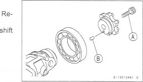
9-28
CRANKSHAFT / TRANSMISSION
Transmission
•
Remove
the holder [A] with a bearing puller [B],
Shift Drum Assembly
Be sure to install the dowel pin.
Apply a non-permanent locking agent to the threads of the shift drum cam holder bolt, and tighten it.
Torque-Shift Drum Cam Holder Bolt: 12 Nm (1.2 kgfm, 104 in-lb)
Install the holder with a steering stem bearing driver so that positioning hole [A] faces outside as shown.
Dowel Pin
57°


Shift Fork Bending
• Visually inspect the shift forks, and replace any fork that is bent. A bent fork could cause difficulty in shifting, or allow the transmission to jump out of gear when under power. 90
c [A]Shift Fork/Gear Groove Wear
Measure the thickness of the shift fork ears [A], and mea- sure the width [B] of the gear grooves.
If the thickness of a shift fork ear is less than the service limit, the shift fork must be replaced.
Shift Fork Ear Thickness
Standard: 5.9 ~ 6.0 mm (0.232 - 0.236 in.)
Service Limit: 5.8 mm (0.228 in.)
If the gear groove is worn over the service limit, the gear must be replaced.


Gear Groove Width
Standard: 6.05 - 6.15 mm (0.238 - 0.242 in.)
Service Limit: 6.25 mm (0.246 in.)
http://moto.amoti.rtt/
CRANKSHAFT
/ TRANSMISSION 9-29
Transmission
Shift
Fork Guide Pin/Drum Groove Wear
Measure
the diameter of each shift fork guide pin [A], and
measure
the width [B] of each shift drum groove.
If
the guide pin on any shift fork is less than the service
limit,
the fork must be replaced.
Shift
Fork Guide Pin Diameter
Standard: 5.9
~ 6.0 mm (0.232 - 0.236 in.)
Service
Limit: 5.8 mm (0.228 in.)
If
any shift drum groove is worn over the service limit, the
drum
must be replaced.
Shift
Drum Groove Width
Standard: 6.05
~ 6.20 mm (0.238 - 0.244 in.)
Service
Limit: 6.3 mm (0.248 in.)
Gear
Dog and Gear Dog Hole Damage
Visually
inspect the gear dogs [A] and gear dog holes [B],
Replace
any damaged gears or gears with excessively
worn
dogs or dog holes.
http://moto.amoti.rtt/

9-30
CRANKSHAFT / TRANSMISSION
Transmission
1st
Gear
2nd
Gear
3rd
Gear
4th
Gear
5th
Gear
6th
(Top) Gear
Toothed
Washer
Thrust
Washer (Thin)
Circlip
Circlip
Toothed
Washer
Thrust
Washer
Circlip
Needle
Bearing
Bearing
Outer Race
Bushing
Ball
Bearing
Oil
Seal
Steel
Ball
http://moto.amoti.ru/
WHEELS/TIRES
10-1
Wheels
/ Tires
Exploded
View
Specifications
Specia
Tools
Wheels
(Rims)
Front
Wheel Removal
Front
Wheel Installation
Rear
Wheel Removal
Rear
Wheel Installation
Wheel
Inspection
Axle
Inspection
Balance
Inspection
Balance
Adjustment
Balance
Weight Removal
Balance
Weight Installation
Tires
Air
Pressure Inspection/Adjustment...
Tire
Inspection
Tire
Removal
Tire
Installation
Tire
Repair
Hub
Bearing
Hub
Bearing Removal
Hub
Bearing Installation
Hub
Bearing Inspection
Hub
Bearing Lubrication
10-2
10-4
10-5
10-6
10-6
10-6
10-7
10-8
10-9
10-9
10-10
10-10
10-10
10-11
10-13
10-13
10-13
10-13
10-13
10-15
10-16
10-16
10-16
10-17
10-17
a
http://moto.amoti.rtt/Table of contents
10-2
WHEELS/TIRES
http://moto.amoti.rtt/
No. |
Fastener |
Torque |
Remarks |
|||
Nm |
kgf-m |
ft-lb |
||||
1 |
Front axle clamp bolts |
20 |
2.0 |
14.5 |
|
|
2 |
Front axle nut |
127 |
13.0 |
94 |
|
|
3 |
Rear axle nut |
127 |
13.0 |
94 |
|
|
G:
Apply grease.
R:
Replacement Parts
WL:
Apply soap and water solution or rubber lubricant.
http://moto.amoti.rtt/
Item |
Standard |
Service Limit |
|||
Wheels (Rims): Rim runout: Axial Radial Axle runout/100 mm Wheel balance Balance weights |
0.05 mm (0.002 in.) or less 10 g or less 10 g, 20 g, 30 g |
0.5 mm (0.02 in.) 0.8 mm (0.03 in.) 0.2 mm (0.01 in.) |
|||
Tires: Tread depth: Front Rear |
BRIDGESTONE: 3.8 mm (0.15 in.) MICHELIN: 3.8 mm (0.15 in.) |
1 mm (0.04 in.) (DE, AT, CH) 1.6 mm (0.06 in.) |
|||
BRIDGESTONE: 5.8 mm (0.23 in.) MICHELIN: 5.6 mm (0.22 in.) |
Up to 130 km/h (80 mph): 2 mm (0.08 in.) Over 130 km/h (80 mph): 3 mm (0.12 in.) |
||||
Standard tires: |
|
Make, Type |
Size |
||
Front |
BRIDGESTONE, BATTLAX BT019F RADIAL MICHELIN Pilot Sport M |
120/65 ZR17 M/C (56 W) |
|||
|
Rear |
BRIDGESTONE, BATTLAX BT012R RADIAL G MICHELIN Pilot Sport M |
180/55 ZR17 M/C (73 W) |
||
DE:
Germany AT: Austria CH:Switzerland
llstu
AriifcS
Use
the same manufacturer’s tires on both front and rear wheels.
http://mofo.amofi.rtt/
WHEELS/TIRES
10-5
57001-1129
57001-1238
Bearing
Remover Head, 4)25 x <{>28 : 57001-1346
Bearing
Remover Shaft, <{>13 : 57001-1377
http://moto.amoti.ru/A warning
Specia Tools
Inside Circlip Pliers : 57001-143


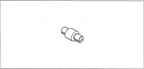

10-6
WHEELS / TIRES
Wheels
(Rims)
Front
Wheel Removal •
Remove:
Lower
Fairing (see Frame chapter) Front Fender (see Frame chapter) Brake
Caliper Mounting Bolts [A]
•
Loosen:
Riqht Side Axle Clamp Bolts [A] Axle [B]

Raise the front wheel off the ground.
Special Tool - Jack: 57001-1238
Pull out the axle to the right and drop the front wheel out of the forks.
CAUTION ~
Do not lay the wheel down on one of the discs. This can damage or warp the disc. Place blocks under the wheel so that the disc does not touch the ground.
Front Wheel Installation
NOTE
O The direction of the wheel rotation [A] is shown by an arrow [B] on the wheel spoke.
• Check the wheel rotation mark on the front wheel and install it.

http://moto.amoti.rtt/
Wheels
(Rims)
WHEELS
/ TIRES 10-7
Fit
the collars [A] on the both sides of the hub.
Tighten
the axle nut [B],
Torque
- Front Axle Nut: 127 Nm (13.0 kgf-m, 94 ft-lb)
Before
tightening the clamp bolts on the right front fork leg, pump the
front fork up and down 4 or 5 times to all on the right front fork
leg to seat on the front axle.
NOTE
O
Put
a block in front of the front wheel to stop moving.
Tighten
the axle clamp bolts [C] on the right fork leg first.
Torque
- Front Axle Clamp Bolts : 20 N m (2.0 kgf-m, 14.5 ft-lb)
Install
the front brake calipers (see Brakes chapter).
Check
the front brake effectiveness (see Brakes chapter).
Do
not attempt to drive the motorcycle until a full brake lever is
obtained by pumping the brake lever until the pads are against the
disc. The brake will not function on the first application of the
lever if this is not done. *
•
Rear
Wheel Removal
Remove
the lower fairings and side stand (see Frame chapter).
Using
the jack [A], raise the rear wheel off the ground.
O
Adjust the length of the jack legs [B], and situate the motorcycle
so that it is perpendicular to the ground.
Special
Tool - Jack: 57001-1238
•
Remove:
Cotter Pin [A] Axle Nut [B] Axle [C]

A warning

http://moto.amoti.ru/
10-8
WHEELS/TIRES
Wheels
(Rims)
Remove
the rear caliper mounting bolts and rear caliper.
Remove
the inner fender and chain cover.
Remove
the drive chain [A] from the rear sprocket toward the left.
Move
the rear wheel back and remove it.
CAUTION ~
Do
not lay the wheel on the ground with the disc facing down. This can
damage or warp the disc. Place blocks under the wheel so that the
disc does not touch the ground.
Rear
Wheel Installation
Engage
the drive chain with the rear sprocket.
Install
the caliper bracket [A] onto the swingarm stop [B], O Insert the
axle from the right side of the wheel, and tighten
the
axle nut.
O
Insert a new cotter pin into the axle, and bend its end securely to
protect the nut falling off.
Torque
- Rear Axle Nut: 127 N m (13.0 kgf-m, 94 ft-lb)
Adjust
the drive chain slack after installation (see Final Drive in the
Periodic Maintenance chapter).
Install
the rear caliper, chain cover and inner fender.
Check
the rear brake effectiveness.
Do
not attempt to drive the motorcycle until a full brake pedal is
obtained by pumping the brake pedal until the pads are against the
disc. The brake will not function on the first application of the
pedal if this is not done.
http://moto.amoti.ru/


Wheels
(Rims)
WHEELS/TIRES
10-9
Wheel
Inspection
Raise
the front/rear wheel off the ground.
Special
Tool - Jack: 57001-1238
Spin
the wheel lightly, and check for roughness or binding.
If
roughness or binding is found, replace the hub bearings.
Inspect
the wheel for small cracks, dents, bending, or warp.
If
there is any damage to the wheel, replace the wheel.
Remove
the wheel, and support it without the tire by the axle.
Measure
the rim runout, radial [A] and axial [B], with a dial gauge.
If
rim runout exceeds the service limit, check the hub bearings.
If
the problem is not due to the bearings, replace the wheel.
Rim
Runout
Service
Limit: Axial 0.5 mm (0.02 in.)
Radial 0.8
mm (0.03 in.)
Never
attempt to repair a damaged wheel. If there is any damage besides
wheel bearings, the wheel must be replaced to insure safe
operational condi; tion. *
•
Axle
Inspection
Remove
the front and rear axles.
Visually
inspect the front and rear axle for damages.
If
the axle is damaged or bent, replace it.
Place
the axle in V blocks that are 100 mm (3.94 in.) [A] apart, and set
a dial gauge [B] on the axle at a point halfway between the blocks.
Turn [C] the axle to measure the runout. The difference
between the highest and lowest dial readings is the amount of
runout.
• If
axle runout exceeds the service limit, replace the axle.

![]()

Axle Runout/100 mm (3.94 in.)
Standard: 0.05 mm (0.002 in.) or less
Service Limit: 0.2 mm (0.01 in.)
http://moto.amoti.rtt/
10-10
WHEELS / TIRES
Wheels
(Rims)
Balance
Inspection
Remove
the wheel.
Support
the wheel so that it can be spun freely.
Spin
the wheel lightly, and mark [A] the wheel at the top when the wheel
stops.
O
Repeat this procedure several times. If the wheel stops of its own
accord in various positions, it is well balanced.
If
the wheel always stops in one position, adjust the wheel balance.
Balance
Adjustment
If
the wheel always stops in one position, provisionally attach a
balance weight [A] on the rim at the marking using adhesive tape.
Rotate
the wheel 1/4 turn [B], and see whether or not the wheel stops in
this position. If it does, the correct balance weight is being
used.
If
the wheel rotates and the weight goes up, replace the weight with
the next heavier size. If the wheel rotates and the weight goes
down, replace the weight with the next lighter size. Repeat these
steps until the wheel remains at rest after being rotated 1/4 turn.
Rotate
the wheel another 1/4 turn and then another 1/4 turn to see if the
wheel is correctly balanced.
Repeat
the entire procedure as many times as necessary to achieve correct
wheel balance.
Permanently
install the balance weight.
Balance
Weight Removal When
the tire is not on the rim.
Push
[A] the blade portion toward the outside with a regular tip
screw driver, and slip the weight off the rim flange.
Discard
the used balance weight.
When
the tire is on the rim.
Pry
[A] the balance weight off the rim flange using a regular tip
screw driver as shown in the figure.
O
Insert a tip of the screw driver between the tire bead [B] and
weight blade [C] until the end of the tip reaches the end of the
weight blade.
O
Push the driver grip toward the tire so that the balance weight
slips off the rim flange.
Discard
the used balance weight.
http://moto.amoti.rtt/

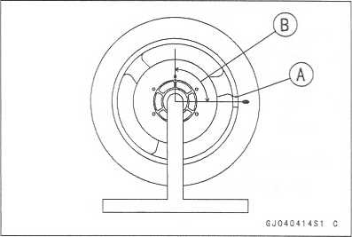

Required Total Weight |
Weight Selection |
|
One Side [A] |
Other Side [B] |
|
20g (0.71 oz) |
10g (0.35 oz) |
10g (0.35 oz) |
30g (1.06 oz) |
20g (0.71 oz) |
10g (0.35 oz) |
40g (1.41 oz) |
20g (0.71 oz) |
20g (0.71 oz) |
50g (1.76 oz) |
30g (1.06 oz) |
20g (0.71 oz) |
60g (2.12 oz) |
30g (1.06 oz) |
30g (1.06 oz) |
70g (2.47 oz) |
20g + 20g (0.71 oz + 0.71 oz) |
30g (1.06 oz) |
80g (2.82 oz) |
20g + 20g (0.71oz + 0.71 oz) |
20g + 20g (0.71oz + 0.71 oz) |
90g (3.17 oz) |
20g + 30g (0.71 oz + 1.06 oz) |
20g + 20g (0.71oz + 0.71 oz) |
Balance
Weight |
Weight |
41075-1014 |
10g (0.35 oz) |
41075-1015 |
20g (0.71 oz) |
41075-1016 |
30g (1.06 oz) |
NOTE
O
Balance
weights are available from Kawasaki dealers in 10, 20, and 30 gram
(0.35 oz, 0.71 oz, and 1.06 oz) sizes. An imbalance of less than 10
grams (0.35 oz) will not usually affect running stability.
O
Do not use four or more balance weight (more than 90 gram). If the
wheel requires an excess balance weight, disassemble the wheel to
find the cause.
http://moto.amoti.rtt/
10-12
WHEELS / TIRES
Wheels
(Rims)
•
Install
the balance weight on the rim.
O Slip the weight on the rim flange by pushing or lightly hammering the weight in the direction shown in the figure. Push or hammer [A] Tire Bead [C]
Rim Flange [B] Blade [D]
O Check that the blade [A] and weight [B] seat fully on the rim flange [C], and that the clip [D] is hooked over the rim ridge [E] and reaches rim flat portion.


http://moto.amoti.rtt/
WHEELS
/ TIRES 10-13
Tires
Air
Pressure Inspection/Adjustment
O
Refer to the Wheels/Tires in the Periodic Maintenance chapter.
Tire
Inspection
O
Refer to the Wheels/Tires in the Periodic Maintenance chapter.
Tire
Removal
Remove:
Wheel
(see this chapter)
Disc(s)
To
maintain wheel balance, mark the valve stem position on the tire
with chalk so that the tire can be reinstalled in the same
position.
Chalk
Mark or Yellow Mark [A]
Air
Valve [B]
Align
[C]
Lubricate
the tire beads and rim flanges on both sides with a soap and water
solution or rubber lubricant. This helps the tire beads slip off
the rim flanges.
CAUTION
Never
lubricate with engine oil or petroleum distillates because they
will deteriorate the tire.
Remove
the tire from the rim using a suitable commercially available
tire changer.
NOTE
O
The
tires cannot be removed with hand tools because they fit the rims
too tightly.
Tire
Installation
A
WARNING
Use
the same manufacture’s on both front and rear wheels.
Clean
the sealing surfaces of the rim and tire, and smooth the sealing
surfaces of the rim with a fine emery cloth if necessary.
Remove
the air valve and discard it.
CAUTION
Replace
the air valve whenever the tire is replaced. Do not reuse the air
valve.
http://mofo.amofi.ru/
Valve Core (let out the air)

Inspect the rim and tire, and replace them if necessary.
10-14
WHEELS/TIRES
Tires
•
Install
a new valve in the rim.
O Remove the valve cap, lubricate the stem seal [A] with a soap and water solution or rubber lubricant, and pull the valve stem [B] through the rim from the inside out until it snaps into place.
CAUTION
Do not use engine oil or petroleum distillates to lubricate the stem because they will deteriorate the rubber.
OThe air valve is shown in the figure.
Valve Cap [C] Stem Seal [E] Valve Seat
Valve Core [D] Valve Stem [F] Valve Opened


Apply a soap and water solution, or rubber lubricant to the rim flange and tire beads.
Check the tire rotation mark on the front and rear tires and install them on the rim accordingly.
Tire Rotation Mark [A]
Rotating Direction [B]

Position the tire on the rim so that the valve [A] align with the tire balance mark [B] (the chalk mark made during removal, or the yellow paint mark on a new tire).
Install the tire bead over the rim flange using a suitable commercially available tire changer.
Lubricate the tire beads and rim flanges with a soap and water solution or rubber lubricant to help seat the tire beads in the sealing surfaces of the rim while inflating the tire.
Center the rim in the tire beads, and inflate the tire with compressed air until the tire beads seat in the sealing surfaces.
Be sure to install the valve core whenever inflating the tire, and do not inflate the tire to more than 400 kPa (4.0 kgf/cm2, 57 psi). Overinflation can explode the tire with possibility of injury and loss of life.

http://moto.amoti.ru/
Tires
WHEELS/TIRES
10-15
Check
to see that the rim lines [A] on both sides of the tire sidewalls
are parallel with the rim flanges.
If
the rim flanges and tire sidewall rim lines are not parallel,
remove the valve core.
Lubricate
the rim flanges and tire beads.
Install
the valve core and inflate the tire again.
After
the tire beads seat in the rim flanges, check for air leakage.
O
Inflate the tire slightly above standard inflation.
O
Use a soap and water solution or submerge the tire, and check for
bubbles that would indicate leakage.
Adjust
the air pressure to the specified pressure (see Tire Inspection).
Install
the air valve cap.
Install
the brake disc(s) so that the marked side faces out (see Brakes
chapter).
Adjust
the wheel balance (see Balance Adjustment).
Tire
Repair
Currently
two types of repair for tubeless tires have come into wide use. One
type is called a temporary (external) repair which can be
carried out without removing the tire from the rim, and the other
type is called permanent (internal) repair which requires tire
removal. It is generally understood that higher running
durability is obtained by permanent (internal) repairs than by
temporary (external) ones. Also, permanent (internal) repairs have
the advantage of permitting a thorough examination for secondary
damage not visible from external inspection of the tire. For these
reasons, Kawasaki does not recommend temporary (external)
repair. Only appropriate permanent (internal) repairs are
recommended. Repair methods may vary slightly from make to make.
Follow the repair methods indicated by the manufacturer of the
repair tools and materials so that safe results can be obtained.
http://moto.amoti.rtt/

10-16
WHEELS/TIRES
Hub
Bearing
Hub
Bearing Removal
•
Remove
the wheel, and take out the following. Collars
Coupling (out of rear hub)
Grease Seals
Circlips [A] (Rear Hub only)
Special Tool - Inside Circlip Pliers: 57001-143 [B]
• Use the bearing remover to remove the hub bearing [A],
CAUTIONDo not lay the wheel on the ground with the disc facing down. This can damage or warp the disc. Place blocks under the wheel so that the disc does not touch the ground.
Special Tools - Bearing Remover Shaft, <)>13: 57001-1377 [B]
Bearing Remover Head, <j>25 * <j>28: 57001-1346 [C]


Hub Bearing Installation
Before installing the wheel bearings, blow any dirt or foreign particles out of the hub with compressed air to prevent contamination of the bearings.
Replace the bearings with new ones.
NOTE
o Install the bearings so that the marked side faces out.
Install the bearings by using the bearing driver set which does not contact the bearing inner race.
Press in each right the bearing [A] until they are bottomed. Special Tool - Bearing Driver Set: 57001-1129 [B]
Replace the circlips with new ones (rear hub only). Special Tool - Inside Circlip Pliers: 57001-143
Replace the grease seals with new ones.
Press in the grease seals [A] so that the seal surface is flush [B] with the end of the hole.
O Apply high temperature grease to the grease seal lips. Special Tool - Bearing Driver Set: 57001-1129 [C]


http://moto.amoti.rtt/
WHEELS/TIRES
10-17
Hub
Bearing
Hub
Bearing Inspection
Since
the hub bearings are made to extremely close tolerances, the
clearance can not normally be measured.
NOTE
O
Do not
remove any bearings for inspection. If any bearings are
removed, they will need to be replaced with new ones.
Turn
each bearing in the hub back and forth [A] while checking for
plays, roughness, or binding.
If
bearing play, roughness, or binding is found, replace the bearing.
Examine
the bearing seal [B] for tears or leakage.
If
the seal is torn or is leaking, replace the bearing.
Hub
Bearing Lubrication
NOTE
O
Since
the hub bearings are packed with grease and sealed, lubrication is
not required.
http://moto.amoti.rtt/

FINAL
DRIVE 11-1
Exploded
View 11-2
Specifications
11-4
Special
Tools 11-5
Drive
Chain 11-6
Drive
Chain Slack Inspection 11-6
Drive
Chain Slack Adjustment 11-6
Wheel
Alignment Inspection/Adjustment 11-6
Drive
Chain Wear Inspection 11-6
Drive
Chain Lubrication 11-6
Drive
Chain Removal 11-6
Drive
Chain Installation 11-6
Sprocket,
Coupling 11-7
Engine
Sprocket Removal 11-7
Engine
Sprocket Installation 11
-8
Rear
Sprocket Removal 11
-8
Rear
Sprocket Installation 11
-8
Coupling
Installation 11-9
Coupling
Bearing Removal 11-9
Coupling
Bearing Installation 11-9
Coupling
Bearing Inspection 11-10
Coupling
Bearing Lubrication 11-10
Coupling
Damper Inspection 11-10
Sprocket
Wear Inspection 11-10
Rear
Sprocket Warp Inspection 11-11
http://moto.amoti.rtt/Final Drive table of contents
11-2
FINAL DRIVE
Exploded
View

No. |
Fastener |
Torque |
Remarks |
||||
Nm |
kgf-m |
ft-lb |
|||||
1 |
Speed sensor bolt |
3.9 |
0.40 |
35 in-lb |
L |
||
2 |
Engine sprocket cover bolts |
6.9 |
0.70 |
61 in-lb |
|
||
3 |
Engine sprocket nut |
125 |
13.0 |
92 |
MO |
||
4 |
Rear axle nut |
127 |
13.0 |
94 |
|
||
5 |
Rear sprocket nuts |
59 |
6.0 |
43 |
|
||
L:
Apply a non-permanent locking agent. MO: Apply molybdenum disulfide
oil solution. R: Replacement parts.
http://moto.amoti.rtt/G: Apply grease. Ho: Apply heavy oil.
Item |
Standard |
Service Limit |
Drive Chain: Standard chain Make |
ENUMA |
|
Type |
EK520MVXL, Endless |
— — — |
Link |
108 links |
— |
Sprockets: Rear sprocket warp |
0.4 mm (0.016 in.) or less |
0.5 mm (0.02 in.) |
http://mofo.amofi.rtt/
FINAL
DRIVE 11-5
57001-143 57001-1238
57001-1129
http://moto.amoti.rtt/Special Tools
Inside Circlip Pliers : Jack :


11-6
FINAL DRIVE
Drive
Chain
Drive
Chain Slack Inspection
o
Refer to the Final Drive in the Periodic Maintenance chapter.
Drive
Chain Slack Adjustment
O
Refer to the Final Drive in the Periodic Maintenance chapter.
Wheel
Alignment Inspection/Adjustment O
Refer to the Final Drive in the Periodic Maintenance chapter.
Drive
Chain Wear Inspection
O
Refer to the Final Drive in the Periodic Maintenance chapter.
Drive
Chain Lubrication
O
Refer to the Final Drive in the Periodic Maintenance chapter.
Drive
Chain Removal •
Remove:
Chain
Cover/lnner Fender Screws [A]
Inner
Fender (see Frame chapter) [B]
Chain
Cover [C]
Rear
Wheel (see Wheels/Tires chapter)
Swingarm
(see Suspension chapter)
Engine
Sprocket Cover (see Engine Sprocket Removal)
•
Disengage
the drive chain [A] from the engine sprocket [B], and take it off
the chassis.
Drive Chain Installation
Engage the drive chain to the engine sprocket.
Install:
Swingarm (see Suspension chapter)
Rear Wheel (see Wheels/Tires chapter)
Engine Sprocket Cover (see Engine Sprocket Installation)
Chain Cover Inner Fender
O Fit the flap [A] of the chain cover into the slot [B] in the swingarm.
Adjust the drive chain slack after installing the chain (see Final Drive in the Periodic Maintenance chapter).

http://moto.amoti.rtt/
Sprocket,
Coupling
FINAL
DRIVE 11-7
Engine
Sprocket Removal •
Remove:
Speed
Sensor Bolt [A]
Speed
Sensor [B]
Engine
Sprocket Cover Bolts [C] Engine Sprocket Cover [D]
Flatten
out the bended washer [A],
Remove
the engine sprocket nut [B] and washer.
NOTE
O
When
loosening the engine sprocket nut, hold the rear brake on.
Using
the jack, raise the rear wheel off the ground. Special
Tool - Jack : 57001-1238
Remove
the axle cotter pin, and loosen the rear axle nut.
Loosen
the both chain adjuster locknut to loosen the drive chain.
Remove
the drive chain from the rear sprocket toward the right.
Disengage
the drive chain [A] from the engine sprocket [B]-
Pull
the engine sprocket off the output shaft [C],
http://moto.amoti.ru/

Rear Sprocket Removal • Remove the rear wheel (see Wheels/Tires chapter). |
|
|
CAUTION |
|
|
Do not lay the wheel on the ground with the disc |
|
|
facing down. This can damage or warp the disc. |
|
|
Place blocks under the wheel so that the disc does |
|
c—:^==^0/ |
not touch the ground. |
|
|
• Remove the rear sprocket nuts [A], |
GK050'09S1 C |
|
•
Remove
the rear sprocket [B],
Rear Sprocket Installation
Install the sprocket facing the tooth number marking [A] outward.
Tighten the rear sprocket nuts.
Torque - Rear Sprocket Nut : 59 N-m (6.0 kgf-m, 43 ft-lb)
Install the rear wheel (see Wheels/Tires chapter).

http://moto.amoti.rtt/
FINAL DRIVE 11-9
Sprocket, Coupling
Coupling Installation
• Grease the following and install the coupling. Coupling Grease Seal [A]
Coupling Internal Surface [B]
Ball Bearing [C]
Coupling Bearing Removal
• Remove:
Coupling Grease Seal Circlip [A]
Special Tool * Inside Circlip Pliers: 57001-143 [b]
• Remove the bearing [A] by tapping from the wheel side. Special Tool - Bearing Driver Set: 57001-1129 [B]
Coupling Bearing Installation
Replace the bearing with a new one.
Press in the bearing [A] until it is bottomed. Special Tool - Bearing Driver Set: 57001-1129 [B]
Pack the bearing with high temperature grease.
Replace the circlip with a new one.
Special Tool - Inside Circlip Pliers: 57001-143


6J09006BS1 C
• Replace the grease seal with a new one.
Press in the grease seal so that the seal surface is flush with the end of the hole.
O Apply high temperature grease to the grease seal lips. Special Tool - Bearing Driver Set: 57001-1129
http://moto.amoti.ru/
11-10
FINAL DRIVE
Sprocket,
Coupling
Coupling
Bearing Inspection Since
the coupling bearing is made to extremely close tolerances, the
clearance can not normally be measured.
NOTE
O
It
is not necessary to remove the coupling bearing for inspection. If
the bearing is removed, it will need to be replaced with a new one.
Turn
the bearing in the coupling back and forth [A] while checking for
plays, roughness, or binding.
If
bearing play, roughness, or binding is found, replace the bearing.
Examine
the bearing seal [B] for tears or leakage.
If
the seal is torn or is leaking, replace the bearing.
Coupling
Bearing Lubrication
•
Pack
the bearing with good quality bearing grease. Turn the bearing
around by hand a few times to make sure the grease is distributed
uniformly inside the bearing.

Coupling Damper Inspection
Remove the rear wheel coupling, and inspect the rubber dampers [A],
Replace the damper if it appears damaged or deteriorated.
Sprocket Wear Inspection
Visually inspect the engine and rear sprocket teeth for wear and damage.
If the teeth are worn as illustrated, replace the sprocket, and inspect the drive chain wear (see Final Drive in the Periodic Maintenance chapter).
Worn Tooth (Engine Sprocket)
Worn Tooth (Rear Sprocket)
Direction of Rotation
NOTE
o If a sprocket requires replacement, the chain is probably worn also.
When replacing a sprocket, inspect the chain.

http://moto.amoti.rtt/
Sprocket,
Coupling
FINAL
DRIVE 11-11
Rear
Sprocket Warp Inspection
Raise
the rear wheel off the ground (see Wheels/Tires chapter) so that it
will turn freely.
Set
a dial gauge [A] against the rear sprocket [B] near the teeth as
shown, and rotate [C] the rear wheel to measure the sprocket runout
(warp). The difference between the highest and lowest dial gauge
readings is the amount of runout (warp).
Rear
Sprocket Warp
Standard: 0.4
mm (0.016 in.) or less
Service
Limit: 0.5 mm (0.02 in.)
http://moto.amoti.rtt/
If the runout exceeds the service limit, replace the rear sprocket.

BRAKES
12-1
Exploded
View 12-2
Specifications
12-6
Special
Tools 12-7
Brake
Pedal 12-8
Brake
Lever Position Adjustment 12-8
Brake
Pedal Position Inspection 12-8
Brake
Pedal Position Adjustment.... 12-8
Calipers
12-9
Front
Caliper Removal 12-9
Rear
Caliper Removal 12-9
Caliper
Installation 12-10
Front
Caliper Disassembly 12-10
Front
Caliper Assembly 12-11
Rear
Caliper Disassembly 12-12
Rear
Caliper Assembly 12-12
Caliper
Fluid Seal Damage 12-13
Caliper
Dust Seal/Friction Boot
Damage
12-13
Caliper
Piston and Cylinder
Damage
12-14
Caliper
Holder Shaft Wear 12-14
Brake
Pads 12-15
Front
Brake Pad Removal 12-15
Front
Brake Pad Installation 12-15
Rear
Brake Pad Removal 12-15
Rear
Brake Pad Installation 12-16
Brake
Pad Wear Inspection 12-16
Master
Cylinder 12-17
Front
Master Cylinder Removal 12-17
Front
Master Cylinder Installation .... 12-17
Rear
Master Cylinder Removal 12-18
Rear
Master Cylinder Installation 12-18
Front
Master Cylinder Disassembly. 12-18 Rear Master Cylinder
Disassembly.. 12-19
Master
Cylinder Assembly 12-19
Master
Cylinder Inspection (Visual
Inspection)
12-19
Brake
Disc 12-20
Brake
Disc Removal 12-20
Brake
Disc Installation 12-20
Brake
Disc Wear 12-20
Brake
Disc Warp 12-20
Brake
Fluid 12-21
Level
Inspection 12-21
Brake
Fluid Change 12-21
Bleeding
the Brake Line 12-21
Brake
Hose 12-22
Brake
Hose Removal/lnstallation 12-22
Brake
Hose Inspection 12-22
http://moto.amoti.rtt/Brakes table of contents
12-2
BRAKES
Exploded
View
http://moto.amoti.rtt/
No. |
Fastener |
Torque |
Remarks |
||
N-m |
kgf-m |
ft-lb |
|||
1 |
Brake lever pivot bolt |
1.0 |
0.10 |
89 in-lb |
Si |
2 |
Front master cylinder clamp bolts |
8.8 |
0.90 |
78 in-lb |
S |
3 |
Front brake light switch screw |
1.2 |
0.12 |
10 in-lb |
|
4 |
Front brake reservoir cap stopper screw |
1.2 |
0.12 |
10 in-lb |
|
5 |
Brake lever pivot bolt locknut |
6.0 |
0.61 |
53 in-lb |
|
6 |
Brake hose banjo bolts |
25 |
2.5 |
18 |
|
7 |
Front caliper mounting bolts |
34 |
3.5 |
25 |
|
8 |
Front caliper assembly bolts |
22 |
2.2 |
16 |
|
9 |
Front brake pad pins |
15 |
1.5 |
11 |
|
10 |
Front brake disc mounting bolts |
27 |
2.8 |
20 |
L |
11 |
Bleed valves |
7.8 |
0.80 |
69 in-lb |
|
B:
Apply brake fluid.
R:
Replacement Parts S: Follow the specific tightening sequence. Si:
Apply silicone grease (ex. PBC grease). L: Apply a non-permanent
locking agent.
http://mofo.amofi.ru/
12-4
BRAKES
Exploded
View
http://moto.amoti.rtt/
No. |
Fastener |
Torque |
Remarks |
||
Nm |
kgf-m |
ft-lb |
|||
1 |
Brake hose banjo bolts |
25 |
2.5 |
18 |
|
2 |
Rear master cylinder mounting bolts |
25 |
2.5 |
18 |
|
3 |
Rear master cylinder push rod locknut |
18 |
1.8 |
13 |
|
4 |
Bleed valve |
7.8 |
0.80 |
69 in-lb |
|
5 |
Rear brake disc mounting bolts |
27 |
2.8 |
20 |
L |
6 |
Rear caliper mounting bolts |
25 |
2.5 |
18 |
|
B:
Apply brake fluid.
G:
Apply grease.
R:
Replacement Parts Si: Apply silicone grease (ex. PBC grease). L:
Apply a non-permanent locking agent.
http://moto.amoti.rtt/
Item |
Standard |
Service Limit |
Brake Lever, Brake Pedal: |
|
|
Brake lever position |
5-way adjustable (to suit rider) |
— |
Brake lever free play |
Non-adjustable |
, . . |
Pedal free play |
Non-adjustable |
— |
Pedal position |
About 45 mm (1.8 in.) below footpeg top |
- - - |
Brake Discs: |
|
|
Thickness |
|
|
Front |
5.8 - 6.2 mm (0.23 ~ 0.24 in.) |
5.5 mm (0.22 in.) |
Rear |
4.8 ~ 5.1 mm (0.19 ~ 0.20 in.) |
4.5 mm (0.18 in.) |
Runout |
0.15 mm (0.006 in.) or less |
0.3 mm (0.01 in.) |
http://mofo.amofi.rtt/
BRAKES
12-7
Jack
:
http://moto.amoti.rtt/Special Tools
Inside Circlip Pliers : 57001-143


12-8
BRAKES
Brake
Pedal
Brake
Lever Position Adjustment The
brake lever adjuster has 5 positions so that the brake lever
position can be adjusted to suit the operator’s hand.
•
Push
the lever forward and turn the adjuster [A] to align the number with
the arrow mark [B] on the lever holder.
O The distance from the grip to the lever is minimum at number 5 and maximum at number 1.
Brake Pedal Position Inspection
Check that the brake pedal [A] is in the correct position.
[B] Footpeg
Pedal Position
Standard: About 45 mm (1.8 in.) [C] below top of
footpeg
If it is incorrect, adjust the brake pedal position.

Brake Pedal Position Adjustment
NOTE
o Usually it is not necessary to adjust the pedal position, but always adjust it when push rod locknut has been loosened.
• Remove the rear master cylinder cover [B], and then tighten the master cylinder bolts [A] only.
•• Loosen the locknut [A] and turn the push rod with the hex head [B] to achieve the correct pedal position.
If the length [C] shown is 67 ± 1 mm (2.6 ± 0.04 in.), the pedal position will be within the standard range.
Tighten:
Torque - Rear Master Cylinder Push Rod Locknut: 18 N m (1.8 kgfrn, 13 ft-lb)
Check the brake light switch operation (see Brakes in the Periodic Maintenance chapter).

http://moto.amoti.ru/
Calipers
BRAKES
12-9
Front
Caliper Removal
Loosen
the banjo bolt [A] at the brake hose lower end, and tighten it
loosely.
Unscrew
the caliper mounting bolts [B], and detach the caliper [C] from the
disc.
Do
not loosen the caliper assembly bolts [D], Take out only the caliper
mounting bolts for caliper removal. Loosening the caliper
assembly bolts will cause brake fluid leakage.
Unscrew
the banjo bolt and remove the brake hose [E] from the caliper (see
Brake Hose Removal/lnstallation).
o
If
the caliper is to be disassembled after removal and if compressed
air is not available, disassemble the caliper before the brake hose
is removed (see Front Caliper Disassembly).

Caution
Caution
Immediately wash away any brake fluid that spills. Note

Loosen the banjo bolt [A] at the brake hose lower end, and tighten it loosely.
Unscrew the caliper mounting bolts [B], and detach the caliper [C] from the disc.
Unscrew the banjo bolt and remove the brake hose [D] from the caliper (see Brake Hose Removal/lnstallation).
Caution
Immediately wash away any brake fluid that spills.
NOTE
O
If
the caliper is to be disassembled after removal and if compressed
air is not available, disassemble the caliper before the brake hose
is removed (see Rear Caliper Disassembly).
http://moto.amoti.ru/
12-10
BRAKES
Calipers
Caliper
Installation
Install
the caliper and brake hose lower end.
O
Replace the washers on each side of hose fitting with new ones.
Tighten:
Torque
- Caliper Mounting Bolts (Front): 34 N-m (3.5 kgf-m, 25 ft lb)
Caliper
Mounting Bolts (Rear): 25 N m (2.5 kgf-m, 18 ft-lb)
Brake
Hose Banjo Bolt: 25 N m (2.5 kgf-m, 18 ft-lb)
Check
the fluid level in the brake reservoirs.
Bleed
the brake line (see Brakes in the Periodic Maintenance
chapter).
Check
the brake for good braking power, no brake drag, and no fluid
leakage.
Do
not attempt to drive the motorcycle until a full brake lever or
pedal is obtained by pumping the brake lever or pedal until the pads
are against the disc. The brakes will not function on the first
application of the lever or pedal if this is not done. *
•
Front
Caliper Disassembly
Loosen
the front caliper assembly bolt [A] and banjo bolt [B], and tighten
them loosely.
Remove:
Front
Caliper [C] (see Front Caliper Removal)
Brake
Pads (see Front Brake Pad Removal)
Front
Caliper Assembly Bolts O-rings
•
Using
compressed air, remove the pistons. One way to remove the pistons is
as follows.
A warning
O Install a rubber gasket [A] and a wooden board [B] more than 10 mm (0.4 in.) thick on the caliper half, and fasten them together with a suitable bolt and nut as shown. Leave one of the oil passages [C] open.
O Lightly apply compressed air [D] to the oil passage until the pistons hit the rubber gasket. Block the hose joint opening [E] during this operation if the caliper half has the opening.
Bolt and Nut [F]
Oil Passage sealed by Rubber Gasket. [G]
Push down. [H]

GL050488S1 C

http://moto.amoti.rtt/
Calipers
BRAKES
12-11
To
avoid serious injury, never place your fingers or palm in front of
the piston. If you apply compressed air into the caliper, the piston
may crush your hand or fingers.
OPull
out the pistons by hand.
Remove
the dust seals [A] and fluid seals [B],
Remove
the bleed valve [C] and rubber cap [D],
Repeat
the previous step to remove the pistons from the other side of the
caliper body.
NOTE
O
If
compressed air is not available,
do
as follows for both calipers coincidentally, with the brake hose
connected to the caliper.
O
Prepare
a container for brake fluid, and perform the work above it.
O
Remove
the spring and pads (see Front Brake Pad Removal).
O
Pump
the brake lever until the pistons come out of the cylinders, and
then disassemble the caliper.
Front
Caliper
Assembly
Clean
the caliper parts except for the pads.
CAUTION '
•
For
cleaning of the parts, use only disc brake fluid, isopropyl alcohol,
or ethyl alcohol.
Install
the bleed valve and rubber cap.
Torque
- Bleed Valve: 7.8 Nm (0.80 kgf-m, 69 in-lb)
Replace
the fluid seals [A] with new ones.
O
Apply brake fluid to the fluid seals, and install them into the
cylinders by hand.
• Replace
the dust seals [B] with new ones if they are damaged.A warning

O Apply brake fluid to the dust seals, and install them into the cylinders by hand.

http://moto.amoti.ru/
12-12
BRAKES
Calipers
Replace
the O-rings [A] if they are damaged.
Apply
brake fluid to the outside of the pistons, and push them into each
cylinder by hand.
Be
sure to install the O-rings.
Tighten
the caliper assembly bolts.
Torque
- Front Caliper Assembly Bolts: 22 N-m (2.2 kgf-m, 16 ft-lb)
Install
the pads (see Front Brake Pad Installation).
Wipe
up any spilled brake fluid on the caliper with wet cloth.
Rear
Caliper Disassembly
Remove
the rear caliper.
Remove
the pads and anti-rattle spring (see Rear Brake Pad Removal).
Using
compressed air, remove the piston.
o
Cover the caliper opening with a clean, heavy cloth [A],
O
Remove the piston by lightly applying compressed air [B] to where
the brake line fits into the caliper.
To
avoid serious injury, never place your fingers or palm inside the
caliper opening. If you apply compressed air into the caliper,
the piston may crush your hand or fingers.
Remove
the dust seal and fluid seal.
Remove
the bleed valve and rubber cap.
NOTE
O
If
compressed air is not available, do as follows with the brake hose
connected to the caliper.
o
Prepare
a container for brake fluid, and perform the work above it.
O
Remove
the pads and spring (see Rear Brake Pad Removal).
O
Pump
the brake pedal to remove the caliper piston.
Rear
Caliper Assembly
Clean
the caliper parts except for the pads.
CAUTION ~
•
For
cleaning of the parts, use only disc brake fluid,
• Install
the bleed valve and rubber cap.

A warning
Isopropyl alcohol, or ethyl alcohol.
Torque - Bleed Valve: 7.8 N-m (0.80 kgf-m, 69 in-lb)
http://moto.amoti.ru/
Calipers
BRAKES
12-13
Replace
the fluid seal [A] with a new one.
O
Apply brake fluid to the fluid seal, and install it into the
cylinder by hand.
Replace
the dust seal [B] with a new one if it is damaged. O Apply brake
fluid to the dust seal, and install it into the
cylinder
by hand.
Apply
brake fluid to the outside of the piston, and push it into the
cylinder by hand.
Replace
the shaft rubber friction boot [A] and dust boot [B] if they are
damaged.
Apply
a thin coat of PBC (Poly Butyl Cuprysil) grease to the caliper
holder shafts [C] and holder holes [D] (PBC is a special high
temperature, water-resistance grease).
6L050402S1
C
Install
the anti-rattle spring [A] in the caliper as shown.
Install
the pads (see Rear Brake Pad Installation).
Wipe
up any spilled brake fluid on the caliper with wet cloth.
GL056064
P
Caliper
Fluid Seal Damage
o
Refer to the Brakes in the Periodic Maintenance chapter.
Caliper
Dust Seal/Friction Boot Damage o
Refer to the Brakes in the Periodic Maintenance chapter.
http://moto.amoti.rtt/


© |
|
(d) |
© |
< |
|
|
|
QLOSOS28S1 C |
http://moto.amoti.rtt/
Brake
Pads
BRAKES
12-15
Front
Brake Pad Removal
•
Remove:
Pad Spring Bolts [A]
Pad Spring [B]
• Remove:
Brake Pads [A]

Front Brake Pad Installation
Push the caliper pistons in by hand as far as they will go.
Install the brake pads.
Install the pad pin and clip. The clip must be "outside" of the pads.
Install the pad spring and tighten the pad spring bolts.
Torque - Front Brake Pad Spring Bolts: 2.9 N m (0.30 kgf-m, 26 in-lb)
A warning
Do not attempt to drive the motorcycle until a full brake lever is obtained by pumping the brake lever and the pads are against the disc. The brake will not function on the first application of the lever if this is not done. * •
Rear Brake Pad Removal
Remove the caliper with the hose installed.
• Remove:
Clip [A]
Pad Pin [B] Brake Pads [C]

http://moto.amoti.ru/
12-16
BRAKES
Brake
Pads
Rear
Brake Pad Installation
Push
the caliper piston in by hand as far as it will go.
Install
the anti-rattle spring in place.
Install
the brake pads.
Install
the pad pin and clip. The clip must be "outside" of the
pads.
Install
the caliper (see Caliper Installation).
Do
not attempt to drive the motorcycle until a full brake pedal is
obtained by pumping the brake pedal until the pads are against the
disc. The brake will not function on the first application of the
pedal if this is not done.
Brake
Pad Wear Inspection
O
Refer to the Brakes in the Periodic Maintenance chapter.
http://moto.amoti.ru/
A warning
BRAKES
12-17
Master
Cylinder
Front
Master Cylinder Removal •
Loosen the reservoir bracket bolts [A],
Disconnect
the front brake light switch connectors.
Remove
the banjo bolt [A] to disconnect the brake hose from the master
cylinder (see Brake Hose Removal/ln- stallation).
Unscrew
the clamp bolts [B], and take off the master cylinder [C] as
an assembly with the reservoir, brake lever, and brake switch
installed.
CAUTION
Front
Master Cylinder Installation
Set
the front master cylinder to match its mating surface [A] to the
punch mark [B] of the handlebar.
The
master cylinder clamp must be installed with the arrow mark
[C] upward.
Tighten
the upper clamp bolt first, and then the lower clamp bolt. There
will be a gap at the lower part of the clamp after tightening.
Torque
- Front Master Cylinder Clamp Bolts: 8.8 N-m (0.90 kgf-m, 78 in-lb)
Replace
the washers that are on each side of the hose fitting with new
ones.
• Tighten:
Immediately wash away any brake fluid that spills. * •
Torque - Brake Hose Banjo Bolt: 25 N-m (2.5 kgf-m, 18 ft-lb)
Bleed the brake line (see Brakes in the Periodic Maintenance chapter).
Check the brake for good braking power, no brake drag, and no fluid leakage.


http://moto.amoti.rtt/
Rear
Master Cylinder Removal
Unscrew
the brake hose banjo bolt [A] on the master cylinder (see
Brake Hose Removal/lnstallation).
Pull
off the reservoir hose lower end [B], and drain the brake fluid
into a container.
Remove
the cotter pin [C] and join pin [D],
NOTE
O
Pull
off the joint pin while pressing down the brake pedal.
Unscrew
the master cylinder mounting bolts [E], and take off the master
cylinder [F] and master cylinder cover [Gj.
Rear
Master Cylinder Installation
Replace
the cotter pin with a new one.
Replace
the washers that are on each side of hose fitting with new ones.
Tighten:
Torque
- Rear Master Cylinder Mounting Bolts: 25 Nm (2.5 kgf-m, 18 ft-lb)
Brake
Hose Banjo Bolt: 25 N m (2.5 kgf-m, 18 ft-lb)
Bleed
the brake line (see Brakes in the Periodic Maintenance
chapter).
Check
the brake for good braking power, no brake drag, and no fluid
leakage.
Front
Master Cylinder Disassembly
Remove
the front master cylinder (see Front Master Cylinder Removal).
Remove
the reservoir cap and diaphragm, and pour the brake fluid into a
container.
Unscrew
the locknut and pivot bolt, and remove the brake lever.
Pull
the dust cover out of place, and remove the circlip. Special
Tool - Inside Circlip Pliers: 57001-143
Pull
out the piston [A], secondary cup [B], primary cup [C], and return
spring [Dj.
CAUTION
Do
not remove the secondary cup from the piston since removal will
damage it.
http://moto.amoti.rtt/18 Brakes Master Cylinder


Master
Cylinder
BRAKES
12-19
Rear
Master Cylinder Disassembly
NOTE
O
Do
not remove the push rod clevis for master cylinder disassembly since
removal requires brake pedal position adjustment.
Remove
the rear master cylinder (see Rear Master Cylinder Removal).
Slide
the dust cover on the push rod out of place, and remove the
circlip.
Special
Tool - Inside Circlip Pliers: 57001-143
Pull
out the push rod with the piston stop.
Take
off the piston [A], secondary cup [B], primary cup [C], and return
spring [D],
Do
not remove the secondary cup from the piston since removal will
damage it.
Master
Cylinder Assembly
Before
assembly, clean all parts including the master cylinder with brake
fluid or alcohol.
Except
for the disc pads and disc, use only disc brake fluid, isopropyl
alcohol, or ethyl alcohol for cleaning of the brake parts. Do not
use any other fluid for cleaning of these parts, Gasoline, engine
oil, or any other petroleum distillate will cause deterioration
of the rubber parts. Oil spilled on any part will be difficult to
wash off completely, and will eventually deteriorate the rubber used
in the disc brake. *
•
Apply
brake fluid to the removed parts and to the inner wall of the
cylinder.
Take
care not to scratch the piston or the inner wall of the cylinder.
Apply
silicone grease (ex. PBC grease)
Brake
Lever Pivot Bolt Brake Lever Pivot Contact Push Rod Contact (Rear)
Dust
Covers
• Tighten:
Caution

Caution
Torque - Brake Lever Pivot Bolt: 1.0 N-m (0.10 kgf-m, 9 in-lb)
Brake Lever Pivot Bolt Locknut: 5.9 N-m (0.60 kgf-m, 52 in-lb)
Master Cylinder Inspection (Visual Inspection)
O Refer to the Brakes in the Periodic Maintenance chapter.
http://moto.amoti.ru/
12-20
BRAKES Brake Disc
Brake
Disc Removal
Remove
the wheel (see Wheels/Tires chapter).
Unscrew
the mounting bolts, and take off the disc.
Remove
the gasket (Front Brake Disc only).
Brake
Disc Installation
Replace
the gasket with a new one (Front Brake Disc only).
Install
the brake disc on the wheel so that the marked side [B] faces out.
Apply
a non-permanent locking agent to the threads of the rear brake disc
mounting bolts [A],
Tighten:
Torque
- Brake Disc Mounting Bolts: 27 N-m (2.8 kgf m, 20
ft-lb)
Brake
Disc Wear
Measure
the thickness of each disc [A] at the point where it has worn the
most.
If
the disc has worn past the service limit, replace it.
[B]
Measuring Area
Front
Brake Discs Thickness
Standard: 5.8
~ 6.2 mm (0.23 ~ 0.24 in.)
Service
Limit: 5.5 mm (0.22 in.)
Rear
Brake Discs Thickness
Standard: 4.8
~ 5.1 mm (0.19 - 0.20 in.)
Service
Limit: 4.5 mm (0.18 in.)
Brake
Disc Warp
Jack
up the motorcycle so that the wheel is off the ground (see
Wheels/Tires chapter).
Special
Tool - Jack: 57001-1238
OFor
front disc inspection, turn the handlebar fully to one side.
Set
up a dial gauge against the disc [A] as shown and measure disc
runout, while turning [B] the wheel by hand.
If
runout exceeds the service limit, replace the disc.
Disc
Runout
Standard: 0.15
mm (0.006 in.) or less
Service
Limit: 0.3 mm (0.01 in.)
http://moto.amoti.rtt/


BRAKES
12-21
Brake
Fluid
Level
Inspection
O
Refer to the Brakes in the Periodic Maintenance chapter. Brake
Fluid Change
O
Refer to the Brakes in the Periodic Maintenance chapter. Bleeding
the Brake Line
O
Refer to the Brakes in the Periodic Maintenance chapter.
http://moto.amoti.rtt/
12-22
BRAKES
Brake
Hose
Brake
Hose Removal/lnstallation
CAUTION
Brake
fluid quickly ruins painted or plastic surfaces; any spilled
fluid should be completely wiped up immediately with wet cloth. *
•
When
removing the brake hose, take care not to spill the brake fluid on
the painted or plastic parts.
When
removing the brake hose, temporarily secure the end of the brake
hose to some high place to keep fluid loss to a minimum.
There
are washers on each side of the brake hose fitting. Replace them
with new ones when installing.
When
installing the hoses, avoid sharp bending, kinking, flattening or
twisting, and route the hoses according to Cable, Wire, and Hose
Routing section in Appendix chapter.
• Tighten:
Torque - Brake Hose Banjo Bolts: 25 Nm (2.5 kgf-m, 18 ft lb)
Bleed the brake line after installing the brake hose (see Brakes in the Periodic Maintenance chapter).
Brake Hose Inspection
O Refer to the Brakes in the Periodic Maintenance chapter.
http://moto.amoti.ru/
SUSPENSION
13-1
Exploded
View 13-2
Specifications
13-6
Special
Tools 13-7
Front
Fork 13-9
Rebound
Damping Force Adjustment 13-9
Compression
Damping Force Adjustment 13-9
Spring
Preload Adjustment 13-10
Front
Fork Removal (each fork leg) 13-10
Front
Fork Installation 13-11
Front
Fork Oil Change 13-11
Front
Fork Disassembly 13-15
Front
Fork Assembly 13-16
Inner
Tube Inspection 13-17
Dust
Seal Inspection 13-17
Spring
Tension 13-17
Rear
Shock Absorber 13-18
Rebound
Damping Force Adjustment 13-18
Compression
Damping Force Adjustment 13-18
Spring
Preload Adjustment 13-18
Rear
Shock Absorber Removal 13-19
Rear
Shock Absorber Installation 13-20
Rear
Shock Absorber Inspection 13-20
Rear
Shock Absorber Scrapping 13-20
Swingarm
13-21
Swingarm
Removal 13-21
Swingarm
Installation 13-22
Swingarm
Bearing Removal 13-23
Swingarm
Bearing Installation 13-23
Swingarm
Bearing, Sleeve Inspection 13-23
Swingarm
Pivot Lubrication 13-23
Chain
Guide Inspection 13-24
Tie-Rod,
Rocker Arm 13-25
Tie-Rod
Removal 13-25
Tie-Rod
Installation 13-25
Rocker
Arm Removal 13-25
Rocker
Arm Installation 13-25
Rocker
Arm/Tie-Rod Bearing, Sleeve Inspection 13-26
Rocker
Arm/Tie-Rod Lubrication 13-26
http://moto.amoti.rtt/Suspension table of contents
13-2
SUSPENSION
Exploded
View
http://moto.amoti.rtt/
No. |
Fastener |
Torque |
Remarks |
|||
N-m |
kgf-m |
ft-lb |
||||
1 |
Front fork top plug |
23 |
2.3 |
17 |
|
|
2 |
Front fork clamp bolts (upper) |
20 |
2.0 |
14.5 |
|
|
3 |
Front fork clamp bolts (lower) |
20 |
2.0 |
14.5 |
|
|
4 |
Front fork bottom alien bolts |
40 |
4.0 |
30 |
L |
|
5 |
Front axle clamp bolts |
20 |
2.0 |
14.5 |
|
|
6 |
Piston rod nut |
15 |
1.5 |
11 |
|
|
L:
Apply a non-permanent locking agent. R: Replacement Parts
http://moto.amoti.rtt/
13-4
SUSPENSION
6M020S«a«S
c
http://moto.amoti.ru/
Exploded View

No. |
Fastener |
Torque |
Remarks |
|||
Nm |
kgf-m |
ft-lb |
||||
1 |
Rear shock absorber bracket nut |
59 |
6.0 |
43 |
|
|
2 |
Rear shock absorber Nuts (upper and lower) |
34 |
3.5 |
25 |
|
|
3 |
Tie-Rod Nuts |
59 |
6.0 |
43 |
|
|
4 |
Uni-Trak rocker arm nut |
34 |
3.5 |
25 |
|
|
5 |
Swingarm pivot shaft nut |
108 |
11 |
81 |
|
|
6 |
Swingarm pivot shaft ZX636 ZX600 |
20 |
2.0 |
14 |
|
|
25 |
2.5 |
18 |
|
|||
7 |
Swingarm pivot shaft locknut |
98 |
10 |
72 |
|
|
Specifications |
|
|
Item |
Standard
|
|
Front Fork (per one unit): Fork inner tube diameter Air Pressure Rebound damper setting Compression damper setting Fork spring preload setting Fork Oil: |
<j> 41 mm (1.6 in.) Atmospheric pressure (Non-adjustable) 8th click from the first click of the fully clockwise position (Usable Range: 0 <—» 11 clicks) 8th click from the first click of the fully clockwise position (Usable Range: 0 <—> 13 clicks) Adjuster protrusion is 14 mm (0.55 in.) (Usable Range: 4 ~ 19 mm) (0.16 ~ 0.75 in.) |
|
Viscosity Amount: |
SAE 10W |
|
When changing oil After disassembly and completely dry |
Aprox. 410 mL (13.9 US oz.) 482 ± 4 mL (16.3 ± 0.14 US oz.) |
|
Fork oil level: (fully compressed, without spring, below from the top of the inner tube) |
101 ± 2 mm (3.98 ± 0.08 in.) |
|
Fork spring free length |
248 mm (9.76 in.) (Service limit: 243 mm (9.57 in.)) |
|
Rear Shock Absorber: Rebound damper set Compression damper set Spring preload setting position |
4 1/4 turns out from the fully clockwise position (Usable Range: 0 <—> 4 1/2 turns out) 3 1/2 turns out from the fully clockwise position (Usable Range: 0 <—> 4 turns out) |
|
Standard Usable range Gas pressure |
Spring length: 180 mm (7.1 in.) Spring length: 171.5 - 191.5 mm (6.8 ~ 7.5 in.) (weaker to stronger) 980 kPa (10 kgf/cm2, 142 psi, Non-adjustable) |
|
http://moto.amoti.rtt/
SUSPENSION
13-7
57001-1058
57001-1129
57001-1238
57001-1288
Fork
Piston Rod Puller, M10 x 1.0: 57001-1298
57001-1316
57001-1522
57001-1533
57001-1537
http://moto.amoti.rtt/Special Tools
Inside Circlip Pliers : 57001-143


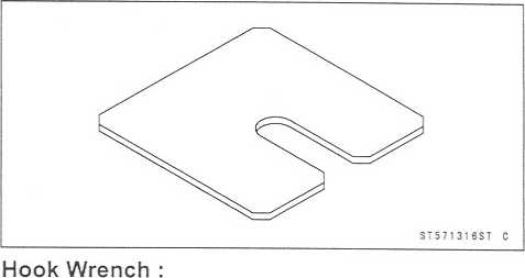


13-8
SUSPENSION
Special
Tools
Fork
Spring Compressor: 57001-1540
Swingarm
Pivot Nut Wrench : 57001-1541
http://moto.amoti.rtt/

Adjuster Position |
Damping Force |
Setting |
Load |
Road |
Speed |
11 |
Weak |
Soft |
Light |
Good |
Low |
|
f |
t |
t |
t |
|
1 |
1 |
|
|
4 |
4 |
0 |
Strong |
Hard |
Heavy |
Bad |
High |
Compression
Damping Force Adjustment •
To adjust the compression damping force, turn the compression
damping adjuster [A] until you feel a click.
OThe
standard adjuster setting for the average-build rider of 68 kg
(150 lb) with no passenger and no accessories is the 8th
click from
the 1st click of the fully clockwise position.
If
both adjusters are not adjusted equally, handling may be
impaired and a hazardous condition may result.
O
The damping force can be left soft for average riding. But it
should be adjusted harder for high speed riding or riding with a
passenger. If the damping feels too soft or too stiff, adjust it
in accordance with the following table.
Compression
Damping Force Adjustment Position |
Damping Force |
Setting |
Load |
Road |
Speed |
13 |
Weak |
Soft |
Light |
Good |
Low |
|
T |
I |
t |
T |
T |
4 |
4 |
'i' |
4 |
4' |
4 |
0 |
Strong |
Hard |
Heavy |
Bad |
High |
(Counterclockwise) (Clockwise)
Softer
►Harder
STD
i
131211109
8 7 6 5 4 3 2 1
H-W
I I I I I I II i I H
, ,
i
Seated
pos i t i on,
adjuster
turned fully cl ockw i se.
3
M
0
4'?4
35’
C
http://moto.amoti.rtt/


![]()
13-10
SUSPENSION
Front
Fork
Spring
Preload Adjustment
•
Turn
the spring preload adjuster [A] to change spring preload
setting. OThe standard adjuster setting for the average-build rider of 68 kg (150 lb) with no passenger and no accessories is the 14 mm (0.55 in.) [B] from top as shown. Adjuster Protrusion (from top) Standard: 14 mm (0.55 in.) Usable Range: 4 ~ 19 mm (0.16 - 0.75 in.) A WARNING If both adjusters are not adjusted equally, handling may be impaired and a hazardous condition may result.
O The spring preload can be left soft for average riding. But it should be adjusted harder for high speed riding or riding with a passenger. If the spring action feels too soft or too stiff, adjust it in accordance with the following table. Spring Action Adjuster Position |
Damping Force |
Setting |
Load |
Road |
Speed |
19 mm |
Weak |
Soft |
Light |
Good |
Low |
|
t |
T |
|
|
t |
V |
4 |
4 |
4 |
|
4 |
4 mm |
Strong |
Hard |
Heavy |
Bad |
High |

Front
Fork Removal (each fork leg)
Remove:
Lower
and Upper Fairings (see Frame chapter)
Front
Wheel (see Wheels/Tires chapter)
Front
Fender (see Frame chapter)
Loosen
the handlebar bolt [A], upper fork clamp bolt [B] and fork top plug
[C] beforehand if the fork leg is to be disassembled.
NOTE
O
Loosen
the top plug after loosening the handlebar holder bolt and upper
fork clamp bolt.
http://moto.amoti.rtt/
Front
Fork
SUSPENSION
13-11
Loosen
the handlebar bolt [A], upper fork clamp bolt [B] and lower fork
clamp bolts [C].
With
a twisting motion, work the fork leg down and out.
Front
Fork Installation
Install
the fork so that the top end [A] of the outer tube is flush with
the upper surface [B] of the steering stem head bracket.
Tighten
the lower fork clamp bolts and fork top bolt. Torque-Front
Fork Clamp Bolts (Lower): 20 N-m (2.0
kgf-m,
14.5 ft-lb)
Front
Fork Top Plug: 23 N-m (2.3 kgf-m, 17 ft-lb)
Tighten
the handlebar holder bolt upper fork clamp bolt. Torque
- Handlebar Holder Bolt: 25 N-m (2.5 kgf-m, 18 ft-lb)
Front
Fork Clamp Bolt (Upper): 20 N-m (2.0 kgf-m, 14.5 ft-lb)
NOTE
O
Tighten
the two clamp bolts alternately two times to ensure even
tightening torque.
O
Tighten
the top plug before tightening the handlebar holder bolt upper fork
clamp bolt.
Install
the removed parts (see appropriate chapters).
Adjust
the spring preload and the damping force.
Front
Fork Oil Change
Remove
the front fork (see Front Fork Removal).
Hold
the inner tube lower end in a vise.
Unscrew
the top plug [A] out of the outer tube.
http://moto.amoti.rtt/


13-12
SUSPENSION
Front
Fork
Set
the fork spring compressor [A] to the top holes of collar.
Special
Tool - Fork Spring Compressor: 57001-1540
While
holding up the top plug by one person, push down the fork spring
compressor and insert the fork spring stopper [B] between the
piston rod nut [C] and the collar [D], Special
Tool - Fork Spring Stopper: 57001-1316
•
Holding
the piston rod nut with a wrench [A], remove the top plug [B] from
the piston rod.

• Remove:
Washer [A]
Collar [B]
Rebound Damping Adjuster Rod [C] Fork Spring [D]

• Drain the fork oil into a suitable container.
O Pump the piston rod [B] up and down at least ten times to expel the oil from the fork.
Special Tool - Fork Piston Rod Puller, M12 * 12.5: 57001-1289 [A]

http://moto.amoti.rtt/
Front
Fork
SUSPENSION
13-13
Hold
the fork tube upright, press the inner tube [A] and the piston rod
all the way down.
Pour
in the type and amount of fork oil specified.
Fork
Oil
Viscosity:
Amount
(per side)
When
changing oil:
After
disassembly and
completely
dry:
SAE
10W
approx.
410 ml. (13.9 US oz.) 482 ±4mL
(16.3 ± 0.14 US oz.)
★
If
necessary, measure the oil level as follows.
O Hold the inner tube vertically in a vise.
O Pump the inner tube several times to expel air bubbles.
O Using the piston rod puller [A], move the piston rod [B] up and down more than ten times in order to expel all the air from the fork oil.
Special Tool - Fork Piston Rod Puller, M12 x 1.25: 57001 -1289
O Remove the piston rod puller.
OWait until the oil level settles.
OWith the fork fully compressed and the piston rod fully pushed in, insert a tape measure or rod into the inner tube, and measure the distance from the top of the outer tube to the oil.

Oil Level (fully compressed, without spring)
Standard: 101 ± 2 mm (3.98 ± 0.08 in)
(From the top of the outer tube) note
o Fork oil lever may also be measured using the fork oil level gauge.
Special Tool - Fork Oil Level Gauge: 57001-1290 [A]
OWith the fork fully compressed and without fork spring, insert the gauge tube into the inner tube [B] and position the stopper across the top end [F] of the outer tube [C],
O Set the gauge stopper [D] so that its lower side shows the oil level distance specified [E],
O Pull the handle slowly to pump out the excess oil until the oil no longer comes out.
★ If no oil is pumped out, there is insufficient oil in the inner tube. Pour in enough oil, then pump out the excess oil as shown above.

SH040417S2 C
http://moto.amoti.rtt/
13-14
SUSPENSION
Front
Fork
Screw
the fork piston rod puller onto the end of the piston rod.
Special
Tool - Fork Piston Rod Puller, M12 x 1.25: 57001-1289
Pull
the puller up above the outer tube top.
Install
the fork spring [A] with the smaller end facing [B] upward.
Install:
Spring
Seat Collar
Screw
the rod nut [B] onto the piston rod [A] as shown.
Insert
the rebound damping adjuster rod [C] into the piston rod.
•
Check
the distance [C] between the bottom end [A] of the top plug and
rebound damping adjuster [B] with a pair of vernier caliper.

[C]: 13 mm (0.51 in) •

• Set the fork spring compressor [A] to the top holes of collar.
Special Tool - Fork Spring Compressor: 57001-1540
While holding up the fork piston rod puller [B] by one person, push down the fork spring compressor and insert the fork spring stopper [C] between the piston rod nut [D] and the collar [E],
Special Tool - Fork Spring Stopper: 57001-1316

http://moto.amoti.rtt/
|
|
(A); |
|
V |
|
\ |
|
\ |
|
^—-——" |
|
|
|
}» |
|
|
|
|
|
http://moto.amoti.rtt/
13-16
SUSPENSION
Front
Fork
Separate
the outer tube from the inner tube.
Pull
out the dust seal.
Remove
the retaining ring [A] from the outer tube.
Remove
the oil seal [B] and washer [C].
Front
Fork Assembly •
Replace the following parts with a new one. Oil Seal
Bottom
Allen Bolt Gasket
Insert
the cylinder unit [A] into the inner tube [B],
Stop
the cylinder from turning by using the fork cylinder holder.
Special
Tool - Fork Cylinder Holder: 57001-1537
Apply
a non-permanent locking agent to the alien bolt and tighten it.
Torque
- Front Fork Bottom Allen Bolt: 40 N-m (4.0 kgf-m, 30 ft-lb)
•
Install
the following parts into the inner tube [A]. Dust Seal [B]

Circlip [C]
Oil Seal [D]
Washer [E] •
• Insert the inner tube to the outer tube.
After installing the washer, install the oil seal [A] by using the fork oil seal driver [B].
Special Tool - Front Fork Oil Seal Driver: 57001-1288
Install the circlip and dust seal.
Pour in the specified type of oil (see Front Fork Oil Change).

http://moto.amoti.rtt/
Front
Fork
SUSPENSION
13-17
Inner
Tube Inspection
Visually
inspect the inner tube [A], and repair any damage.
Nicks
or rust damage can sometimes be repaired by using a wet-stone to
remove sharp edges or raised areas which cause seal damage.
If
the damage is not repairable, replace the inner tube. Since damage
to the inner tube damages the oil seal, replace the oil seal
whenever the inner tube is repaired or replaced.
CAUTION
Temporarily
assemble the inner and outer tubes, and pump them back and forth
manually to check for smooth operation.
If
you feel binding or catching, the inner and outer tubes must be
replaced.
A
straightened inner or outer fork tube may fall in use, possibly
causing an accident. Replace a badly bent or damaged inner
oroutertube and inspect the other tube carefully before reusing it.
★
Dust
Seal Inspection
Inspect
the dust seals [A] for any signs of deterioration or damage.
Replace
it if necessary.
Spring
Tension
Since
a spring becomes shorter as it weakens, check its free length [A]
to determine its condition.
★ If
the spring of either fork leg is shorter than the service limit, it
must be replaced. If the length of a replacement spring and that of
the remaining spring vary greatly, the remaining spring should also
be replaced in order to keep the fork legs balanced for motorcycle
stability.
If the inner tube is badly bent or creased, replace it. Excessive bending, followed by subsequent straightening, can weaken the inner tube.
A warning

Spring Free Length
Standard: 248 mm (9.76 in.)
Service Limit: 243 mm (9.57 in.)


http://moto.amoti.ru/
Adjuster Position |
Damping Force |
Setting |
Load |
Road |
Speed |
4 1/2 Turns Out |
Weak |
Soft |
Light |
Good |
Low |
f |
T |
A |
|
t |
T |
V" |
I ■V |
I |
i |
i |
|
0 |
Strong |
Hard |
Heavy |
Bad |
High |
Compression
Damping Force Adjustment •
To adjust the compression damping force, turn the upper damping
adjuster [A] to the desired position until you feel a click.
OThe
standard adjuster setting for the average-build rider of 68 kg
(150 lb) with no passenger and no accessories is the 3
1/2 turns out from
the fully clockwise position.
Compression
Damping Force Adjustment Position |
Damping Force |
Setting |
Load |
Road |
Speed |
4 Turns Out |
Weak |
Soft |
Light |
Good |
Low |
T |
|
T |
|
|
t |
i |
V |
1 |
i |
|
1 |
0 |
Strong |
Hard |
Heavy |
Bad |
High |


Adjuster Position |
Damping Force |
Setting |
Load |
Road |
Speed |
191.5 mm |
Weak |
Soft |
Light |
Good |
Low |
(7.5 in.) |
|
|
|
|
|
t |
t |
|
a, |
T |
T |
4 |
4 |
♦ |
4 |
4 |
4 |
171.5 mm |
|
|
|
|
|
(6.8 in.) |
Strong |
Hard |
Heavy |
Bad |
High |
Special
Tool - Hook Wench: 57001-1522 & 1533
Rear
Shock Absorber Removal
Remove
the lower fairings (see Frame chapter).
Using
the jack, raise the rear wheel off the ground. Special
Tool - Jack: 57001-1238
•
Squeeze
the brake lever slowly and it with a band [A],
A warning
l^l B
Be sure to hold the front brake when removing the shock absorber, or the motorcycle may fall over. It could cause an accident and injury.

http://moto.amoti.ru/
13-20 SUSPENSION
Rear Shock Absorber
• Remove:
Lower Shock Absorber Bolt [A] Upper Tie-Rod Bolt [B]
Remove:
Upper Shock Absorber Nut [A] Upper Shock Absorber Bolt [B]
Remove the shock absorber upward.

Rear Shock Absorber Installation
Pack the rocker arm needle bearings with grease.
Tighten:
Torque - Rear Shock Absorber Nuts: 34 Nm (3.5 kgf-m, 25 ft-lb)
Tie-Rod Nuts: 59 N m (6.0 kgf-m, 43 ft-lb)
Rear Shock Absorber Inspection
Remove the rear shock absorber.
Visually inspect the following items.
Smooth Stroke Oil Leakage Crack or Dent
If there is any damage to the rear shock absorber, replace
it.
Visually inspect the rubber bushing.
If it show any signs of damage, replace it.
Rear Shock Absorber Scrapping
![]()
Since the reservoir tank of the rear shock absorber contains nitrogen gas, do not incinerate the reservoir tank without first releasing the gas or it may explode.
Remove the valve cap and release the nitrogen gas completely from the gas reservoir.
Remove the valve [A],

![]()
Since the high pressure gas is dangerous, do not point the valve toward your face or body.
http://moto.amoti.rtt/
Swingarm
SUSPENSION
13-21
Swingarm
Removal •
Remove:
Rear
Wheel (see Wheels/Tires chapter)
Inner
Fender (see Frame chapter)
Chain
Cover (see Final Drive chapter)
Brake
Hose Clamps [A]
Rear
Shock Absorber [B] (see Rear Shock Absorber Removal)
•
Unscrew
the swingarm pivot shaft locknut using socket wrench [A],
Special Tool - Swingarm Pivot Nut Wrench: 57001-1541
• Unscrew the swingarm pivot shaft nut [A],
•• Unscrew the swingarm pivot shaft [A],
Pull out the pivot shaft right side of the motorcycle and remove the swingarm.

http://moto.amoti.rtt/
13-22
SUSPENSION
Swingarm
Swingarm
Installation
Apply
plenty of grease to the ball bearing, needle bearings and grease
seals.
Install
the collar.
Insert
the cap [A] to the chain guide [B],
Place
the collar [A] on the stopper [B] inside the frame [C],
Insert
the pivot shaft into the frame from the right side.
First,
tighten the pivot shaft so that the clearance between the collar
and the frame come to zero mm (zero in.) [D], Torque
- Swingarm Pivot Shaft (First): 25 N-m (2.5 kgf-m,
18
ft-lb)
Loosen
the pivot shaft, and tighten the pivot shaft so that the clearance
between the collar and the frame come to zero mm (zero in.) again
with specified torque.
Torque
- Swinagrm Pivot Shaft (Filnal)
ZX636:
20 N-m (2.0 kgf-m, 14 ft-lb)
ZX600:
25 N-m (2.5 kgf-m, 18 ft-lb)
Tighten
the pivot locknut with the swingarm pivot nut wrench.
Special
Tool - Swingarm Pivot Nut Wrench: 57001-1541
Torque
- Swingarm Pivot Shaft Locknut: 98 N-m (10 kgf-m, 72 ft-lb)
Tighten
the pivot shaft nut.
Torque
- Swingarm Pivot Shaft Nut: 108 N-m (11 kgf-m, 81 ft-lb)
Install
the removed parts (see appropriate chapters).
http://moto.amoti.ru/


Swingarm
SUSPENSION
13-23
Swingarm
Bearing Removal •
Remove:
Swingarm
Collar [A]
Cap
[B]
Grease
Seals [C]
Sleeve
[D]
Circlip
(right side) [E]
Special
Tool - Inside Circlip Pliers: 57001-143
GM060168S1
C
•
Remove
the ball bearing and needle bearings.
Special Tool - Oil Seal & Bearing Remover: 57001-1058
[A]

Swingarm Bearing Installation
Apply plenty of grease to the ball bearing and needle bearings.
Install the needle bearings so that the manufacturer’s marks faces out.
Install the ball bearing so that the manufacturer’s marks faces out.
Special Tool - Bearing Driver Set: 57001-1129 [A]
Swingarm Bearing, Sleeve Inspection
Caution * ★
Do not remove the bearings for inspection. Removal may damage them.
Inspect the needle bearings [A] and ball bearing [B] installed in the swingarm.
O The rollers and ball in a bearing normally wear very little, and wear is difficult to measure. Instead of measuring, visually inspect the bearing for abrasion, discoloration, or other damage.
★ If the needle bearing, ball bearing, and sleeve show any sings of abnormal wear, discoloration, or damage, replace them as a set.

Swingarm Pivot Lubrication
• Refer to the Suspension in the Periodic Maintenance chapter.
http://moto.amoti.ru/
Swingarm
Chain
Guide Inspection
Visually
inspect the chain guide [A],
Replace
the chain slider if it shows any signs of abnormal wear or damage.
http://moto.amoti.rtt/24 Suspension

Tie-Rod,
Rocker Arm
SUSPENSION
13-25
Tie-Rod
Removal
Remove
the lower fairings (see Frame chapter).
Squeeze
the brake lever slowly and hold it with a band [A],
Using
the jack, raise the rear wheel off the ground. Special
Tool - Jack: 57001-1238
Remove:
Upper
Tie-Rod Bolt and Nut [A]
Lower
Tie-Rod Bolt and Nut [B]
Tie-Rods
[C]
Tie-Rod
Installation
Apply
grease to the inside of the needle bearings and grease seals.
Install
the tie-rods so that the chamfered side faces the bolts and nuts.
Tighten:
Torque
- Tie-Rod Nuts: 59 N-m (6.0 kgf-m, 43 ft-lb)
Rocker
Arm Removal
Remove
the lower fairings (see Frame chapter)
Squeeze
the brake lever slowly and hold it with a band.
Using
the jack, raise the rear wheel off the ground. Special
Tool - Jack: 57001-1238
Remove:
Lower
Rear Shock Absorber Bolt and Nut [A]
Lower
Tie-Rod Bolt and Nut [B]
Rocker
Arm Bolt and Nut [C]
Rocker
Arm [D]
Rocker
Arm Installation
Apply
grease to the inside of the needle bearings grease seals, and add
grease to the grease nipple.
Tighten:
Torque
- Rocker Arm Nut: 34 N m (3.5 kgf-m, 25 ft-lb) Tie-Rod Nut: 59 Nm
(6.0 kgf-m, 43 ft-lb)
Rear
Shock Absorber Nut: 34 N-m (3.5 kgf-m, 25 ft-lb)
http://moto.amoti.rtt/


13-26
SUSPENSION
Tie-Rod,
Rocker Arm
Rocker
Arm/Tie-Rod Bearing, Sleeve Inspection
CAUTION ~
Do
not remove the bearings for inspection. Removal may damage
them.
Visually
inspect the swingarm sleeves and needle bearings.
The
rollers in a needle bearing normally wear very little, and wear is
difficult to measure. Instead of measuring, inspect the bearing for
abrasion, color change, or other damage.
If
there is any doubt as to the condition of any of the needle
bearings or sleeve, replace the sleeve, and needle bearings as a
set.
Rocker
Arm/Tie-Rod Lubrication
O
Refer to the Suspension in the Periodic Maintenance chapter.
http://moto.amoti.ru/
STEERING
14-1
Exploded
View 14-2
Special
Tools 14-4
Steering
14-5
Steering
Inspection 14-5
Steering
Adjustment 14-5
Steering
Stem 14-6
Stem,
Stem Bearing Removal 14-6
Stem,
Stem Bearing Installation 14-6
Stem
Bearing Lubrication 14-8
Steering
Stem Warp 14-9
Handlebar
14-10
Handlebar
Removal 14-10
Handlebar
Installation 14-10
http://moto.amoti.rtt/Steering table of contents
14-2
STEERING
Exploded
View
http://moto.amoti.ru/

No. |
Fastener |
Torque |
|
||
N-m |
kgf-m |
ft lb |
Remarks |
||
1 |
Handlebar switch housing screws |
3.5 |
0.36 |
31 in-lb |
|
La_ |
Handlebar bolts |
25 |
2.5 |
18 |
|
Lj_ |
Handlebar position bolts |
9.8 |
1.0 |
87 in-lb |
L |
4 |
Front fork clamp bolts (Upper) |
20 |
2.0 |
14.5 |
|
5 |
Front fork clamp bolts (Lower) |
20 |
2.0 |
14.5 |
|
6 |
Steering stem head nut |
78 |
8.0 |
58 |
|
7 |
Steering stem nut |
20 |
2.0 |
14.5 |
|
AD:
Apply adhesive.
G:
Apply grease.
L:
Apply a non-permanent locking agent.
http://moto.amoti.rtt/
Head
Pipe Outer Race Press Shaft: Steering Stem Bearing Driver Adapter:
57001-1075 57001-1345
57001-1100 57001-1446
57001-1238 57001-1447
57001-1344
http://moto.amoti.rtt/4 Steering Special Tools


Steering
STEERING
14-5
Steering
Inspection
O
Refer to the Steering in the Periodic Maintenance chapter. Steering
Adjustment
O
Refer to the Steering in the Periodic Maintenance chapter.
http://moto.amoti.rtt/
14-6
STEERING
Steering
Stem
Stem,
Stem Bearing Removal
Remove:
Fairings
(see Frame chapter)
Fuel
Tank (see Fuel System (DFI) chapter)
Brake
Hose Clamp Bolt [A]
Left/Right
handlebar Switch Leads Clamp Bolt [A] Clutch Cable Clamp Bolt [B]
Front
Wheel (see Wheels/Tires chapter)
Front
Fork (see Suspension chapter)
Steering
Stem Head Nut and Washer Steering Stem Head and Handlebars
Pushing
up the stem base, and remove the steering stem lock nut[A],
Bend
the claw of lock washer[B] faced steering stem lock nut to
straight.
Special
Tool - Steering Stem Nut Wrench: 57001-1100
Remove
the lock washer, steering stem nut[C] and stem cap[D],then remove
the steering stem[E],
Remove
the upper ball bearing inner race.
•
To
remove the bearing outer races [A] pressed into the head pipe [B],
insert a bar [C] into the recesses [D] of head pipe, and applying it
to both recess alternately hammer it to drive the race out.
NOTE
O If either steering stem bearing is damaged, it is recommended that both the upper and lower bearings (including outer races) should be replaced with new ones.

Remove the lower bearing inner race (with its grease seal) which is pressed onto the steering stem with a suitable commercially available bearing puller.
Stem, Stem Bearing Installation
Replace the bearing outer races with new ones.
Apply grease to the outer races, and drive them into the head pipe at the same time.
Special Tools - Head Pipe Outer Race Press Shaft: 57001-1075 [A]
Head Pipe Outer Race Drivers: 57001-1446
[B]
Head Pipe Outer Race Driver: 57001-1447
[C]


http://moto.amoti.rtt/
Steering
Stem
STEERING
14-7
Replace
the bearing inner races with new ones.
Install
the oil seal [D] on the steering stem, and drive the lower ball
bearing inner race [A] applied the grease onto the stem.
Special
Tools - Steering Stem Bearing Driver: 57001-1344 [B]
Steering
Stem Bearing Driver Adapter: 57001-1345 [C]
Install
the lower ball bearing [A] onto the stem.
Apply
grease to the upper ball bearing [B] and inner race
.
Install
the stem through the head pipe and install the ball bearing and
inner race on it.
Install
the stem cap [A], lock washer [B] and steering stem nut [C] and
hand tighten it and steering stem lock nut [D],
Install
the stem head.
Install
the washer [E], and tighten the stem head nut [F] lightly.
http://moto.amoti.rtt/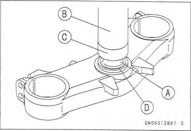

14-8
STEERING
Steering
Stem
Settle
the bearings in place as follows:
O
Tighten the steering stem nut with 20 Nm (2.0 kgf-m, 14.5 ft-lb) of
torque first, and loosen it a fraction of a turn until it turns
lightly. (To tighten the stem nut to the specified torque, hook the
wrench on the stem nut, and pull the wrench at the hole by 11.1 kg
(24.5 lb) [B] force in the direction shown.) Afterward tighten it
again with specified torque using a special tool [A].
Install
the lock washer so that claw of washer fit the notch of steering
stem nut.
First
tighten the steering stem lock nut by hand until the resistance is
felt fully, then tighten the steering stem nut additional more than
two notches so that align the notch of stem and stem lock nuts with
specified torque.
o
Check that there is no play and the steering stem turns smoothly
without rattles. If not, the steering stem bearing may be damaged.
O
Again back out the stem lock nut a fraction of turn until it turns
lightly.
Turn
the stem lock nut lightly clockwise until it just becomes hard
to turn. Do not overtighten, or the steering will be too tight.
Bend
the claw of lock washer to steering stem lock nut notch.
Special
Tool - Steering Stem Nut Wrench: 57001-1100 [A]
Torque
- Steering Stem Nut: 20 N m (2.0 kgf-m, 14.5 ft-lb)
Install
the stem head.
Install
the washer, and tighten the stem head nut with specified torque.
Install
the front fork (see Suspension chapter).
NOTE
O
Tighten
the fork upper clamp bolts first, next the stem head nut, last the
fork lower clamp bolts.
O
Tighten
the two lower fork clamp bolts alternately two times to ensure even
tightening torque.
Torque
- Steering Stem Head Nut : 78 N-m (8.0 kgf-m, 58 ft-lb)
Front
Fork Clamp Bolts (Upper) : 20 N-m (2.0 kgf-m, 14.5 ft-lb)
Front
Fork Clamp Bolts (Lower) : 20 N-m (2.0 kgf-m, 14.5 ft-lb)
Do
not impede the handlebar turning by routing the
cables,
harnesses and hoses improperly (see Ap-
pendix
chapter).
Stem
Bearing Lubrication
O
Refer to the Steering in the Periodic Maintenance chapter.
http://moto.amoti.rtt/

A warning
![]()
Steering
Stem
STEERING
14-9
Steering
Stem Warp
Whenever
the steering stem is removed, or if the steering can not be
adjusted for smooth action, check the steering stem for
straightness.
If
the steering stem [A] is bent, replace the steering stem.
http://moto.amoti.rtt/

14-10
STEERING
Handlebar
Handlebar
Removal •
Remove:
Clutch
Lever Assembly [A]
Left
Handlebar Switch Housing [B] Front Brake Master Cylinder [C] Right
handlebar Switch Housing [D] Throttle Case [E]
•
Remove:
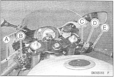
Weight Bolts [A] Handlebar Weight [B] Fitting [C]
Clip [D]
Remove:
Steering Stem Head [A] Throttle Grip Left Handlebar Grip Handlebar Bolts [B] Handlebar Position Bolt [C]
Remove the handlebars [D].

Handlebar Installation
Apply adhesive cement to the inside of the left handlebar grip.
Apply a non-permanent locking agent to the threads of the handlebar position bolts and weight bolts, and tighten them with specified torque.
Torque - Handlebar Bolts: 25 N-m (2.5 kgf-m, 187 in-lb)
Handlebar Position Bolts: 9.8 N-m (1.0 kgf-m, 87 in-lb)
Install the front brake master cylinder (see Brakes chapter).
Install the clutch lever [A] so that the mating surface [B] of the left handlebar switch housing is aligned with the mating surface [C] of the clutch lever clamp.
Torque - Clutch Lever Clamp Bolts: 7.8 N-m (0.80 kgf-m, 69 in-lb)
Handlebar Switch Housing Screws: 3.5 N-m (0.36 kgf-m, 31 in-lb)
Install the removed parts (see appropriate chapters).

http://moto.amoti.rtt/
FRAME
15-1
Frame
TABLE
OF CONTENTS
Exploded
View
Seats
Rear
Seat Removal
Rear
Seat Installation
Front
Seat Removal
Front
Seat Installation
Fairings
Lower
Fairing Removal
Inner
(Upper) Fairing Removal
Inner
(Lower) Fairing Removal
Upper
Fairing Removal
Seat
Cover
Seat
Cover Removal
Seat
Cover Installation
Fenders
Front
Fender Removal
Front
Fender Installation
Flap
and Rear Fender Rear Removal
Flap
and Rear Fender Rear Installation
Rear
Fender Front Removal
Rear
Fender Front Installation
Inner
Fender Removal
Inner
Fender Installation
Frame
Rear
Frame Removal
Rear
Frame Installation
Frame
Inspection
Storage
Box
Storage
Box Removal
Storage
Box Installation
Side
Stand
Side
Stand Removal
Side
Stand Installation
15-2
15-8
15-8
15-8
15-8
15-8
15-9
15-9
15-9
15-9
15-9
15-11
15-11
15-11
15-12
15-12
15-12
15-12
15-12
15-13
15-13
15-13
15-13
15-14
15-14
15-14
15-14
15-15
15-15
15-15
15-16
15-16
15-16
http://moto.amoti.rtt/
15-2
FRAME
Exploded
View
http://moto.amoti.rtt/
No. |
Fastener |
Torque |
Remarks |
||
Nm |
kgf-m |
ft'lb |
|||
1 |
Footpeg stay bolts |
25 |
2.5 |
18 |
|
2 |
Footpeg holder bolts |
34 |
3.5 |
25 |
L |
3 |
Rear frame bolts |
59 |
6.0 |
43 |
^ |
4 |
Side stand bracket bolts |
49 |
5.0 |
36 |
|
5 |
Side stand bolt |
44 |
4.5 |
32 |
G |
6 |
Side stand switch bolt |
8.8 |
0.90 |
78 in lb |
L |
G:
Apply grease.
L:
Apply a non-permanent locking agent.
http://moto.amoti.rtt/
15-4
FRAME
Exploded
View
http://moto.amoti.rtt/
No. |
Fastener |
Torque |
Remarks |
|||
N-m |
kgf-m |
ft-lb |
||||
1 |
Wind shield mounting screws |
0.4 |
0.04 |
3.5 in-lb |
|
|
2 |
Front fender mounting bolts |
2.9 |
0.30 |
26 in-lb |
L |
|
3.
United States and Canada Models L: Apply a non-permanent locking
agent.
http://moto.amoti.rtt/
15-6
FRAME
Exploded
View
http://moto.amoti.rtt/
FRAME
15-7
Exploded
View
1.
United States and Canada Models
http://moto.amoti.rtt/
15-8
FRAME
Seats
Rear
Seat Removal
•
Insert
the ignition switch key into the seat lock [A], turning
Rear Seat Installation
Slip the rear seat hooks [A] into the slend holes [B] on the frame.
Insert the seat pin [C] into the latch hole [D],
Push down the rear part of the seat until the lock clicks.

Front Seat Removal
Remove:
Rear Seat (see Rear Seat Removal)
Mounting Bolt [A]
Set Bracket (rear) [B]
Remove the front seat [C] by pulling the rear of it up and backward.
Front Seat Installation
• Slip the front seat hook [A] under the brace [B] of the seat
bracket (front).

http://moto.amoti.ru/
Fairings
FRAME
15-9
Lower
Fairing Removal
Remove:
Allen
Bolts [A] [B] [C] [D] [E]
Rivet
Screws [F]
Pull
the lower front part of the lower fairing outward to
clear
the stoppers [G].
Remove
the lower fairing.
Remove
the other side lower fairing in the same manner.
NOTE
O
When
removing the left and right lower fairings at the
same
time, do not remove the screws [D] (both sides)
and
bottom of stoppers [G],
Inner
(Upper) Fairing Removal
Remove
the alien bolts [A],
Pull
the inner (upper) fairing upward [B] to clear the stop-
pers
[C].
Inner
(Lower) Fairing Removal
•
Remove:
Lower
Fairing (Left or Right)
Other
Side Inner Fairing Bolt [A]
Inner
(Lower) Fairing [B]
Upper
Fairing Removal
•
Remove:
Inner
(Upper) Fairings [A]
Allen
Bolts [B] (Left and Right)
http://moto.amoti.ru/
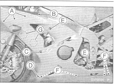

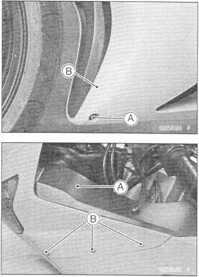
15-10
FRAME
•
Remove:Fairings
Nuts [A] (Left and Right)
Rear View Mirrors [B] (Left and Right)
• Remove:
Headlight Lead Connector [A]
Turn Signal Light Lead Connector [B] Upper Fairing


http://moto.amoti.rtt/
Seat
Cover
FRAME
15-11
Seat
Cover Removal
Remove:
Seats
Screws
and Washers [A]
Rivet
Screws [B] (Left and Right)
Pull
the seat cover backward to clear the stoppers [C],
Seat
Cover Installation
Set
the seat cover [A], and insert the rivet screws [B] into
the
holes in the seat cover and rear fender rear.
Screw
in the pins [C] into the rivet.
Fit
the projection [D] on the seat cover into the rear frame
bracket.
Tighten
the screws [E].
Install
the seats.
http://moto.amoti.rtt/

15-12
FRAME
Fenders
Front
Fender Removal
Remove:
Brake
Hose Clamps [A] (Left and Right)
Bolts
[B] (Left and Right)
Remove
the front fender [C].
Front
Fender Installation
Install
the front fender to the front fork.
Apply
a non-permanent locking agent to the thread of the
front
fender mounting bolts.
Tighten:
Torque
- Front Fender Mounting Bolts: 2.9 N-m (0.30 kgf-m,
26
in-lb)
Install
the brake hose clamps to the front fender holes.
Flap
and Rear Fender Rear Removal
Remove:
Seats
(see Rear/Front Seat Removal)
Seat
Cover (see Seat Cover Removal)
Storage
Box (see Storage Box Removal)
Disconnect:
Rear
Turn Signal Light Lead Connectors [A] (Left and
Right)
License
Light Lead Connector [B]
Tail/Brake
Light Lead Connector [C]
Remove:
Allen
Bolts [D]
Nuts
[E]
Seat
Lock Bolts [F]
Remove
the rivet screws [A] to take off the brackets [B]
and
flap [C] assembled the rear turn signals and license
light.
Pull
out the rear fender rear [D] assembled tail/brake light
downward.
Flap
and Rear Fender Rear Installation
http://moto.amoti.ru/


Insert the projection of rear fender rear under the rear fender front.
Install the front part of the flap under the rear fender rear.
Install the harness clamp in accordance with Harness Routing section in Appendix chapter.
Fenders
FRAME
15-13
Rear
Fender Front Removal
Remove:
Flap
Rear
Fender Rear
Battery
[A]
Junction
Box [B]
Starter
Relay Assy [C]
Turn
Signal Relay [D]
Fuel
Pump Relay [E]
ECU
Main Relay [F]
ECU
Fuse Holder [G]
Seat
Lock [H]
Remove
the bolts [I] and main harness clamp [J],
Pull
out the rear fender front downward.
Rear
Fender Front Installation
Install
the removed parts.
Run
the harness correctly (see Appendix chapter).
Inner
Fender Removal
Remove:
Allen
Bolts (Left and Right) [A]
Brake
Hose Clamp [B]
Pull
out the inner rear fender from the swingarm.
Inner
Fender Installation
Insert
the projections of the inner fender to the swingarm.
Tighten
the alien bolts (left and right).
Insert
the brake hose clamp to the inner fender hole.
http://moto.amoti.rtt/


15-14
FRAME
Frame
Rear
Frame Removal
•
Remove:
Fuel
Tank (see Fuel System (DFI) chapter)
Flap
and Rear Fender Rear (see Flap and Rear Fender
Rear
Removal)
Rear
Fender Front (see Rear Fender Front Removal)
Clamps
for Main Harness
Frame
Bolts and Nuts [A]
Rear
Step Bracket Bolts [B]
Rear
Frame Installation •
Tighten:
Torque
- Rear Frame Bolts and Nuts: 59 N-m (6.0 kgf-m, 43 ft-lb)
Rear
Step Brackets Bolts: 25 N-m (2.5 kgf-m, 19 ft-lb)
Frame
Inspection
Visually
inspect the frame for cracks, dents, bending, or
warp.
If
there is any damage to the frame, replace it.
A
repaired frame may fail in use, possibly causing
an
accident. If the frame is bent, dented, cracked,
or
warped, replace it.
http://moto.amoti.ru/
A warning

Storage
Box
FRAME
15-15
Storage
Box Removal
Remove:
Seat
Cover (see this chapter)
Screw
[A]
Pulling
up the rear part of the box backward.
Storage
Box Installation
Insert
the front part [A] of the box into the rear frame [B],
Tighten
the screws.
http://moto.amoti.rtt/

15-16
FRAME
Side
Stand
Side
Stand Removal
Raise
the rear wheel off the ground with the stand.
Disconnect
the side stand switch lead connectors.
Remove:
Side
Stand Switch Bolt [A]
Spring
[B]
Side
Stand Bolt [C]
Side
Stand [D]
Switch
Bracket Bolts [E]
Side
Stand Bracket Bolts [F]
Side
Stand Installation
Apply
grease to the sliding area [B] of the side stand [A]
and
thread of the side stand bolt [C].
Tighten
the bolt and lock them with the nut.
Torque
- Side Stand Bolt [C]: 44 N-m (4.5 kgf-m, 32 ft-lb)
Side
Stand Bracket Bolts [E]: 49 N-m (5.0 kgf-m,
36
ft-lb)
Hook
the spring so that face the long spring end upward.
Install
the switch bracket and side stand switch.
O
Apply a non-permanent locking agent to the thread of the switch
bracket bolt and switch bolt.
Torque
- Side Stand Switch Bracket Bolt [D]: 3.9 N-m (0.40 kgf-m, 35 in-lb)
Side
Stand Switch Bolt [F]: 8.8 N-m (0.90 kgf-m, 78 in-lb)
http://moto.amoti.rtt/


ELECTRICAL
SYSTEM 16-1
Exploded
View 16-4
Wiring
Diagram (United States and
Canada)
16-10
Wiring
Diagram (Australia) 16-12
Wiring
Diagram (Other than United
States,
Canada and Australia) 16-14
Specifications
16-16
Special
Tools and Sealant 16-17
Parts
Location 16-18
Precautions
16-20
Electrical
Wiring 16-22
Wiring
Inspection 16-22
Battery
16-23
Battery
Removal 16-23
Electrolyte
Filling 16-23
Initial
Charge 16-25
Precautions
16-25
Interchange
16-26
Charging
Condition Inspection 16-26
Refreshing
Charge 16-26
Charging
System 16-28
Alternator
Cover Removal 16-28
Alternator
Cover Installation 16-28
Stator
Coil Removal 16-28
Stator
Coil Installation 16-28
Alternator
Rotor Removal 16-29
Alternator
Rotor Installation 16-29
Alternator
Inspection 16-31
Regulator/Rectifier
Inspection 16-32
Charging
Voltage Inspection 16-35
Ignition
System 16-37
Crankshaft
Sensor Removal 16-38
Crankshaft
Sensor Installation 16-39
Crankshaft
Sensor Inspection 16-39
Crankshaft
Sensor Peak Voltage 16-40
Stick
Coil (Ignition Coil together with
Spark
Plug Cap) Removal 16-40
Stick
Coil (Ignition Coil together with
Spark
Plug Cap) Installation 16-40
Stick
Coil (Ignition Coil together with
Spark
Plug Cap) Inspection 16-41
Stick
Coil Primary Peak Voltage 16-41
Spark
Plug Removal 16-42
Spark
Plug Installation 16-42
Spark
Plug Cleaning and Inspection 16-42
Spark
Plug Gap Inspection 16-42
Camshaft
Position Sensor Removal 16-43 Camshaft Position Sensor
Installation
16-43
Camshaft
Position Sensor
Inspection
16-43
Camshaft
Position Sensor Peak
Voltage
Inspection 16-44
Interlock
Operation Inspection 16-45
IC
Igniter Inspection 16-46
Electric
Starter System 16-48
Starter
Motor Removal 16-48
Starter
Motor Installation 16-48
Starter
Motor Disassembly 16-48
Starter
Motor Assembly 16-49
Brush
Inspection 16-50
Commutator
Cleaning and
Inspection
16-50
Armature
Inspection 16-51
Brush
Lead Inspection 16-51
Right-hand
End Cover Assembly
Inspection
16-51
Starter
Relay Inspection 16-52
Lighting
System 16-54
Headlight
Beam Horizontal Vertical
Adjustment
16-54
Headlight
Bulb Replacement 16-55
Turn
Signal Relay Inspection 16-57
Radiator
Fan System 16-59
Fan
System Circuit Inspection 16-59
Fan
Motor Inspection 16-59
Meter
16-61
Meter
Assembly Removal 16-61
Meter
Assembly Disassembly 16-61
Meter,
Gauge, Indicator Unit 16-62
Electronic
Combination Meter
Assembly
Inspection 16-62
Switches
and Sensors 16-71
Brake
Light Timing Inspection 16-71
http://moto.amoti.rtt/Electrical System table of contents
16-2
ELECTRICAL SYSTEM
Brake
Light Timing Adjustment 16-71
Switch
Inspection 16-71
Radiator
Fan Switch Inspection 16-72
Water
Temperature Sensor
Inspection
16-73
Speed
Sensor Removal 16-73
Speed
Sensor Installation 16-74
Speed
Sensor Inspection 16-74
Fuel
Reserve Switch Inspection (1). 16-74 Fuel Reserve Switch Inspection
(2). 16-75 Junction Box 16-76
Junction
Box Fuse Circuit
Inspection
16-76
Starter
Circuit/Headlight Relay
Inspection
16-76
Diode
Circuit Inspection 16-77
Fuse
16-79
30
A Main Fuse Removal 16-79
Junction
Box Fuse Removal 16-79
15A
ECU Fuse Removal 16-79
Fuse
Installation 16-79
Fuse
Inspection 16-80
http://moto.amoti.rtt/
http://moto.amoti.rtt/![]()

16-4
ELECTRICAL SYSTEM Exploded View
http://moto.amoti.rtt/
No. |
Fastener |
Torque |
Remarks |
||
N-m | kgf-m |
ft-lb |
||||
1 |
Crankshaft sensor cover bolts |
9.8 |
1.0 |
87 in-lb |
L (1) |
2 |
Spark plugs |
13 |
1.3 |
113 in-lb |
|
3 |
Crankshaft sensor bolts |
5.9 |
0.60 |
52 in-lb |
|
4 |
Timing rotor bolt |
44 |
4.5 |
33 |
|
5 |
Tail/Brake light mounting screws |
1.2 |
0.12 |
10 in-lb |
|
6 |
License light mounting screws |
1.2 |
0.12 |
10 in-lb |
|
7 |
License light assembly screws |
1.0 |
0.10 |
8.7 in-lb |
|
8 |
Camshaft position sensor bolt |
12 |
1.2 |
106 in-lb |
|
Camshaft
Position Sensor
Stick
Coils
Crankshaft
Sensor
ECU
(Electronic Control Unit)
Turn
Signal Relay
Fuel
Pump Relay
ECU
Main Relay
L:
Apply a non-permanent locking agent. SS: Apply silicone sealant.
http://moto.amoti.rtt/
16-6
ELECTRICAL SYSTEM
Exploded
View
http://moto.amoti.rtt/
No. |
Fastener |
Torque |
Remarks |
|||
N-m |
kgf-m |
ft-lb |
||||
1 |
Alternator cover bolt |
12 |
1.2 |
104 in-lb |
|
|
2 |
Alternator lead holding plate bolts |
6.9 |
0.70 |
61 in-lb |
L |
|
3 |
Stator coil bolts |
12 |
1.2 |
110 in-lb |
L |
|
4 |
Alternator rotor bolt |
120 |
12 |
87 |
|
|
5 |
Fuel pump bolts |
9.8 |
1.0 |
87 in-lb |
S |
|
6 |
Neutral switch |
15 |
1.5 |
11 |
|
|
7 |
Oil pressure switch |
15 |
1.5 |
11 |
SS |
|
8 |
Oil pressure switch terminal bolt |
1.5 |
0.15 |
13 in-lb |
G |
|
9 |
Front brake light switch screw |
1.2 |
0.12 |
10 in-lb |
|
|
10 |
Handlebar switch housing screws |
3.5 |
0.36 |
31 in-lb |
|
|
11 |
Starter motor mounting bolts |
9.8 |
1.0 |
87 |
L |
|
I 12 |
Starter motor clutch bolts |
33 |
3.4 |
24 |
L |
|
Fuel
Pump
Regulator/Rectifier
Starter
Lockout Switch
Front
Brake Light Switch
Starter
Relay
Main
Fuse
California
Model
L:
Apply a non-permanent locking agent. SS: Apply silicone sealant.
M:
Apply molybdenum disulfide grease.
G:
Apply grease or engine oil.
S:
Follow the specified tightening sequence.
http://moto.amoti.ru/
16-8
ELECTRICAL SYSTEM
Exploded
View
fiP0207«B*S
C
http://moto.amoti.ru/
No. |
Fastener |
Torque |
Remarks |
|||
N-m |
kgf-m |
ft lb |
||||
1 |
Fan switch |
18 |
1.8 |
13 |
|
|
2 |
Water temperature sensor |
25 |
2.5 |
18 |
L |
|
3 |
Side Stand Switch Bolt |
8.8 |
0.90 |
78 in-lb |
L |
|
4 |
Meter screws |
1.2 |
0.12 |
10 in-lb |
|
|
5 |
Meter assembly screws |
1.2 |
0.12 |
10 in lb |
|
|
6 |
Engine Ground Lead Terminal Bolt |
9.8 |
1.0 |
87 in-lb |
||
Junction
Box
Speed
Sensor
Vehicle-down
Sensor
Side
Stand Switch
Rear
Brake Light Switch
Air
Temperature Sensor
L:
Apply a non-permanent locking agent.
http://moto.amoti.ru/
16-10
ELECTRICAL SYSTEM
Wiring
Diagram (United States and Canada)
http://mofo.amofi.ru/
ELECTRICAL
SYSTEM 16-11
Wiring
Diagram (United States and Canada)
http://mofo.amofi.ru/


16-12
ELECTRICAL SYSTEM Wiring Diagram (Australia)
Emin.
s"*rk
Plm.
K2L1157BW5
C
http://mofo.amofi.ru/
![]()
ELECTRICAL
SYSTEM 16-13
Wiring
Diagram (Australia)
http://mofo.amofi.ru/


16-14
ELECTRICAL SYSTEM
Wiring
Diagram (Other than United States, Canada and Australia)
http://moto.amoti.ru/
ELECTRICAL SYSTEM 16-15
Wiring
Diagram (Other than United States, Canada and Australia)
http://mofo.amofi.ru/
Item |
Standard |
Battery: Type Capacity Voltage |
Sealed Battery 12 V 8 Ah 12.6 V or more |
Charging System: Type Alternator output voltage Stator coil resistance |
Three-phase AC 42.4 ~ 63.6 V @4 000 r/min (rpm) 0.3 ~ 0.4 o |
Charging voltage (regulator/rectifier output voltage) |
14.2 ~ 15.2 V |
Ignition System: Crankshaft sensor resistance Crankshaft sensor peak voltage Camshaft Position Sensor Resistance Camshaft Position Sensor Peak Voltage Interlock Operation Voltage Stick coil: |
460 ~470 n 2.0 V or more 490 ~ 590 Q 0.135 V or more 4 V or more |
Primary winding resistance Secondary winding resistance Primary peak voltage |
1.2 ~ 1.6 Q 8.5 ~ 11.5 kfi 100 V or more |
Electric Starter System: Starter motor: Brush length Commutator diameter Switch and Sensor: |
7 mm (0.28 in.), Service Limit 3.5 mm (0.14 in.) 24 mm (0.94 in.), Service Limit 23 mm (0.91 in.) |
Rear brake light switch timing Engine oil pressure switch connections Fan switch resistance: |
ON after about 10 mm (0.39 in) pedal travel When engine is stopped: ON When engine is running: OFF |
Rising temperature Falling temperature Water temperature sensor resistance |
From OFF to ON @ 93 - 103°C (199 ~ 217°F) Fan stops with the temperature 3 ~ 8CC (38 ~ 46“F) lower than the operation temperature range. ON: Less than 0.5 fl OFF: More than 10 Mf> in the text |
http://mofo.amofi.rtt/
ELECTRICAL SYSTEM 16-17
Special
Tools and Sealant
Rotor
Puller, M17/M18/M20/M22 x 1.5 : 57001-1216
Flywheel
Holder : 57001-1313
Hand
Tester : 57001-1394
57001-1405
Lead
Wire - Peak Voltage Adapter : 57001-1449
57001-1457
57001-1542
Kawasaki
Bond (Silicone sealant): 56019-120
http://moto.amoti.rtt/


16-18
ELECTRICAL SYSTEM
Starter
Lockout Switch
Stick
Coils
Water
Temperature Sensor
Vehicle-down
Sensor
Battery
Junction
Box
ECU
(Electronic Control Unit)
Radiator
Fan Switch
Starter
Motor
Alternator
Neutral
Switch
Speed
Sensor
Side
Stand Switch
http://moto.amoti.rtt/Parts Location
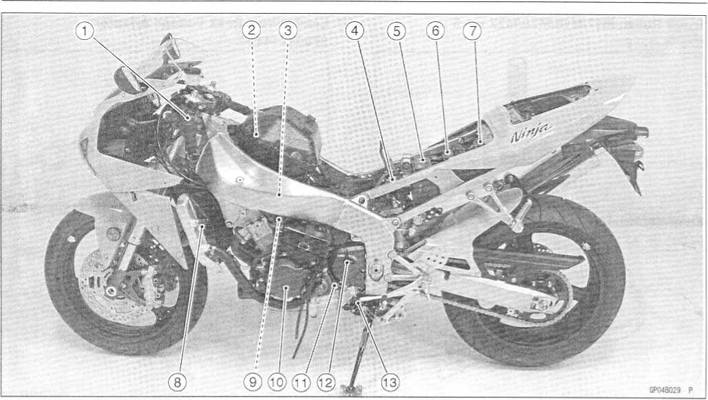
1. |
Starter Relay and Main Fuse |
7. Front Brake Light Switch |
2. |
Turn Signal Relay |
8. Rear Brake Light Switch |
3. |
Fuel Pump Relay |
9. Regulator/Rectifire |
4. |
ECU Fuse |
10. Crankshaft Sensor |
5. |
ECU Main Relay |
11. Oil Pressure Switch |
6. |
Inlet Air Pressure Sensor |
12. Camshaft Position Sensor |
http://moto.amoti.rtt/
BK |
Black |
G |
Green |
P |
Pink |
BL |
Blue |
GY |
Gray |
PU |
Purple |
BR |
Brown |
LB |
Light blue |
R |
Red |
CH |
Chocolate |
LG |
Light green |
W |
White |
DG |
Dark green |
0 |
Orange |
Y |
Yellow |
http://moto.amoti.rtt/
ELECTRICAL
SYSTEM 16-21
O
Electrical Connectors Female Connectors [A]
Male
Connectors [B]
http://moto.amoti.rtt/Precautions


16-22
ELECTRICAL SYSTEM
Electrical
Wiring
Wiring
Inspection
Visually
inspect the wiring for signs of burning, fraying,
etc.
If
any wiring is poor, replace the damaged wiring.
Pull
each connector [A] apart and inspect it for corrosion,
dirt,
and damage.
If
the connector is corroded or dirty, clean it carefully. If it
is
damaged, replace it.
Check
the wiring for continuity.
O
Use the wiring diagram to find the ends of the lead which
is
suspected of being a problem.
O
Connect the hand tester between the ends of the leads.
Special
Tool - Hand Tester: 57001-1394
o
Set the tester to the * 1 ft range, and read the tester.
★
If
the tester does not read 0 ft, the lead is defective. Replace
the lead or the wiring harness [B] if necessary.

http://moto.amoti.rtt/
ELECTRICAL
SYSTEM 16-23
Battery
Battery
Removal
Remove
the seats (see Frame chapter).
Disconnect
the negative (-) lead [A] and then positive (+)
lead
[B].
CAUTION ~
Be
sure to disconnect the negative (-) lead first.
Remove
the battery.
Electrolyte
Filling
CAUTION ~~
Do
not remove the aluminum seal sheet [A] sealing
the
filler ports [B] until just before use.
Be
sure to use the dedicated electrolyte container
for
correct electrolyte volume. *
•
Check
to see that there is no peeling, tears or holes in the seal sheet
on the top of the battery.
Place
the battery on a level surface.
Remove
the seal sheet.
NOTE
O
A
battery whose seal sheet has any peeling, tears, or holes, requires
a refreshing charge (initial charge).
Take
the electrolyte container out of the vinyl bag.
Detach
the seal caps [A] from the container.
NOTE
O
Do
not discard the seal caps because it is used as the battery plugs
later.
O
Do
not peel back or pierce the seals [B] on the container.
Place
the electrolyte container upside down aligning six seals with the
six battery filler ports.
• Push
the container down strongly enough to break the seals. Now the
electrolyte should start to flow into the battery.


NOTE
O Do not tilt the container as the electrolyte flow may be interrupted.


http://moto.amoti.ru/
16-24
ELECTRICAL SYSTEM
Battery
Make
sure air bubbles [A] are coming up from all six filler
ports.
O
Leave the container this way for 5 minutes or longer.
NOTE
O
If
no air bubbles are coming up from a filler port, tap [B]
the
bottom of the container two or three times. Never
remove
the container from the battery.
CAUTION ~
•
Fill
the electrolyte into battery until the container is completely
emptied.
Be
certain that all the electrolyte has flowed out.
Tap
the bottom the same way as above if there is any electrolyte left
in the container.
Now
pull the container gently out of the battery.
Let
the battery sit for 20 minutes. During this time, the electrolyte
permeates the special separators and the gas generated by chemical
reaction is released.
• Fit
the seal caps [A] tightly into the filler ports until the seal cap
is at the same level as the top of the battery.
NOTE
O Do not hammer. Press down evenly with both hands.


CAUTION
Once you install the seal caps after filling the battery, never remove it, nor add any water or electrolyte.
http://moto.amoti.rtt/
Condition requiring initial charge |
Charging method |
At low temperatures (lower than CFC) |
0.9 A x 2 - 3 hours |
Battery has been stored in high temperature and humidity. |
|
Seal has been removed, or broken - peeling, tear or hole. |
0.9 Ax 15 - 20 hours |
Battery as old as 2 years or more after manufacture. Battery manufacturing date is printed on battery top. Example) 12 10 93 T1 Day Month Year Mfg. location |
Note
1 : Terminal voltage - To measure battery terminal voltage, use a
digital voltmeter.
Precautions
No
need of topping-up
No
topping-up is necessary in this battery until it ends its life under
normal use. Forcibly prying off the
seal
cap to add water is very dangerous. Never do that.
Refreshing
charge
If
an engine will not start, a horn sounds weak, or lamps are dim, it
indicates the battery has been discharged. Give refresh charge for 5
to 10 hours with charge current shown in the specification (see the
this chapter).
When
a fast charge is inevitably required, do it following precisely the
maximum charge current and time conditions indicated on the battery.
CAUTION
This
battery is designed to sustain no unusual deterioration if
refresh-charged according to the method specified above. However,
the battery’s performance may be reduced noticeably if
charged under conditions other than given above.
Never
remove the seal cap during refresh charge.
When
you do not use the motorcycle for months
Give
a refresh charge before you store the motorcycle and store it with
the negative lead removed. Give a refresh charge once a month
during storage.
Battery
life
If
the battery will not start the engine even after several refresh
charges, the battery has exceeded its useful life. Replace it.
(Provided, however, the vehicle's starting system has no problem.)
Keep
the battery away from sparks and open flames during charging, since
the battery gives off an explosive gas mixture of hydrogen and
oxygen. When using a battery charger, connect the battery to the
charger before turning on the charger. This procedure prevents
sparks at the battery terminals which could ignite any battery
gases.
No
fire should be drawn near the battery, or no terminals should have
the tightening loosened.
The
electrolyte contains sulfuric acid. Be careful not to have it touch
your skin or eyes. If touched, wash it off with liberal amount of
water. Get medical attention if severe.
http://moto.amoti.ru/
16-26
ELECTRICAL SYSTEM
Battery
Interchange
A
sealed battery can fully display its performance only when combined
with a proper vehicle electric
system.
Therefore, replace a sealed battery only on a motorcycle which was
originally equipped with
a
sealed battery.
Be
careful, if a sealed battery is installed on a motorcycle which had
an ordinary battery as original
equipment,
the sealed battery’s life will be shortened.
Charging
Condition Inspection
Battery
charging condition can be checked by measuring
battery
terminal voltage.
Remove
the seats (see Frame chapter).
Disconnect
the battery leads.
CAUTION
Be
sure to disconnect the negative (-) lead first.
Measure
the battery terminal voltage.
NOTE
O
Measure
with a digital voltmeter [A] which can be read
to
one decimal place voltage.
★
If
the reading is below the specified, refreshing charge is
If by chance an excessive amount of gas is generated due to overcharging, the safety valve operates to keep the battery safe.
A warning

Battery Terminal Voltage Standard: 12.6 V or more
Refreshing Charge
Remove the battery [A],
Do refresh-charge by following method according to the battery terminal voltage.
A warning
This battery is sealed type. Never remove seal caps [B] even at charging. Never add water. Charge with current and time as stated below.

0 25 50 75 100
Battery Charge(X)
K X =H
Refreshing Charge -
. . . bood
is required.
GP080I09S1 c

GP03011 OS 1 C
Terminal Voltage: 11.5 ~ less than 12.6 V Standard Charge
0.9 A x 5 ~ 10 h (see following chart)
Quick Charge
A x 1.0 h
CAUTION ~
If possible, do not quick charge. If the quick charge is done due to unavoidable circumstances, do standard charge later on.

Terminal Voltage : less than 11.5 V Charging Method : 0.9 A x 20 h
http://mofo.amofi.rtt/
Criteria |
Judgement |
12.6 V or higher |
Good |
12.0 - 12.6 V or lower |
Charge insufficient -» Recharge |
12.0 V or lower |
Unserviceable -» Replace |
http://moto.amoti.rtt/
16-28
ELECTRICAL SYSTEM
Charging
System
Alternator
Cover Removal
Remove:
Left
Lower Fairing (see Frame chapter)
Fuel
Tank (see Fuel System (DFI) chapter)
Coolant
Reserve Tank [A]
Alternator
Lead Connector [B]
Place
a suitable container under the alternator cover [C], and remove the
cover.
Alternator
Cover Installation
Apply
silicone sealant to the alternator lead grommet and
crankcase
halves mating surface [A] on the front and rear
sides
of the cover mount.
Sealant
- Kawasaki Bond (Silicone Sealant): 56019-120
Check
that knock pins [B] are in place on the crankcase.
Install
a new gasket and the alternator cover.
Tighten:
Torque
- Alternator Cover Bolts: 12 Nm (1.2 kgf-m, 104 in-lb)
Stator
Coil Removal
Remove:
Alternator
Cover (see Alternator Cover Removal)
Holding
Plate Bolts [A] and Plate
Alternator
Lead Grommet [B]
Stator
Coil Bolts [C]
Remove
the stator coil [D] from the alternator cover.
Stator
Coil Installation
Apply
a non-permanent locking agent to the threads of the stator coil
bolts and tighten them.
Torque
- Stator Coil Bolts: 12 N m (1.2 kgf-m, 110 in-lb)
Apply
silicone sealant to the circumference of the alternator lead
grommet, and fit the grommet into the notch of the cover securely.
Sealant
- Kawasaki Bond (Silicone Sealant): 92104-1063
Secure
the alternator lead with a holding plate, and apply a non-permanent
locking agent to the threads of the plate bolts and tighten them.
Torque
- Alternator Lead Holding Plate Bolts: 6.9 N-m (0.70 kgf-m, 61
in-lb)
Install
the alternator cover (see Alternator Cover Installation).
http://moto.amoti.ru/


Charging
System
ELECTRICAL
SYSTEM 16-29
Alternator
Rotor Removal
Remove:
Alternator
Cover (see Alternator Cover Removal)
Starter
Idle Gear and Shaft
Wipe
oil off the outer circumference of the rotor.
Hold
the alternator rotor steady with the flywheel holder
[A],
and remove the rotor bolt [B],
Special
Tool - Flywheel Holder: 57001-1313
•
Using
the flywheel puller [A] and rotor puller [B], remove
Special Tools - Flywheel Puller, M38 x 1.5: 57001-1405
Rotor Puller, M16/M18/M20/M22 x 1.5; 57001-1216
CAUTION * •
Do not attempt to strike the alternator rotor itself. Striking the rotor can cause the magnets to lose their magnetism.

Alternator Rotor Installation
Using a cleaning fluid, clean off any oil or dirt on the following portions and dry them with a clean cloth.
Crankshaft Tapered Portion
Alternator Rotor Tapered Portion
• Apply a thin coat of molybdenum disulfide grease to the crankshaft [C],
Install the starter gear [A], and washer [B],
Again, clean the crankshaft tapered portion [C] and dry there.

http://moto.amoti.rtt/
16-30
ELECTRICAL SYSTEM
Charging
System
•
Install
the alternator rotor [A] while turning [B] it counterclockwise.
Install the washer [A],
NOTE
O Confirm the alternator rotor fit or not to the crankshaft before tightening it with specified torque.
O Alternator bolt fastening process has two steps. If both steps are not carried out, the alternator bolt could loosen and the engine could be damaged. Carry out following two steps without fail.
Step 1:
Install the rotor and tighten it with 70 Nm (7 kgf-m, 52 ft-lb) of torque.
Remove the washer and rotor bolt.
Check the tightening torque with rotor puller.
If the rotor is not pulled out with 40 N m (4.1 kgf-m, 30 ft-lb) of drawing torque, it is installed correctly.
If the rotor is pulled out with under 40 Nm (4.1 kgf-m, 30 ft-lb) of drawing torque, clean off any oil dirt or flaw of the crankshaft and rotor tapered portion, and dry them with a clean cloth. Then, confirm that it is not pulled out with above torque.
Tighten the alternator rotor bolt [B] while holding the alter- nator rotor steady with the flywheel holder.
Special Tool - Flywheel Holder: 57001-1313

Torque - Alternator Rotor Bolt: 120 N-m (12 kgf-m, 87 ft-lb)
Step 2:
Loosen the alternator rotor bolt until turn it by hand.
Tighten the alternator rotor bolt again while holding the alternator rotor steady with the flywheel holder.
Observe the tightening torque. If tightening torque is over the specified torque, damaged the alternator rotor bolt. Special Tool - Flywheel Holder: 57001-1313
Torque - Alternator Rotor Bolt: 120 N-m (12 kgf-m, 87 ft-lb)
http://moto.amoti.rtt/
Tester |
Connections |
Reading |
|
Range |
Tester (+) to |
Tester (-) to |
@ 4 000 rpm |
250 V |
One Black |
Another |
42.4 - |
AC |
lead |
Black lead |
63.6 V |
http://moto.amoti.rtt/
Tester |
Connections |
Reading |
|
Range |
Tester (+) to |
Tester (-) to |
|
X 1 [) |
One Black |
Another |
0.3 ~ 0.4 n |
|
lead |
Black lead |
|
If
there is more resistance than shown in the table, or no tester
reading (infinity) for any two leads, the stator has an open lead
and must be replaced. Much less than this resistance means the
stator is shorted, and must be replaced.
Using
the highest resistance range of the hand tester, measure the
resistance between each of the black leads and chassis ground.
★Any
hand tester reading less than infinity (cc) indicates a short,
necessitating stator replacement.
If the stator coils have normal resistance, but the voltage check showed the alternator to be defective; then the rotor magnets have probably weakened, and the rotor must be replaced.
Regulator/Rectifier Inspection • Remove:
Seat Cover (see Frame chapter) Fuel Tank (see fuel System chapter) Connectors [A] (disconnect)
Clamp [B]

http://moto.amoti.rtt/
No. |
Connections |
Reading |
Tester Range |
|
Tester (+) |
Tester (-) |
|||
1 |
BK1 |
|
|
|
2 |
BK2 |
BK/BL |
oc |
|
3 |
BK3 |
|
|
|
4 |
BK1 |
|
|
|
5 |
BK2 |
BK/W |
|
|
6 |
BK3 |
|
|
x 1012 |
7 |
|
BK1 |
1/2 scale |
or |
8 |
BK/BL |
BK2 |
or less |
x 10012 |
9 |
|
BK3 |
|
|
10 |
|
BK1 |
|
|
11 |
BK/W |
BK2 |
OC |
|
12 |
|
BK3 |
|
|
http://moto.amoti.ru/
16-34
ELECTRICAL SYSTEM
Charging
System
Regulator
Circuit Check:
To
test the regulator out of circuit, use three 12 V batteries and a
test light (12 V 3 ~ 6 W bulb in a socket with leads).
CAUTION ~
The
test light works as an indicator and also a current limiter to
protect the regulator/rectifier from excessive current. Do not
use an ammeter instead of a test light.
Do
the 1st step regulator circuit test.
O
Connect the test light and the 12 V battery to the
regula-
tor/rectifier
as shown.
O
Check BK1, BK2, and BK3 terminal respectively.
If
the test light turns on, the regulator/rectifier is
defective.
Replace
it.
If
the test light does not turn on, continue the test.
Do
the 2nd step regulator circuit test.
O
Connect the test light and the 12 V battery in the same
manner
as specified in the "1 st step regulator circuit test",
o
Apply 12 V to the BK/R terminal,
o
Check BK1, BK2, and BK3 terminal respectively.
If
the test light turns on, the regulator/rectifier is
defective.
Replace
it.
If
the test light does not turn on, continue the test.
Do
the 3rd step regulator circuit test
O
Connect the test light and the 12 V battery in the same
manner
as specified in the "1 st step regulator circuit test".
O
Momentarily apply 24 V to the BK/R terminal by adding a
12
V battery.
O
Check BK1, BK2, and BK3 terminals respectively. *
★
CAUTION
Do
not apply more than 24 volts. If more than 24 volts is applied the
regulator/rectifier may be damaged. Do not apply 24 V more than
a few seconds.
If
the test light did not light when the 24 V was applied momentarily
to the BK/R terminal, the regulator/rectifier is defective. Replace
it.
★ If
the regulator/rectifier passes all of the tests described, it may
still be defective. If the charging system still does not work
properly after checking all of the components and the battery, test
the regulator/rectifier by replacing it with a known good unit.


If 24 volts is applied for more than a few seconds, the regulator/rectifier may be damaged.

http://moto.amoti.ru/
Tester Range |
Connections |
Reading |
|
Tester (+) to |
Tester (-) to |
||
25 V DC |
Battery (+) |
Battery (-) |
14.2 ~ 15.2 V |
•
Turn
off the ignition switch to stop the engine, and disconnect the
hand tester.
If the charging voltage is kept between the values given in the table, the charging system is considered to be working normally.
If the charging voltage is much higher than the values specified in the table, the regulator/rectifier is defective or the regulator/rectifier leads are loose or open.
If the charging voltage does not rise as the engine speed increases, then the regulator/rectifier is defective or the alternator output is insufficient for the loads. Check the alternator and regulator/rectifier to determine which part is defective.
http://moto.amoti.rtt/

16-36
ELECTRICAL SYSTEM
Charging
System
Charging
System Circuit
©
©
GPO9053813
C
Ignition
Switch
Alternator
Regulator/Rectifier
Battery
Main
Fuse 30 A
Load
http://moto.amoti.rtt/
ELECTRICAL
SYSTEM 16-37
/
http://moto.amoti.rtt/
Ignition System
Ignition System Troubleshooting

16-38
ELECTRICAL SYSTEM
The
ignition system produces extremely high voltage. Do not touch
the spark plugs or stick coils while the engine is running, or you
could receive a severe electrical shock.
CAUTION
Do
not disconnect the battery leads or any other electrical connections
when the ignition switch is on, or while the engine is running. This
is to prevent IC igniter damage.
Do
not install the battery backwards. The negative side is grounded.
This is to prevent damage to the diodes and IC igniter.
Crankshaft
Sensor Removal •
Remove:
Fuel
Tank (see Fuel System chapter) Reserve Tank
Right
Lower Fairing (see Frame chapter) Crankshaft Sensor Lead Connector
[A] Side Stand Switch Lead Connector [B]
Neutral
Switch Lead Connector [A]
Crankshaft
Sensor Cover Oil Pressure Switch Terminal [A]
•
Remove
the crankshaft sensor [B] by taking off the crankshaft sensor
bolts [Cj.Ignition System
A warning

http://moto.amoti.rtt/
ELECTRICAL
SYSTEM 16-39
Crankshaft
Sensor Installation
Route
the crankshaft sensor lead correctly (see Cable, Wire, and Hose
Routing in Appendix chapter).
Tighten:
Torque
- Crankshaft Sensor Bolts: 5.9 N-m (0.60 kgf-m, 52 in-lb)
Apply
silicone sealant [A] to the crankshaft sensor lead grommet and
crankcase halves mating surface on the front and rear sides of the
crankshaft sensor cover mount. Sealant
- Kawasaki Bond (Silicone Sealant): 56019-120
Apply
a non-permanent locking agent to the threads of the crankshaft
sensor cover bolt [A],
Install
the clamps [B] and tighten the crankshaft sensor cover bolts.
Torque
- Crankshaft Sensor Cover Bolts: 9.8 Nm (1.0
kgf-m,
87 in-lb)
Install
the oil pressure switch terminal and tighten the terminal
bolt.
Torque
- Oil Pressure Switch Terminal Bolt: 1.5 N-m (0.15 kgf-m, 13 in-lb)
Apply
grease to the terminal.
Install
the other remove parts.
Crankshaft
Sensor Inspection
Remove:
Fuel
Tank (see Fuel System chapter)
Crankshaft
Sensor Lead Connector [A]
Set
the hand tester [B] to the * 100
ft
range and connect the (+) lead to the black lead [C] and (-)
lead to the black/yellow lead [D] in the connector [A],
Special
Tool - Hand Tester: 57001- 1394
If
there is more resistance than the specified value, the coil has an
open lead and must be replaced. Much less than this resistance
means the coil is shorted, and must be replaced.
Crankshaft
Sensor Resistance: 460 ~ 470 J2
•
Using
the highest resistance range of the tester, measure the resistance
between the crankshaft sensor leads and chassis ground.Ignition System


★Any tester reading less than infinity (x) indicates a short, necessitating replacement of the crankshaft sensor assembly.

http://moto.amoti.rtt/
16-40
ELECTRICAL SYSTEM
Crankshaft
Sensor Peak Voltage
Remove:
Fuel
Tank (see Fuel System chapter)
Crankshaft
Sensor Lead Connector
Set
the Hand Tester [B] to the x 10 V DC range, and connect it a
commercially available peak voltage adapter [E] as shown in the
diagram.
Connect
the black lead (-) of the Adapter to black/yellow lead [D] and red
lead (+) to black lead [C] in the crankshaft sensor connector [A],
Turn
the ignition switch and engine stop switch on.
Grasp
the clutch lever and pushing the starter button, turn the engine 4
~ 5 seconds with the transmission gear in neutral to measure the
crankshaft sensor peak voltage.
Repeat
the measurement 5 or more times.
Crankshaft
Sensor Peak Voltage Standard: 2.0 V or more
Special
Tool - Hand Tester: 57001-1394
Recommended
Tool-
Peak
Voltage Adapter Type: KEK-54-9-B Brand: KOWA SEIKI
Stick
Coil (Ignition Coil together with Spark Plug Cap) Removal
Remove
the air cleaner housing (see Fuel System chapter).
Disconnect
the stick coil connectors [A],
Pull
the stick coils [B] off the spark plugs.
CAUTION ~
Do
not pry the connector part of the coil while removing the coil.
Stick
Coil (Ignition Coil together with Spark Plug Cap) Installation
Install
the coil using the following steps.
O
Insert the coil [A] as shown being careful of the coil installation
direction.
O
Connect the connectors [B].
O
Stick coil connectors angle [C]: about 45"
CAUTION
Do
not tap the coil head while installing the coil.
http://moto.amoti.rtt/Ignition System


ELECTRICAL
SYSTEM 16-41
Stick
Coil (Ignition Coil together with Spark Plug Cap) Inspection
Remove
the stick coils (see this chapter).
Measure
the primary winding resistance [A] as follows.
O
Connect the hand tester between the coil terminals.
0
Set the tester to the * 1 V.
range, and read the tester.
Measure
the secondary winding resistance [B] as follows, o Connect the
tester between the plug terminal and (-) coil
terminal.
oSet
the tester to the * 1 kl> range and read the tester.
Primary
Windings: 1.2-1.6
S2
Secondary
Windings: 8.5-
11.5 kS2
If
the tester does not read as specified, replace the coil.
Stick
Coil Primary Peak Voltage
NOTE
o
Be
sure the battery is fully charged.
Remove
the stick coils (see this chapter), but do not remove the
spark plugs.
Measure
the primary peak voltage as follows.
O
Install the new spark plug [A] into each stick coil [B], and ground
them onto the engine.
O
Connect a commercially available peak voltage adapter [C] into the
hand tester [D] which is set to the x 250 V DC range.
o
Connect the adapter to the lead wire-peak voltage adapter [E] which
is connected between the stick coil connector and stick coil.
ECU
Recommended
Tool-
Peak
Voltage Adapter Type: KEK-54-9-B Brand: KOWA SEIKI
Special
Tools - Hand Tester: 57001-1394
Lead
Wire-Peak Voltage Adapter: 57001-1449
Primary
Lead Connection
Adapter
(R, +) to lead wire-peak voltage adapter (W) Adapter (BK, -) to lead
wire-peak voltage adapter (R)
http://moto.amoti.rtt/Ignition System
Ignition Coil Winding Resistance


16-42
ELECTRICAL SYSTEM
To
avoid extremely high voltage shocks, do not touch the spark plugs or
tester connections.
Turn
the ignition switch and the engine stop switch ON.
Pushing
the starter button, turn the engine 4 - 5 seconds with the
transmission in neutral to measure the primary peak voltage.
Repeat
the measurements 5 times for one stick coil.
Stick
Coil Primary Peak Voltage Standard: 100 V or more
Repeat
the test for the other stick coil.
Stick
Coils (see Stick Coil Inspection)
Crankshaft
Sensor (see Crankshaft Sensor Inspection) ECU (see Fuel System (DFI)
chapter)
Spark
Plug Removal
Remove:
Air
Cleaner Housing (see Fuel System chapter)
Stick
Coils
Remove
the spark plugs using the 16 mm plug wrench. Owner’s
Tool - Spark Plug Wrench, 16 mm: 92110-1146
Spark
Plug Installation
Owner’s
Tool - Spark Plug Wrench, 16 mm: 92110-1146
Tighten:
Torque
- Spark Plugs: 13 N-m (1.3 kgf-m, 113 in-lb)
Fit
the stick coils securely.
Spark
Plug Cleaning and Inspection O
Refer to the Electrical System in the Periodic Maintenance
chapter.
Spark
Plug Gap Inspection
O
Refer to the Electrical System in the Periodic Maintenance
chapter.
http://moto.amoti.ru/
Ignition System
A warning
If the reading is less than the specified value, check the following.
Insert the spark plug vertically into the plug hole with the plug [a] installed in the plug wrench [b],

ELECTRICAL
SYSTEM 16-43
Camshaft
Position Sensor Removal
Remove
the lower fairings (see Frame chapter).
Lift
the left side of the baffle plate and take out the camshaft
position sensor lead connector.
Remove
the left under side radiator bolt.
Move
the bottom of the radiator toward the front [A], and disconnect the
camshaft position sensor lead connector
[B].
•
Remove:
Ignition System
Camshaft Position Sensor Bolt [A] Camshaft Position Sensor [B]

GP10B180 P
Camshaft Position Sensor Installation • Apply grease or engine oil to the O-ring on the camshaft position sensor.
Tighten:
Torque - Camshaft Position Sensor Bolt: 12 Nm (1.2 kgf-m, 106 in-lb)
Camshaft Position Sensor Inspection
Remove:
Right Lower Fairing (see Frame chapter)
Camshaft Position Sensor Lead Connector (disconnect)
Set the hand tester to the * 10 fi range and connect it to the terminals.
Special Tool - Hand Tester: 57001-1394
If there is more resistance than the specified value, the sensor coil has an open lead and must be replaced. Much less than this resistance means the sensor coil is shorted, and must be replaced.

Camshaft Position Sensor Resistance: 490 ~ 590 P
• Using the highest resistance range of the tester, measure the resistance between the camshaft position sensor leads and chassis ground.
★Any tester reading less than infinity (°c) indicates a short, necessitating replacement of the camshaft position sensor.
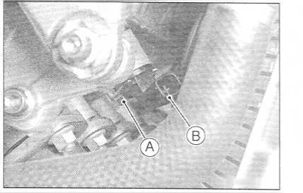
http://moto.amoti.rtt/
16-44
ELECTRICAL SYSTEM
Camshaft
Position Sensor Peak Voltage Inspection
Remove:
Right
Lower Inner Cover (see Frame chapter)
Camshaft
Position Sensor Lead Connector
Set
the commercially available tester [A] to the 10 V DC range.
Connect
commercially available peak voltage adapter [B] to the hand tester
and camshaft position sensor leads in the terminals.
Recommended
Tool-
Peak
Voltage Adapter Type: KEK-54-9-B Brand: KOWA SEIKI
Connections:
Camshaft Position Sensor Terminal
(+)
[C] H
[D]
<r-
<—
Adapter
Red
Black
Hand
Tester
(+)
{-)
Turn
the ignition switch and engine stop switch on.
Pushing
the starter button, turn the engine 4 ~ 5 seconds with the
transmission gear in neutral to measure the camshaft position
sensor peak voltage.
Repeat
the measurement 5 or more times.
Camshaft
Position Sensor Peak Voltage Standard: 0.1 V or more
★
If
the peak voltage is lower than the standard, inspect the camshaft
position sensor.Ignition System

http://moto.amoti.rtt/
ELECTRICAL
SYSTEM 16-45
Interlock
Operation Inspection
Remove
the seats (see Frame chapter).
Measure
the terminal voltage of the G/BK lead in the junction box
connector [A] in accordance with the following procedure.
O
Set the tester [B] to the 25 V DC range, connect it to the G/BK lead
and frame ground [C],
Connection:
Tester
(+) Terminal G/BK Lead Terminal Tester (-) Terminal ->• Frame
Ground
Condition:
Transmission
Gear 1st Position Clutch Lever Release Side Stand -» Down
OTurn
the ignition switch on. o Read the voltage.
If
the voltage is lower than the standard, inspect the side stand
switch, starter lockout switch and junction box. And their parts
are normality, replace the ECU.
If
the voltage is standard, push the starter button to check as
follows.
O
If the starter motor does not turn, the ECU is good, and check the
starter system circuit.
O
If the starter motor turned, ECU is defective. Replace the ECU.
http://moto.amoti.rtt/Ignition System
1St Check
Interlock Operation Voltage Standard: 4 V or more

16-46
ELECTRICAL SYSTEM
Raise
the rear wheel off the ground with a stand. • Set the following
conditions.
Condition:
Transmission
Gear -» 1st Position Clutch Lever ->• Release Side Stand ->
Up
Turn
the ignition switch on and push the starter button.
If
turn the engine, inspect the starter lockout switch, side stand
switch and junction box.
If
their parts are normality, replace the ECU
Set
the following conditions.
Condition:
Transmission
Gear -» 1st Position Clutch Lever -» Pull in Side Stand -> Up
Turn
the ignition switch on and push the starter button.
If
the engine dose not turn, inspect the starter lockout switch, side
stand switch and junction box.
If
their parts are normality, replace the ECU.
Inspect
the engine for its secure stop after the following operations are
completed.
Run
the engine to the following conditions.
Condition:
Transmission
Gear -> 1st Position Clutch Lever -> Release Side Stand -►
Up
Set
the side stand on the ground, then the engine will stop.
If
engine does not be stop, inspect the starter lockout switch, side
stand switch and junction box.
If
their parts are normality, replace the ECU.
1C
Igniter Inspection
oThe
1C igniter is built in the ECU [A],
•
Refer
to the Interlock Operation Inspection, Ignition System
Troubleshooting chart and Fuel System (DFI) chapter for ECU
Inspection.Ignition System
2Nd Check

http://moto.amoti.rtt/
ELECTRICAL
SYSTEM 16-47
Ignition
Switch
Engine
Stop Switch
Starter
Button
Stick
Coils
Spark
Plugs
Subthrottle
Motor
Crankshaft
Sensor 10. Side Stand Switch
Subthrottle
Sensor
Starter
Lockout Switch
ECU
Main Relay
ECU
Fuse 15A
Vehicle-down
Sensor
Battery
Main
Fuse 30A
ECU
(Electronic Control Unit)
http://moto.amoti.ru/


Ignition System
Ignition System Circuit

16-48
ELECTRICAL SYSTEM
Electric
Starter System
Starter
Motor Removal
Remove
the fuel tank (see Fuel System (DFI) chapter).
Slide
back the rubber cap.
Remove
the starter motor terminal bolt [A] and the mounting bolts
[B],
Pull
out the starter motor [C],
Starter
Motor Installation
CAUTION
Do
not tap the starter motor shaft or body. Tapping the shaft or body
could damage the motor.
•
When
installing the starter motor, clean the starter motor legs [A]
and crankcase [B] where the starter motor is grounded.


Replace the O-ring [A] with a new one.
Apply grease to the O-ring.
Tighten:
Torque - Starter Motor Mounting Bolts: 9.8 Nm (1.0 kgf-m, 87 in-lb)
Starter Motor Disassembly
• Take off the starter motor through bolts [A] and remove both end covers [B] and pull the armature out of the yoke [C].

http://mofo.amofi.rtt/
Electric
Starter System
ELECTRICAL
SYSTEM 16-49
Starter
Motor Assembly
Apply
a thin coat of grease to the oil seal [A],
Fit
the toothed washer [B] into the left-hand end cover.
Install
the washer [C].
Press
the springs and holding the brush leads with suitable clips
[A] as shown.
Put
the armature [B] among the brushes.
•
Install
the O-rings [A] as shown.

• Align the groove [A] in the right-hand end cover and the hollow mark [B] on the yoke.

http://moto.amoti.ru/
16-50
ELECTRICAL SYSTEM
Electric
Starter System
•
Align
the hollow mark [A] on the left-hand end cover and the hollow mark
[B] on the yoke.

Brush Inspection
Measure the length [A] of each brush.
If any is worn down to the service limit, replace the brush holder assembly.
Starter Motor Brush Length Standard: 7 mm (0.28 in.)
Service Limit: 3.5 mm (0.14 in.)

Commutator Cleaning and Inspection • Smooth the commutator surface [A] if necessary with fine emery cloth [B], and clean out the grooves. •
• Measure the diameter [A] of the commutator [B],
If the commutator diameter is less than the service limit, replace the starter motor with a new one .
Commutator Diameter
Standard: 24 mm (0.94 in.)
Service Limit: 23 mm (0.91 in.)


http://moto.amoti.rtt/
ELECTRICAL
SYSTEM 16-51
Electric
Starter System
Armature
Inspection
Using
the * 1 ft hand tester range, measure the resistance between
any two commutator segments [A], Special
Tool - Hand Tester: 57001-1394
If
there is a high resistance or no reading (oo)
between
any two segments, a winding is open and the starter motor must be
replaced.
Using
the highest hand tester range, measure the resistance between
the segments and the shaft [B],
If
there is any reading at all, the armature has a short and the
starter motor must be replaced.
NOTE
O
Even
if the foregoing checks show the armature to be good, it may be
defective in some manner not readily detectable with the hand
tester. If all other starter motor and starter motor circuit
components check good, but the starter motor still does not turn
over or only turns over weakly, replace the starter motor with a new
one.
Brush
Lead Inspection
Using
the * 1 Q
hand tester range, measure the resistance as shown.
Terminal
Bolt and Positive Brush
Right-hand
End Cover and Negative Brush Special
Tool - Hand Tester: 57001-1394
If
there is not close to zero ohms, the brush lead has an open.
Replace the positive brush assembly and/or the negative brush
subassembly.
Right-hand
End Cover Assembly Inspection
Using
the highest hand tester range, measure the resistance as
shown.
[A]
Terminal and Right-hand End Cover Special
Tool - Hand Tester: 57001-1394
If
there is any reading, the right-hand end cover assembly have a
short. Replace the right-hand end cover assembly.
http://moto.amoti.rtt/


16-52
ELECTRICAL SYSTEM
Electric
Starter System
Starter
Relay Inspection •
Remove:
Seats
(see Frame chapter) Starter Cable [A]
Battery
Cable [B] Connector [C]
Starter
Relay [D]
Connect
the hand tester [A] and 12 V battery [B] to the starter relay [C]
as shown.
Special
Tool - Hand Tester: 57001-1394
If
the relay does not work as specified, the relay is defective.
Replace the relay.
Testing
Relay
Tester
Range: * 1 range
Criteria: When
battery is connected -> 0 fi
When
battery is disconnected ->
x fl
http://moto.amoti.ru/


ELECTRICAL
SYSTEM 16-53
Electric
Starter System
Electric
Starter Circuit
Engine
Stop Switch
Starter
Button
Junction
Box
Starter
Circuit Relay
Side
Stand Switch
Neutral
Switch
Starter
Lockout Switch 10. Starter Motor
Starter
Relay
Main
Fuse 30 A
Battery
http://moto.amoti.rtt/
16-54
ELECTRICAL SYSTEM
Lighting
System
This
motorcycle adopt the daylight system and have a headlight relay in
the junction box. The headlight does not go on when the ignition
switch and the engine stop switch are first turned on. The headlight
comes on after the starter button is released and stays on until the
ignition switch is turned off. The headlight will go out momentarily
whenever the starter button is pressed and come back on when the
button is released.
Headlight
Beam Horizontal Vertical Adjustment
Remove
the inner (upper) fairing (see Frame chapter).
Turn
the horizontal adjuster [A] on the headlight in or out
until
the beam points straight ahead.
Turn
the vertical adjusters [B] on the headlight in or out to
adjust
the headlight vertically.
NOTE
O
On
high beam, the brightest points should be slightly below horizontal
with the motorcycle on its wheels and the rider seated. Adjust the
headlight(s) to the proper angle according to local regulations.
O
For
US model, the proper angle is 0.4 degrees below horizontal. This is
50 mm (2 in.) drop at 7.6 m (25 ft) measured from the center of the
headlights with the motorcycle on its wheels and the rider seated.
50
mm (2 in.) [A]
Center
of Brightest Spot [B]
7.6
m (25 ft) [C]
Height
of Headlight Center [D]
Low
Beam [E]
High
Beam [F]
http://moto.amoti.rtt/


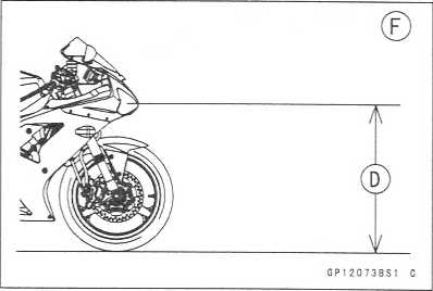
ELECTRICAL
SYSTEM 16-55
Lighting
System
Headlight
Bulb Replacement •
Remove:
Headlight
Bulb Dust Cover Headlight Connector [A]
Hook
[B]
Headlight
Bulb [C]
CAUTION ~
When
handling the quartz-halogen bulb, never touch the glass portion with
bare hands. Always use a clean cloth. Oil contamination from hands
or dirty rags can reduce bulb life or cause the bulb to explode. *
•
NOTE
O
Clean
off any contamination that inadvertently gets on the bulb with
alcohol or soap and water solution.
Replace
the headlight bulb.
• Align
the mark [A] on the headlight and mark [B] the dust cover, and turn
the dust cover clockwise so that the mark [B] faces topward.


After installation, adjust the headlight aim (see this chapter).

http://moto.amoti.ru/
16-56
ELECTRICAL SYSTEM Lighting System
Headlight/Tail
Light Circuit
Ignition
Switch
Headlight
(High Beam)
Headlight
(Low Beam)
City
Light
Main
Fuse 30A
Battery
License
Plate Light
Tail
Light
Tail
Light Fuse 10A
Headlight
Fuse 10A
Junction
Box
A:
Other than United States, Canadian and Australian Models B: Other
than United States and Canadian Models
http://moto.amoti.rtt/
Load |
Flashing times (c/m*) |
|
The Number of Turn Signal Lights |
Wattage (W) |
|
a ** |
21 |
140 - 250 |
2 |
42 |
75 - 95 |
(*):
Cycle(s) per minute
(**):
Correspond to “one light burned out"
http://moto.amoti.ru/
16-58
ELECTRICAL SYSTEM Lighting System
CD
©
0c„‘/(=[X1=b'/.
-BK/Y-
-BK/Y-
l)
®
I
10
GP120548*3
C
Turn
Signal Indicator Lights (Right & Left)
Front
Right Turn Signal Light
Front
Left Turn Signal Light
Turn
Signal Switch
Turn
Signal Relay
Junction
Box
Turn
Signal Relay Fuse 10A
Ignition
Switch
Rear
Right Turn Signal Light
Rear
Left Turn Signal Light
Main
Fuse 30 A
Battery
http://moto.amoti.rtt/Turn Signal Light Circuit
[Q) <**
■

![]()
ELECTRICAL
SYSTEM 16-59
Radiator
Fan System
The
radiator fan is connected directly to the battery. The fan may
start even if the ignition switch is off. NEVER TOUCH THE RADIATOR
FAN UNTIL THE RADIATOR FAN CONNECTOR IS DISCONNECTED. TOUCHING THE
FAN BEFORE THE CONNECTOR IS DISCONNECTED COULD CAUSE INJURY FROM THE
FAN BLADES. *
•
Fan
System Circuit Inspection
Remove
the left lower fairing (see Frame chapter)
Disconnect
the leads from the radiator fan switch [A],
Using
an auxiliary wire [B], connect the radiator fan switch leads.
If
the fan rotates, inspect the fan switch.
If
the fan does not rotate, inspect the following.
Leads
and Connectors Main Fuse and Fan Fuse Fan Motor
Fan
Motor Inspection
Remove
the left lower fairing (see Frame chapter).
• Disconnect
the 2-pin connector [A] in the fan motor leads.A warning

Using two auxiliary wires, supply battery [B] power to the fan motor.
If the fan does not rotate, the fan motor is defective and must be replaced.

http://moto.amoti.ru/
16-60
ELECTRICAL SYSTEM
Radiator
Fan System
Radiator
Fan Circuit
1.
Radiator Fan
3.
Junction Box
5.
Main Fuse 30 A
2.
Radiator Fan Switch 4. Fan Fuse 10 A
6.
Battery
http://moto.amoti.rtt/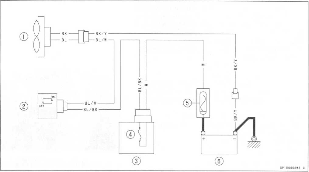
Meter
ELECTRICAL
SYSTEM 16-61
Meter
Assembly Removal
•
Remove:
Upper
Fairing (see Frame chapter)
Meter
Bracket Bolts [A]
Slide
the dust cover [A] and remove the wiring connector.
Remove
the meter unit by taking off the mounting screws
[B]
with the washers.
Place
the meter unit so that the face is up. If a meter
unit
is left upside down or sideways for any length
of
time, it will malfunction. *
•
Meter
Assembly Disassembly •
Remove:
Meter
Assembly (see Meter Assembly Removal) Screws [A]
Lower
Meter Cover [B]
•
Separate
the meter liquid crystal display assembly [A] and upper meter cover
[B],

Caution


http://moto.amoti.rtt/
16-62
ELECTRICAL SYSTEM
Meter,
Gauge, Indicator Unit
Electronic
Combination Meter Assembly Inspection
•
Remove the meter assembly [A],
Ignition
Fuel
Reserve Switch
Stop
Watch (+)
Lap
Time (+)
Neutral
Indicator Light (LED) Ground (-)
FI
Indicator Light (LED) Ground (-)
Tachometer
Pulse
Water
Temperature Sensor
Ground
(-)
Battery
(+)
Oil
Pressure Warning
Indicator
Light (LED)
Ground
(-)
Speed
Sensor Supply
Voltage
Right
Turn Signal Light
(LED)
(+)
Left
Turn Signal Indicator
Light
(LED) (+)
High
Beam Indicator Light
(LED)
Speed
Sensor Pulse
CAUTION
Do
not drop the meter unit. Place the meter unit so that it faces
upward. If the meter assembly is left upside down or sideways
for a long time or dropped, it will malfunction.
CAUTION
Do
not short each terminals.
Liquid
Crystal Display (LCD) Segments Check:
•
Connect
the harness adapter to the meter assembly connector.
Special Tool - Harness Adapter: 57001-1542
• Using the auxiliary wires, connect the 12 V battery to the each connector of harness adapter as follows.
O Connect the battery positive terminal to the terminal [10]. O Connect the battery negative terminal to the terminal [9]. •
• Connect the terminal [1] to the terminal [10].

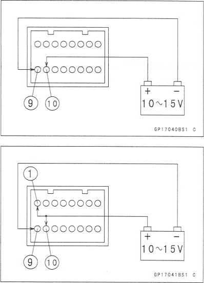
http://moto.amoti.rtt/
Meter,
Gauge, Indicator Unit
ELECTRICAL
SYSTEM 16-63
oThe
tachometer LCD segments momentarily to it last readings two times
and segment movement is reversal.
O
When the terminals are connected, all the LCD segments [A] and LED
warning light [B] appear for three seconds.
If
the LCD segments and LED warning light will not appear,
replace the meter assembly.
Disconnect
the terminal [1],
O
All the LCD segments and LED warning light disappear.
If
the segments do not disappear, replace the meter assembly.
MODE
AND RESET BUTTON Operation Check:
Connect
the 12 V battery and terminals in the same manner as specified
in the "Liquid Crystal Display (LCD) Segments Check".
Check
that the display [B] change to the ODO, TRIP, and CLOCK and STOP
WATCH displays each time the mode selector button [A] is pressed.
If
the display function does not work, replace the meter assembly.
CLOCK
TRIP
ODO
n
/ u
t
/
35.3
BISS
.
<L
uuuuuu
SP17071BS1
C
• Indicate
the clock mode.

Check that when the RESET button in CLOCK mode is pushed for more than two seconds, the meter display turns to the clock set mode.
oBoth the hour and minute display start flashing.

http://moto.amoti.rtt/
• In the HOUR/MINUTE setting mode, press the reset but- |
|
ton [C] again to effect the HOUR setting mode. |
CLOCK \ 1 * |
OThe hour display flashes on the display. |
/ > i? 3 |
• Press the mode selector button [A] to set the hour. |
• i * il |
|
V CLOCK \ •t |
|
1333 # . \ |
• In the HOUR setting mode, press the reset button [C] to |
GP1 7 0 8 2 8 S1 C CLOCK % ■/ |
effect the MINUTE setting mode. |
$ D-D D |
oThe minute display flashes on the display. |
iced |
• Press the mode selector button [A] to set the minute. |
* ■' il |
|
V CLOCK \ ■/ |
|
133 V # ■ \ |
|
QP17C63BS: C |
In
the MINUTE setting mode, press the reset button [C]
to
return to the HOUR/MINUTE setting mode.
Press
the mode selector button [A] to complete the time
setting
process.
oThe
clock starts counting the seconds a soon as the mode
selector
button is pressed. |
% ■ * |
|
133 V * i * p |
CLOCK |
i 133 V |
|
GP17064BS1 C |
Indicate
the ODO mode.
If
the display function does not work and adjust, replace
the
meter assembly.
Check
that the display [A] [B] change to the mile and °F,
Mile
and °C, km and CF,
km and CC
display each time by
pushing
the RESET bottom while MODE bottom pushed
in.
NOTE
O
Mile/Km
Display can alternate between English and
metric
modes (mile and km) in the digital meter. Make
sure
that km or mile according to local regulations is
correctly
displayed before riding.
http://moto.amoti.rtt/
Meter,
Gauge, Indicator Unit
ELECTRICAL
SYSTEM 16-65
Speedometer
Check:
Connect
the 12 V battery and terminals in the same man-
ner
as specified in the "Liquid Crystal Display (LCD) Seg-
ments
Check”.
The
speed equivalent to the input frequency is indicated in
the
oscillator [A], if the square wave (illustrated as shown)
would
be input into the terminal [16],
O
Indicates approximately 60 mph in case the input fre-
quency
would be approximately 146 Hz.
O
Indicates approximately 60 km/h in case the input fre-
quency
would be approximately 91 Hz.
If
the oscillator is not available, the speedometer can be checked as
follows.
o
Install the meter unit.
o
Raise the rear wheel off the ground, using the jack.
oTurn
on the ignition switch.
O
Rotate the rear wheel by hand.
O
Check that the speedometer shows the speed.
If
the speedometer does not work, check the speed sensor electric
source voltage and speed sensor.
★The
electric source voltage and speed sensor are normal, replace the
meter assembly.

Speed Sensor Electric Source Check:
Connect the 12 V battery and terminals in the same man- ner as specified in the "Liquid Crystal Display (LCD) Seg- ments Check".
Set the hand tester to the DC25 V range and connect it to the terminals [12] and [9],
If the voltage is less than 8 V, replace the meter assembly.
Odometer Check:
Check the odometer with the speedometer check in the same way.
If value indicated in the odometer is not added, replace the meter assembly.
NOTE
O The data is maintained even if the battery is discon- nected.
O When the figures come to 999999, they are stopped and locked.

http://moto.amoti.rtt/
TRIP |
^5J |
|
Jl7/ |
|
V n n |
|
u.u API7O708S |
Water
Temperature Meter Check:
Connect
the 12 V battery and terminals in the same man-
ner
as specified in the "Liquid Crystal Display (LCD)
Seg-
ments
Check".
Connect
the variable rheostat [A] to the terminal [8] as
shown.
Check
that the number of segments matches the resis-
tance
value of the variable rheostat. |
Temperature Meter |
Warning Indicate |
|
- |
[A] - |
209.8 |
50°C (122°F) |
[B] - |
69.1 |
80°C (176°F) |
[B] - |
21.2 |
120°C (248"F) |
[C] Flash |
17 |
HI |
[D] Flash |
•
If
any display function does not work, replace the meter assembly.
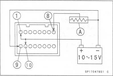

GP1 7077812 C
http://moto.amoti.rtt/
ELECTRICAL SYSTEM 16-67
Meter, Gauge, Indicator Unit
Tachometer Check:
Connect the 12 V battery and terminals in the same manner as specified in the "Liquid Crystal Display (LCD) Segments Check".
The revolutions per minute (rpm) equivalent to the input frequency is indicated in the oscillator [A] if the square wave (illustrated as shown) would be input into the terminal [7],
O Indicates approximately 6500 rpm in case the input frequency would be approximately 200 Hz.

• If the oscillator is not available, the tachometer can be checked as follows.
O Connect the 12 V battery and terminals in the same manner as specified in the "Liquid Crystal Display (LCD) Segments Check".
O Using an auxiliary wire, quickly open and connect the terminal [1] to the terminal [7] repeatedly.
oThen the tachometer segment [A] should flick [B],
★ If the hand does not flick, replace the meter assembly.

Stop Watch Check:
Connect the 12V battery and terminal in the same manner as specified in the “Liquid Crystal Display (LCD) Segments Check”.
Press the mode selector button each time to set the stop watch mode.
Connect the auxiliary wire to the terminal [3] as shown, then stop watch start to count.
While count the stop watch, connect the auxiliary wire to the terminal [4] as shown, then indicate the counted time during ten seconds.

http://moto.amoti.rtt/
16-68
ELECTRICAL SYSTEM
Meter,
Gauge, Indicator Unit
Connect
the variable rheostat [A] to the terminal [8] as shown.
When
Set the resistance to less than 21.1fi, lap display segment
indicate the water temperature.
If
the display function does not work, replace the mater assembly.
LED
Lights Inspection:
•
Connect
the 12 V battery and terminals in the same manner as specified
in the “Liquid Crystal Display (LCD) Segments check.”
Neutral Indicator Light (LED) [A]
FI Indicator Light (LED) [B]
Oil Pressure Warning Indicator Light (LED) [C]
Turn Signal Indicator Light (LED) [D]
High Beam Indicator Light (LED) [E]
Fuel Level Warning Indicator Light (LED) [F]
Shift Up Indicator Light (LED) [G]

GP17081BS1 C

• Using the auxiliary leads and harness adapter, connect a 12 V battery to the meter unit connector as follows.
Special Tool - Harness Adapter: 57001-1542 Neutral Indicator Light (LED):Battery Negative (-) Terminal To Terminal [5]
FI Indicator Light (LED):
Battery Negative (-) Terminal To Terminal [6]

http://moto.amoti.rtt/
Meter,
Gauge, Indicator Unit
ELECTRICAL
SYSTEM 16-69
Oil
Pressure Warning Indicator Light (LED):
Battery
Negative (-) Terminal To Terminal [11]
Right
and Left Turn Signal Indicator Light (LED):
Battery
Positive (+) Terminal to Terminal [13] Battery Positive (+) Terminal
to Terminal [14]
High
Beam Indicator Light (LED):
Battery
Positive (+) Terminal to Terminal [15]
Fuel
Level Warning Indicator Light (LED):
Connect
a variable rheostat [C] to terminal [2] and [9] as shown.
Adjust
the resistance value to the approximately 22 fi.
http://mofo.amofi.rtt/


II |
|
ft |
^ A @ |
GP17033BW2
C
Turn
Signal Indicator Light (LED)
High
Beam Indicator Light (LED)
Neutral
Indicator Light (LED)
Oil
Pressure Warning Indicator Light (LED)
Fuel
Level Warning Indicator Light (LED)
FI
Indicator Light (LED)
Odometer/Trip
Meter/ Clock/Stop Watch Indicator
Water
Temperature Gauge
Tachometer
Speedometer
Meter
Light (LED)
Shift
Up Indicator Light (LED)
Meter
Assembly
Frame
Ground
Stop
Watch Switch
Speed
Sensor
Fuel
Reserve Switch
Water
Temperature Sensor
Oil
Pressure Switch
Neutral
Switch
Ignition
Switch
Lap
Switch
Junction
Box
ACC
Fuse 10A
Ignition
Fuse 10A
Main
Fuse 30A
Battery
12 V 8 Ah
E.C.U.
http://moto.amoti.ru/
Switches
and Sensors
ELECTRICAL
SYSTEM 16-71
Brake
Light Timing Inspection
o
Refer to the Brakes in the Periodic Maintenance chapter.
Brake
Light Timing Adjustment
o
Refer to the Brakes in the Periodic Maintenance chapter.
Switch
Inspection
Using
a hand tester, check to see that only the connections shown in
the table have continuity (about zero ohms).
oFor
the handlebar switches and the ignition switch, refer to the tables
in the Wiring Diagram.
If
the switch has an open or short, repair it or replace it
with
a new one.
Special
Tool - Hand Tester: 57001-1394 Rear Brake Light Switch Connections
*:
Engine lubrication system is in good condition
http://moto.amoti.rtt/

16-72
ELECTRICAL SYSTEM
Switches
and Sensors
Radiator
Fan Switch Inspection
Remove
the fan switch (see Cooling System chapter).
Suspend
the switch [A] in a container of coolant so that the
temperature-sensing projection and threaded portion are submerged.
Suspend
an accurate thermometer [B] in the coolant.
NOTE
O
The
switch and thermometer must not touch the container sides or
bottom.
Place
the container over a source of heat and gradually raise the
temperature of the coolant while stirring the coolant gently.
Using
the hand tester, measure the internal resistance of the switch
across the terminals at the temperatures shown in the table.
If
the hand tester does not show the specified values, replace
the switch.
Fan
Switch Resistance Rising temperature:
From
OFF to ON at 93 - 103°C (199 ~ 217°F)
Falling
temperature:
Fan
stops with the temperature 3 ~ 8°C (38 ~ 46°F) lower than the
operation temperature range.
ON:
Less than 0.5 f2
OFF:
More than 10 Mt2
http://moto.amoti.rtt/

Resistance for ECU [C] |
|
Temperature |
Resistance (kfi) (Terminal [1] - [3]) |
20°C (68° F) |
„ _ + 0.115 2.46 -0.143 |
80°C (176°F) |
0.32 ± 0.011 |
110°C (230°F) |
0.1426 ± 0.0041 |
Resistance for Water Temperature Gauge [D] |
|
Temperature |
Resistance (fl) (Terminal [2] - Body) |
50°C (122°F) |
210 ± 40 |
120°C (248CF) |
21.2 ± 1.5 |
Speed
Sensor Removal •
Remove:
Fuel
Tank (see Fuel system (DFI) chapter) Reserve Tank [A]
Speed
Sensor Bolt [B]
http://moto.amoti.rtt/
16-74
ELECTRICAL SYSTEM
Switches
and Sensors
Disconnect
the speed sensor lead connector [A],
Remove
the speed sensor.
Speed
Sensor Installation •
Install the speed sensor.
Torque
- Speed Sensor Bolt: 3.9 N m (0.40 kgf-m, 35 in-lb)
Speed
Sensor Inspection
Remove:
Speed
Sensor (see Final Drive chapter)
Connect
the speed sensor connector [A] with the battery [B], 10 k$]
resistor [C] and hand tester [D] as shown.
Set
the tester to the DC 25 V range.
Special
Tool - Hand Tester: 57001-1394
Trace
[A] each side of the speed sensor surface with the screw driver.
oThen
the tester indicator should flick [B],
If
the tester indicator does not flick, replace the speed sensor.
Fuel
Reserve Switch Inspection (1)
Fill
the fuel tank with fuel.
Close
the fuel tank cap surely.
Remove
the fuel tank (see Fuel System (DFI) chapter).
Connect
the test light [A] (12 V 3.4 W bulb a socket with leads) and the 12
V battery [B] to the fuel pump connector [C].
Connections:
Battery
(+) -> 12 V 3.4 W Bulb (one side)
12
V 3.4 W Bulb (other side) -> R/BK Lead Terminal Battery (-) ->
BK/W Lead Terminal
Special
Tool - Needle Adapter Set: 57001-1457
★
If
the test light turn on, the reverse switch is defective. Replace the
fuel pump.


®
0C25V 0P180701S1 C
http://moto.amoti.rtt/
Switches
and Sensors
ELECTRICAL
SYSTEM 16-75
Fuel
Reserve Switch Inspection (2)
Remove:
Fuel
Pump (see Fuel System (DFI) chapter)
Connect
the test light (12 V 3.4 W bulb in a socket with leads) and the 12
V battery to the fuel pump connector as shown.
12
V Battery [A]
Test
Light [B]
Fuel
Pump Connector [C]
Fuel
Reserve Switch [D]
If
the test light doesn’t light, replace the fuel pump.
NOTE
O
It
may take a long time to turn on the test light in case that the fuel
reserve switch is inspected just after the fuel pump is removed.
Leave the fuel reserve switch with leads for inspection connected
for one (1) minute.
http://moto.amoti.rtt/

Tester Connection |
Tester Reading (fi) |
Tester Connection |
Tester Reading (fi) |
1 - 1A |
0 |
1A - 8 |
X |
1 - 2 |
0 |
2 - 8 |
X |
3A - 4 |
0 |
3A - 8 |
X |
6 - 5 |
0 |
6 - 2 |
X |
6 - 10 |
0 |
6 - 3A |
X |
6 - 7 |
0 |
17 - 3A |
X |
6 - 17 |
0 |
|
|
Starter
Circuit/Headlight Relay Inspection
Remove
the junction box.
Check
conductivity of the following numbered terminals by connecting the
hand tester and one 12 V battery to the junction box as shown.
If
the tester does not read as specified, replace the junction
box.
Special
Tool - Hand Tester: 57001-1394
http://moto.amoti.rtt/
|
Tester Connection |
Tester Reading m |
|
Tester Connection |
Tester Reading (fi) |
Headlight Relay |
7 - 8 |
X |
Starter Circuit Relay |
9 - 11 |
X |
7 - 13 |
X |
12 - 13 |
X |
||
(+) (-) 13 - 9 |
Not x * |
(+) (-) 13-11 |
X |
||
(+) (-) 12 - 11 |
Not X * |
(*):
The actual reading varies with the hand tester used. (+): Apply
tester positive lead.
(-):
Apply tester negative lead.
Relay
Circuit Inspection (with the battery connected) |
Battery Connection (+) H |
Tester Connection |
Tester Reading (fl) |
Headlight Relay |
9-13 |
7-8 |
0 |
Starter Circuit Relay |
11 - 12 |
(+) H 13 - 11 |
Not x * |
(*):
The actual reading varies with the hand tester used (+): Apply
tester positive lead.
(-):
Apply tester negative lead.
Diode
Circuit Inspection
Remove
the junction box.
Check
conductivity of the following pairs of terminals.
Diode
Circuit Inspection
Tester
Connection
13-8,
13-9, 12-11, 12-14,
15-14.
16-14
★The
resistance should be low in one direction and more than ten times as
much in the other direction. If any diode shows low or high in both
directions, the diode is defective and the junction box must be
replaced.
NOTE
O The actual meter reading varies with the meter used and the individual diodes, but, generally speaking, the lower reading should be from zero to one half the scale.
http://moto.amoti.rtt/
16-78 ELECTRICAL SYSTEM
Junction Box
Junction Box Internal Circuit

Turn Signal Relay Fuse 10 A
Horn Fuse 10 A
Ignition Fuse 10 A
Headlight Fuse 10 A
Starter Diode
J. Starter Circuit Relay
K. Interlock Diodes
Taillight Fuse 10 A
http://moto.amoti.rtt/
Fuse
ELECTRICAL
SYSTEM 16-79
30
A Main Fuse Removal
Remove:
Seats
(see Frame chapter)
Starter
Relay and 30 A Main Fuse Connector [A]
Pull
out the main fuse [B] from the starter relay with needle nose
pliers.
Junction
Box Fuse Removal
Remove
the seats (see Frame chapter).
Unlock
the hook to lift up the lid [A],
Pull
the fuses [B] straight out of the junction box with needle
nose pliers.
15A
ECU Fuse Removal
•
Remove:
Seats
(see Frame chapter)
15A
ECU Fuse [A]
Fuse
Installation
If
a fuse fails during operation, inspect the electrical system
to determine the cause, and then replace it with a new fuse of
proper amperage.
Install
the junction box fuses on the original position as specified on the
lid.
http://moto.amoti.rtt/

16-80
ELECTRICAL SYSTEM
Fuse
Fuse
Inspection
Remove
the fuse (see Fuse Removal).
Inspect
the fuse element.
If
it is blown out, replace the fuse. Before replacing a
blown
fuse, always check the amperage in the affected
circuit.
If the amperage is equal to or greater than the
fuse
rating, check the wiring and related components for
a
short circuit.
Housing
[A] Terminals [C]
Fuse
Element [B] Blown Element [D]
CAUTION
When
replacing a fuse, be sure the new fuse matches the specified fuse
rating for that circuit. Installation of a fuse with a higher rating
may cause damage to wiring and components.
http://moto.amoti.ru/

APPENDIX
17-1
Cable,
Wire, and Hose Routing 17_2
Troubleshooting
Guide 17-12
17
http://moto.amoti.rtt/Appendix table of contents
17-2
APPENDIX
Cable,
Wire, and Hose Routing
Clucth
Cable
Choke
Cable
Throttle
Cables
Coolant
Reserve Tank Hose
Coolant
By-pass Hose
Main
Harness
Turn
Signal Light Lead
Left
Handlebar Switch Lead
Right
Handlebar Switch Lead
Run
the starter cable under the throttle cables and clutch cable.
Run
the clutch cable and through the clamp.
Clamp
the throttle cables and clutch cable and run the clutch cable above
the throttle cables.
Run
the clutch cable above the coolant hose and through the main
harness inside.
Run
the meter lead forward the bracket.
Clamp
the meter lead.
Run
the left handlebar switch lead under the main harness.
Clamp
the left handlebar switch lead.
Clamp
the headlight lead and the left handlebar switch lead.
http://moto.amoti.rtt/
APPENDIX
17-3
Seat
Lock Cable
ECU
(Electrical Control Unit)
ECU
Fusel 5A
Turn
Signal Relay
Fuel
Pump Relay
ECU
Main Relay
Battery
(+) Lead
Battery
Vehicle-down
Sensor
Frame
Ground
Clamp
Self-diagnosis
Terminal
Battery
(-) Lead
Junction
Box
Clamp
Starter
Relay and Main Fuse30A
Turn
Signal Light Lead Connector(Left and Right), License Light Lead
Connector and Tail/Brake Light(LED) Lead Connector
Clamp
http://moto.amoti.rtt/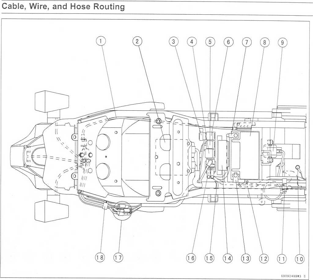
17-4
APPENDIX
Cable,
Wire, and Hose Routing
To
Speed Sensor
Regulator/Rectifire
Lead
To
Regulator/Rectifire
To
Starter Motor
Clamp
the ignition switch lead and horn lead.
Run
the ignition switch lead above the choke cable and throttle cables.
Horn
Lead
To
Meter Assembly
To
Turn Signal Lead
To
Headlight
To
Left Handlebar Switch
Right
Handlebar Switch Lead
Clamp
the horn lead, ignition switch lead and right handlebar switch
lead.
To
Ignition Switch
Clamp
Inlet
Air Temperature Switch
To
Injector
To
Fuel Pump
Clamp
Place
the brake switch connector forward than rear brake reservoir
bracket.
Rear
Brake Switch Lead
Clamp
the main harness, rear brake switch, battery(-)lead and starter
motor lead.
http://moto.amoti.rtt/
APPENDIX
17-5
Cable,
Wire, and Hose Routing
To
Air Radiator Fan Switch
Vacuum
Switch Valve
Tighten
with the ground lead and clamp.
Run
the subthrottle lead under the vacuum switch hose.
Insert
the connectors to the plate.
From
the Throttle Body Assembly
Face
the white mark upward.
To
Radiator Fan.
Insert
the connector to the plate.
To
Oil Pressure Switch
Main
Harness
Clamp
Regulator/Rectifire
Lead
Starter
Motor Lead
Battery
(-) Lead
To
Speed Sensor
To
Side Stand Switch
To
Neutral Switch
To
Alternator
Clamp
Starter
Motor Lead
Run
the speed sensor lead inside the engine sprocket cover hook.
Clamp
the side stand switch lead.
Neutral
Switch
http://moto.amoti.rtt/
17-6
APPENDIX
Cable,
Wire, and Hose Routing
Through
the clamp to the rubber cover hole, and bend it for hold the rubber
cover.
Radiator
Fan Lead
Clamp
the radiator fan switch lead.
Camshaft
Position lead
Through
the horn lead outside the bracket of radiator upside, and through
it between frame and radiator.
Clamp
the ignition switch lead and horn lead.
http://moto.amoti.rtt/
APPENDIX
17-7
Cable,
Wire, and Hose Routing
Reserve
Tank Overflow Hose
Fuel
Tank Drain Hose
Air
Cleaner Housing Drain Hose
Clamp
the air cleaner housing drain hose.
Clamp
the reserve tank overflow hose and fuel tank drain hose.
http://moto.amoti.rtt/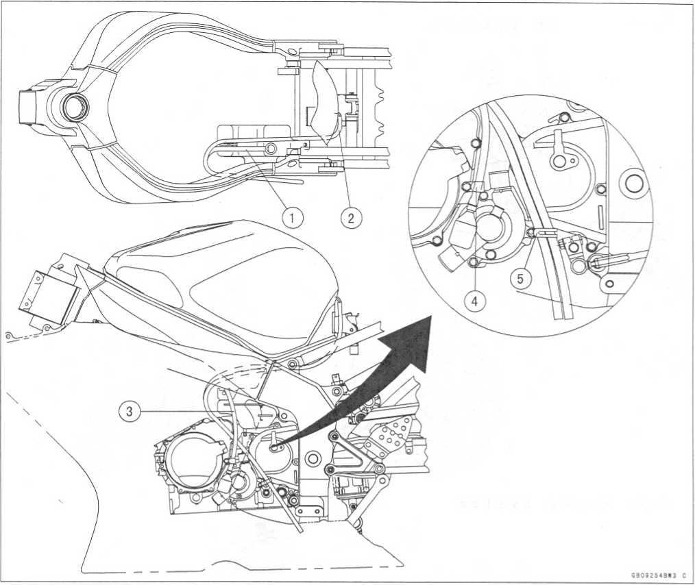
17-8
APPENDIX
Cable,
Wire, and Hose Routing
Front
Master Cylinder
Front
Brake Reservoir Tank
Clamp
(Installed to the front fender)
Front
Brake Caliper
Clamp
Rear
Brake Master Cylinder
Rear
Brake Reservoir Tank
Rear
Brake Caliper
The
brake hose shall be installed so that the white mark on it faces to
outside.
http://moto.amoti.rtt/
APPENDIX
17-9
Cable,
Wire, and Hose Routing
Radiator
Reserve
Tank Hose
Coolant
By-pass Hose
Face
the clamp screw rear and approximately 30 inside.
Face
the clamp screw downward.
Face
the white mark forward.
To
Cylinder Head Fitting
Align
the mark.
To
Reserve Tank
Run
the reserve tank hose under the starter motor lead.
Run
the reserve tank hose under the speed sensor lead.
http://moto.amoti.ru/
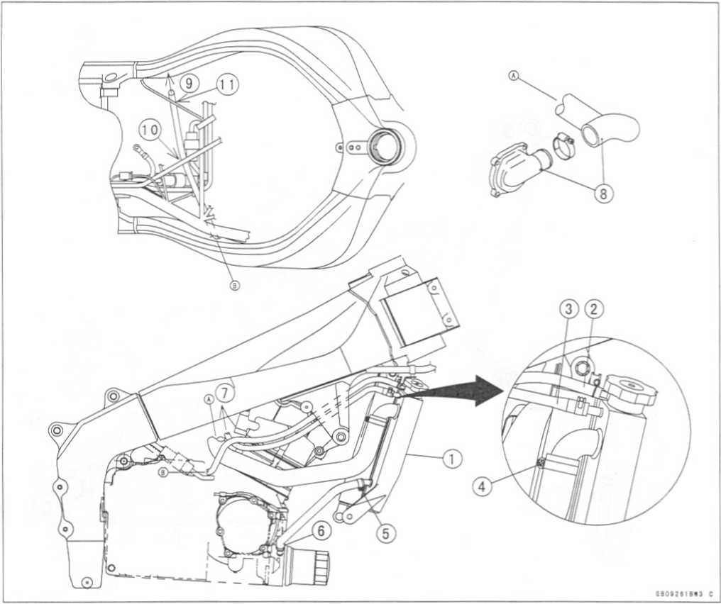
17-10
APPENDIX
Cable,
Wire, and Hose Routing
To
Radiator
Face
the clamp screw downward.
Cylinder
Fitting.
Water
Pump.
Align
the mark.
http://moto.amoti.rtt/
APPENDIX
17-11
Cable,
Wire, and Hose Routing
California
Evaporative Emission Control System
Band
Face
the hole downward.
Separator
Fitting
Face
the claw outside.
To
Separator (Blue)
To
Fuel Tank (Red)
To
Canister (Blue)
To
Throttle Body #4 (white)
To
Vacuum Switch(Green)
http://mofo.amoti.ru/
17-12
APPENDIX
Troubleshooting
Guide
NOTE
O
Refer
to the Fuel System chapter for most of DFI trouble shooting guide.
O
This
is not an exhaustive list, giving every possible cause for each
problem listed. It is meant simply as a rough guide to assist the
troubleshooting for some of the more common difficulties.
Engine
Doesn’t Start, Starting Difficulty:
Starter
motor not rotating:
Starter
lockout switch or neutral switch trouble
Starter
motor trouble Battery voltage low
Starter
relay not contacting or operating
Starter
button not contacting
Wiring
open or shorted
Ignition
switch trouble
Engine
stop switch trouble
Fuse
blown
Starter
motor rotating but engine doesn’t turn over:
Starter
clutch trouble Vehicle-down sensor (DFI) coming off Engine
won’t turn over:
Valve
seizure Valve lifter seizure Cylinder, piston seizure Crankshaft
seizure Connecting rod small end seizure Connecting rod big end
seizure Transmission gear or bearing seizure Camshaft seizure
Starter idle gear seizure No
fuel flow:
No
fuel in tank Fuel pump trouble Fuel tank air vent obstructed Fuel
filter clogged Fuel line clogged Engine
flooded:
Clean
spark plug and adjust plug gap Starting technique faulty (When
flooded, do not crank the engine with the throttle fully opened.
This promotes engine flood because more fuel is supplied
automatically by DFI.)
No
spark; spark weak:
Vehicle-down
sensor (DFI) coming off Ignition switch not ON Engine stop switch
turned OFF
Clutch
lever not pulled in or gear not in neutral
Battery
voltage low
Spark
plug dirty, broken, or gap maladjusted
Stick
coil shorted or not in good contact Stick coil trouble Spark plug
incorrect IC igniter in ECU trouble Camshaft position sensor trouble
Neutral, starter lockout, or side stand switch trouble
Crankshaft
sensor trouble Ignition switch or engine stop switch shorted
Wiring
shorted or open Fuse blown
Fuel/air
mixture incorrect:
Bypass
screw and/or idle adjusting screw maladjusted Air passage clogged
Air
cleaner clogged, poorly sealed, or missing
Compression
Low:
Spark
plug loose
Cylinder
head not sufficiently tightened down
No
valve clearance Cylinder, piston worn
Piston
ring bad (worn, weak, broken, or sticking)
Piston
ring/groove clearance excessive Cylinder head gasket damaged
Cylinder head warped Valve spring broken or weak Valve not seating
properly (valve bent, worn, or carbon accumulation on the seating
surface)
Poor
Running at Low Speed:
Spark
weak:
Battery
voltage low
Spark
plug dirty, broken, or maladjusted Stick coil wiring trouble Stick
coil not in good contact Spark plug incorrect IC igniter in ECU
trouble Camshaft position sensor trouble Crankshaft sensor trouble
Stick coil trouble Fuel/air
mixture incorrect:
Bypass
screw maladjusted Air passage clogged
http://moto.amoti.ru/
Troubleshooting
Guide
APPENDIX
17-13
Air
bleed pipe bleed holes clogged Pilot passage clogged Air cleaner
clogged, poorly sealed, or missing
Fuel
tank air vent obstracted Fuel pump trouble Throttle body assy holder
loose Air cleaner duct loose Compression
low:
Spark
plug loose
Cylinder
head not sufficiently tightened down
No
valve clearance Cylinder, piston worn
Piston
ring bad (worn, weak, broken, or sticking)
Piston
ring/groove clearance excessive Cylinder head warped Cylinder head
gasket damaged Valve spring broken or weak Valve not seating
properly (valve bent, worn, or carbon accumulation on the seating
surface)
Other:
IC
igniter in ECU trouble
Throttle
body assy not synchronizing
Engine
oil viscosity too high
Drive
train trouble
Brake
dragging
Air
suction valve trouble
Vacuum
switch valve trouble
Engine
overheating
Clutch
slipping
Poor
Running or No Power at High Speed:
Firing
incorrect:
Spark
plug dirty, broken, or maladjusted Stick coil wiring trouble Stick
coil not in good contact Spark plug incorrect Camshaft postion
trouble IC igniter in ECU trouble Crankshaft sensor trouble Stick
coil trouble Fuel/air
mixture incorrect:
Air
cleaner clogged, poorly sealed, or missing
Air
cleaner O-ring damaged Air cleaner duct loose
Water
or foreign matter in fuel Throttle body assy holder loose Fuel to
injector insufficient (DFI)
Fuel
tank air vent obstructed
Fuel
line clogged
Fuel
pump trouble (DFI)
Compression
low:
Spark
plug loose
Cylinder
head not sufficiently tightened down
No
valve clearance Cylinder, piston worn
Piston
ring bad (worn, weak, broken, or sticking)
Piston
ring/groove clearance excessive Cylinder head gasket damaged
Cylinder head warped Valve spring broken or weak Valve not seating
properly (valve bent, worn, or carbon accumulation on the seating
surface.)
Knocking:
Carbon
built up in combustion chamber Fuel poor quality or incorrect Spark
plug incorrect IC igniter in ECU trouble Camshaft position sensor
trouble Crankshaft sensor trouble Miscellaneous:
Throttle
valve won't fully open Brake dragging Clutch slipping Engine
overheating Engine oil level too high Engine oil viscosity too high
Drive train trouble Air suction valve trouble Vacuum switch valve
trouble Catalytic converter melt down due to muffler overheating
(KLEEN)
Overheating:
Firing
incorrect:
Spark
plug dirty, broken, or maladjusted Spark plug incorrect IC igniter
in ECU trouble
http://moto.amoti.rtt/
17-14
APPENDIX
Troubleshooting
Guide
Muffler
overheating:
For
KLEEN, do not run the engine even if with only one cylinder
misfiring or poor running (Request the nearest service facility
to correct it)
For
KLEEN, do not push-start with a dead battery (Connect another
full-charged battery with jumper cables, and start the engine using
the electric starter)
For
KLEEN, do not start the engine under misfire due to spark plug
fouling or poor connection of the stick coil For KLEEN, do not coast
the motorcycle with the ignition switch off (Turn the ignition
switch ON and run the engine)
Throttle
body assy holder loose Air cleaner duct loose Air cleaner poorly
sealed, or missing Air cleaner O-ring damaged Air cleaner clogged
Compression
high:
Carbon
built up in combustion chamber Engine
load faulty:
Clutch
slipping Engine oil level too high Engine oil viscosity too high
Drive train trouble Brake dragging Lubrication
inadequate:
Engine
oil level too low Engine oil poor quality or incorrect Oil
cooler incorrect:
Oil
cooler clogged Gauge
incorrect:
Water
temperature gauge broken Water temperature sensor broken Coolant
incorrect:
Coolant
level too low Coolant deteriorated Wrong coolant mixed ratio Cooling
system component incorrect: Radiator
fin damaged Radiator clogged Thermostat trouble Radiator cap trouble
Radiator fan switch trouble Radiator fan relay trouble Fan motor
broken Fan blade damaged Water pump not turning Water pump impeller
damaged
Over
Cooling:
Gauge
incorrect:
Water
temperature gauge broken Water temperature sensor broken Cooling
system component incorrect:
Radiator
fan switch trouble Thermostat trouble
Clutch
Operation Faulty:
Clutch
slipping:
Friction
plate worn or warped Steel plate worn or warped Clutch spring broken
or weak Clutch hub or housing unevenly worn No clutch lever play
Clutch inner cable trouble Clutch release mechanism trouble Clutch
not disengaging properly:
Clutch
plate warped or too rough Clutch spring compression uneven Engine
oil deteriorated Engine oil viscosity too high Engine oil level too
high Clutch housing frozen on drive shaft Clutch hub nut loose
Clutch hub spline damaged Clutch friction plate installed wrong
Clutch lever play excessive Clutch release mechanism trouble
Gear
Shifting Faulty:
Doesn’t
go into gear; shift pedal doesn’t return:
Clutch
not disengaging Shift fork bent or seized Gear stuck on the shaft
Gear positioning lever binding Shift return spring weak or broken
Shift return spring pin loose Shift mechanism arm spring broken
Shift mechanism arm broken Shift pawl broken Jumps
out of gear:
Shift
fork ear worn, bent Gear groove worn Gear dogs and/or dog holes worn
Shift drum groove worn Gear positioning lever spring weak or broken
Shift
fork guide pin worn Drive shaft, output shaft, and/or gear splines
worn
http://moto.amoti.ru/Ic igniter in ecu trouble Fuel/air mixture incorrect:
Troubleshooting
Guide
APPENDIX
17-15
Overshifts:
Gear
positioning lever spring weak or broken
Shift
mechanism arm spring broken
Abnormal
Engine Noise:
Knocking:
IC
igniter in ECU trouble Carbon built up in combustion chamber Fuel
poor quality or incorrect Spark plug incorrect Overheating Piston
slap:
Cylinder/piston
clearance excessive Cylinder, piston worn Connecting rod bent Piston
pin, piston pin hole worn Valve
noise:
Valve
clearance incorrect Valve spring broken or weak Camshaft bearing
worn Valve lifter worn Other
noise:
Connecting
rod small end clearance excessive •
Connecting
rod big end clearance excessive
Piston
ring/groove clearance excessive Piston ring worn, broken, or stuck
Piston ring groove worn Piston seizure, damage Cylinder head gasket
leaking Exhaust pipe leaking at cylinder head connection
Crankshaft
runout excessive Engine mount loose Crankshaft bearing worn Primary
gear worn or chipped Camshaft chain tensioner trouble Camshaft
chain, sprocket, guide worn Air suction valve damaged Vacuum switch
valve damaged Alternator rotor loose
Catalytic
converter melt down due to muffler overheating (KLEEN)
Abnormal
Drive Train Noise:
Clutch
noise:
Clutch
damper weak or damaged Clutch housing/friction plate clearance
excessive
Clutch
housing gear worn
Wrong
installation of outside friction plate
Transmission
noise:
Bearings
worn
Transmission
gear worn or chipped Metal chips jammed in gear teeth Engine oil
insufficient Drive
line noise:
Drive
chain adjusted improperly Drive chain worn
Rear
and/or engine sprocket worn Chain lubrication insufficient Rear
wheel misaligned
Abnormal
Frame Noise:
Front
fork noise:
Oil
insufficient or too thin Spring weak or broken Rear
shock absorber noise:
Shock
absorber damaged Disc
brake noise:
Pad
installed incorrectly Pad surface glazed Disc warped Caliper trouble
Other
noise:
Bracket,
nut, bolt, etc. not properly mounted or tightened
Oil
Pressure Warning Light Goes On:
Engine
oil pump damaged Engine oil screen clogged Engine oil filter clogged
Engine oil level too low Engine oil viscosity too low Camshaft
bearing worn Crankshaft bearing worn Oil pressure switch damaged
Wiring faulty Relief valve stuck open O-ring at the oil passage in
the crankcase damaged
Exhaust
Smokes Excessively:
White
smoke:
Piston
oil ring worn Cylinder worn Valve oil seal damaged Valve guide worn
Engine oil level too high Black
smoke:
Air
cleaner clogged Brown
smoke:
Air
cleaner duct loose Air cleaner O-ring damaged
http://moto.amoti.ru/
17-16
APPENDIX
Troubleshooting
Guide
Air
cleaner poorly sealed or missing
Handling
and/or Stability Unsatisfactory:
Handlebar
hard to turn:
Cable
routing incorrect Hose routing incorrect Wiring routing incorrect
Steering stem nut too tight Steering stem bearing damaged Steering
stem bearing lubrication inadequate
Steering
stem bent Tire air pressure too low Handlebar
shakes or excessively vibrates:
Tire
worn
Swingarm
pivot bearing worn Rim warped, or not balanced Wheel bearing worn
Handlebar clamp bolt loose Steering stem nut loose Front, rear axle
runout excessive Engine mounting bolt loose Handlebar
pulls to one side:
Frame
bent
Wheel
misalignment
Swingarm
bent or twisted
Swingarm
pivot shaft runout excessive
Steering
maladjusted
Front
fork bent
Right
and left front fork oil level uneven Shock
absorption unsatisfactory:
(Too
hard)
Front
fork oil excessive
Front
fork oil viscosity too high
Rear
shock absorber adjustment too hard
Tire
air pressure too high
Front
fork bent
(Too
soft)
Tire
air pressure too low
Front
fork oil insufficient and/or leaking
Front
fork oil viscosity too low
Rear
shock adjustment too soft
Front
fork, rear shock absorber spring weak
Rear
shock absorber oil leaking
Brake
Doesn’t Hold:
Air
in the brake line Pad or disc worn Brake fluid leakage Disc warped
Contaminated pad Brake fluid deteriorated Primary or secondary cup
damaged in master cylinder
Master
cylinder scratched inside
Battery
Trouble:
Battery
discharged:
Charge
insufficient
Battery
faulty (too low terminal voltage) Battery lead making poor contact
Load excessive (e.g., bulb of excessive wattage)
Ignition
switch trouble Alternator trouble Wiring faulty
Regulator/rectifier
trouble Battery
overcharged:
Alternator
trouble ' Regulator/rectifier trouble Battery faulty
http://moto.amoti.ru/